New I3 build in Wellington
Posted by tim_kberg
|
New I3 build in Wellington December 04, 2014 03:03PM |
Registered: 9 years ago Posts: 26 |
Hi All
Another newbie venturing into the 3D printing world. I am planning on building a box-frame I3 as it seems one of the simplest ones available. Been shadowing the forums for the last few months and gleaning what I can. Particularly Zerker and his build log
At the moment I am creating a spreadsheet for parts based on this BOM: www.kitbom.com. I will post it up once it is complete along with the suppliers I end up using for others to reference. Undecided whether to go with the Raldrich extruder listed on the BOM or the "standard" Wade's extruder (or if they are the same and I am missing something)
Happy to take any suggestions you folks have for recommended suppliers- particularly looking for recommendations on a local supply of steel/ fasteners. AliExpress seems to be the way to go, along with mike_p (via trademe/ makershop)
Also looking for someone to help with the printed parts- price to be negotiated
All going well I hope to have the parts by Christmas to put it together in my break. Will keep a semi- build log going here, along with any questions I have along the way- I expect there to be a few!!
Cheers in advance
Tim
Edited 1 time(s). Last edit at 12/04/2014 03:03PM by tim_kberg.
|
Re: New I3 build in Wellington December 04, 2014 10:25PM |
Registered: 9 years ago Posts: 118 |
I think the projected cost on that BOM is wishful thinking,budget for up to $700NZ.
There are several good hardware suppliers in nz,such as EDL,Black,s,etc.
The smooth rods may be hard to get,there are some on trade me,but expensive.
For the threaded rod,I would use stainless,but this is of course more expensive.Many people use zinc plated rod,and are happy enough with that.
Get a J-head hotend directly from hotends.com.Cheaper in the long run,unless you have access to machine shop,and skills how to use it.
You may have to get some other parts from overseas(China),but watch freight costs,they can make it uneconomic.
Bearings are cheap from a local skate shop,or trade me.
You might actually consider buying a kit,it does save a lot of hunting for bits.
I bought a kit from China,but with a Melzi board.That cost about $560NZ,but you might have to pay GST and customs fess,adding up to $120.
I have already spent another $300+ for better electronics,and a few other upgrades,but the basic kit will give you a working printer to start with.
I think one of the posters on here has his own kit for sale on trade me,at what seems a pretty reasonable price.Maybe he will chime in.
If it had been available when ibought mine,i wouldn't have bothered to get the china one.
I have only been at it for 3 months ,so my advice is worth what you paid for it
|
Re: New I3 build in Wellington December 05, 2014 08:06PM |
Registered: 9 years ago Posts: 9 |

|
Re: New I3 build in Wellington December 06, 2014 10:51PM |
Registered: 9 years ago Posts: 118 |
|
Re: New I3 build in Wellington December 09, 2014 10:14PM |
Registered: 9 years ago Posts: 26 |
Looking at Aliexpress, and trying to decide which RAMPS kit/ mega 2560/ steppers to get.
This supplier seems to have a lot of good stuff, with a full set, but its not tested. RAMPS+mega+steppers+heatsink.
This kit (again with everything) is "tested", but no-one has bought many kits from them RAMPS+mega+tested
www.buyincoins.com also has a kit at a very good price (US$45) and I have read good things about their quality, but they are out of stock www.buyincoins.com
Any advice on what to look for/ avoid? Or should I just buy the pieces individually for better assurance.
I see a few kits with the mk2 hotbed and LCD screen included. Again is there anything to look for or avoid? eg www.aliexpress.com- full kit
|
Re: New I3 build in Wellington December 09, 2014 10:53PM |
Registered: 9 years ago Posts: 26 |
Apologies for the repost- the first one didn't appear
//Looking at electronics, and and getting stuck on what may be the best option.
Found a RAMPS+mega+steppers+heat sinks kit at www.buyincoins.com (which I have heard good things about) but that is out of stock
Aliexpress has a full kit from a supplier that is not tested, but the supplier seems to have good rep www.aliexpress.com
Another supplier is "tested", but doesnt have many sales: www.aliexpress.com
There are also a few suppliers with kits that include the mk2 hotbed and LCD screen- are those any good?
Choices choices choices... Any advice?//
Edited 2 time(s). Last edit at 12/10/2014 04:12AM by tim_kberg.
|
Re: New I3 build in Wellington December 10, 2014 01:38AM |
Registered: 9 years ago Posts: 118 |
I bought this lot:
[www.hobbyking.com]
Unfortunately,their shipping is a bit higher than most,but since i usually buy some other stuff at the same time,it evens out.
With Aliexpress,quality is always going to be a crap shoot,but I haven't had any problems with sellers as such.
And let's face it,most of the electronics are made in China anyway,it's just that other suppliers often test their products before selling them.
You pays yer money and takes yer chance.
And with the price the first seller offers,you could get 2 sets for the same price as 1 from the other.And free shipping.
As for the hot bed,mine came in the chinese kit,and has performed faultlessly,so I would have no hesitation in buying one from there again.
On the other hand,if you want it in a hurry,and would like some sort of comeback if it,s faulty,there are several suppliers on trade me around the $30 mark.
I haven't yet tried the LCD screen that came with my ramps set.
Edited 2 time(s). Last edit at 12/10/2014 01:44AM by clogs51.
[www.hobbyking.com]
Unfortunately,their shipping is a bit higher than most,but since i usually buy some other stuff at the same time,it evens out.
With Aliexpress,quality is always going to be a crap shoot,but I haven't had any problems with sellers as such.
And let's face it,most of the electronics are made in China anyway,it's just that other suppliers often test their products before selling them.
You pays yer money and takes yer chance.
And with the price the first seller offers,you could get 2 sets for the same price as 1 from the other
.And free shipping.As for the hot bed,mine came in the chinese kit,and has performed faultlessly,so I would have no hesitation in buying one from there again.
On the other hand,if you want it in a hurry,and would like some sort of comeback if it,s faulty,there are several suppliers on trade me around the $30 mark.
I haven't yet tried the LCD screen that came with my ramps set.
Edited 2 time(s). Last edit at 12/10/2014 01:44AM by clogs51.
|
Re: New I3 build in Wellington - Help wanted December 14, 2014 10:00PM |
Registered: 9 years ago Posts: 26 |
Time to bite the bullet and jump into the deep end. I am planning to order the following from Aliexpress in the next couple of days.
If anyone sees something they think I should avoid/ change, comments are greatly appreciated.
I decided to source most of the parts from one supplier, as they have had a few good reviews on some of the items.
RAMPS 1.4 + Mega 2560 + steppers + heatsinks: www.aliexpress.com
GT2 belt + pulleys: www.aliexpress.com
Linear rods: www.aliexpress.com (Same supplier as Zerker had- here's hoping for the same luck)
NEMA 17 motors: www.aliexpress.com
Hotbed: www.aliexpress.com
L8MUU (with spares) : www.aliexpress.com
Cabling (because why not? ) :www.aliexpress.com
Thermistors: www.aliexpress.com
endstops: www.aliexpress.com
I have sourced a 520W ATX from a colleague, and will shop around for S/S threaded rod, fasteners and glass locally. Will get proper j-head (3mm, 0.4mm nozzle) from hotends.com
Any recommendations where to get a hobbed bolt from? This is the best I could find online: www.aliexpress.com
Would love for someone to print me a set of RP parts (incl geg's wade extruder) before the new year, reimbursed of coursed. Otherwise I will source that online too.
Cheers
Edited 1 time(s). Last edit at 12/14/2014 10:23PM by tim_kberg.
If anyone sees something they think I should avoid/ change, comments are greatly appreciated.
I decided to source most of the parts from one supplier, as they have had a few good reviews on some of the items.
RAMPS 1.4 + Mega 2560 + steppers + heatsinks: www.aliexpress.com
GT2 belt + pulleys: www.aliexpress.com
Linear rods: www.aliexpress.com (Same supplier as Zerker had- here's hoping for the same luck)
NEMA 17 motors: www.aliexpress.com
Hotbed: www.aliexpress.com
L8MUU (with spares) : www.aliexpress.com
Cabling (because why not?
) :www.aliexpress.comThermistors: www.aliexpress.com
endstops: www.aliexpress.com
I have sourced a 520W ATX from a colleague, and will shop around for S/S threaded rod, fasteners and glass locally. Will get proper j-head (3mm, 0.4mm nozzle) from hotends.com
Any recommendations where to get a hobbed bolt from? This is the best I could find online: www.aliexpress.com
Would love for someone to print me a set of RP parts (incl geg's wade extruder) before the new year, reimbursed of coursed. Otherwise I will source that online too.
Cheers
Edited 1 time(s). Last edit at 12/14/2014 10:23PM by tim_kberg.
|
Re: New I3 build in Wellington - Help wanted December 17, 2014 02:35AM |
Admin Registered: 13 years ago Posts: 6,998 |
Just be very very careful with those 4 pin endstops
If you directly plug those into the 3 pin endstops on ramps you end up shorting +5 to gnd and killing the mega
follow this wiring guide [forums.reprap.org]
If you directly plug those into the 3 pin endstops on ramps you end up shorting +5 to gnd and killing the mega
follow this wiring guide [forums.reprap.org]
|
Re: New I3 build in Wellington December 17, 2014 02:57PM |
Registered: 9 years ago Posts: 26 |
Thanks Dust
From the photos of the auction it looks like the supplied wires are only R/Bk/G, into the endstop, so that should keep things simple...
Will keep it in mind when I get them- anything out of the ordinary I will be sure to raise
Parts are shipped for 4/7 suppliers from Aliexpress, still to source printed parts and J-head this week.
Looking again at the wiki, I see there is a pretty comprehensive guide on the i3 re-work (with greg's extruder, built in end-stop mounts, 10mm threaded rod and 624 x-idler bearing) so I will base my fasteners off that, as I have still to source those as well.
Cheers
Edited 1 time(s). Last edit at 12/17/2014 06:13PM by tim_kberg.
|
Re: New I3 build in Wellington December 24, 2014 04:55PM |
Registered: 9 years ago Posts: 26 |
Merry Christmas all
OK, started working on the electronics, as they arrived yesterday.
Cut the wires for the 12V rail on the ATX power supply, then connected the green & black terminals on the 24pin plug and turned it on to check they had made a good connection. Fan turned on, was happy, so I turned it off again. Was on for maybe 2 sec.
Soldered the live and ground cables into their groups (also modified one of the MOLEX cables to connect to the 5A connection on the RAMPS)/ Thought I would check continuity before putting it live- and there is continuity between the live and earth wires!! Disconnected the green/black bridge but it is still earthed. cut all the cables again so they werent touching, then checked live/ earth again and there was still continuity. About 150-250 ohm resistance on the multimeter. Pretty sure thats not the way its meant to be so I thought I would check here before possibly frying my ATX.
Any thoughts? Or am I just being paranoid? Or have I already ruined it? Didnt smell any thing, or see any smoke. Looking through the grill on the side, there is some white stuff that seems to have leaked out of 2 of the toroids I can see. (though on opening the case it seems to be in other places on the board so might be an adhesive/ epoxy/ sealant type thing)
*Edit* - did another check, this time on wires of the same rail (ie 12V live to12V live), and there was only 5-9 ohms. So maybe it IS meant to be that way?
Cheers for any advice
Edited 5 time(s). Last edit at 12/25/2014 07:15AM by tim_kberg.
|
Re: New I3 build in Wellington December 25, 2014 04:53PM |
Registered: 9 years ago Posts: 26 |
|
Re: New I3 build in Wellington January 03, 2015 12:25PM |
Registered: 15 years ago Posts: 242 |
|
Re: New I3 build in Wellington January 03, 2015 08:35PM |
Registered: 9 years ago Posts: 26 |
|
Re: New I3 build in Wellington January 10, 2015 01:41AM |
Registered: 9 years ago Posts: 26 |
Finally got the frame pieces and brackets, spent all of yesterday and this morning assembling it.
Everything is wired up but I have not put mains to it yet.
I have plugged the Arduino Mega into the USB port of the computer. It recognises it as COM1, and automatically installs a driver. But when I try to install Marlin from the Arduino software, I cant flash Marlin to it.
If I try manually install the Mega 2560 driver from the Arduino program folder via Device manager, it comes up with "This device cannot start.(Code 10)"
I have looked on forums and cant see anything that helps. Tried uninstalling and reinstalling it, different USB ports... Any suggestions? Apologies for the noob questions.
Edited 1 time(s). Last edit at 01/10/2015 01:44AM by tim_kberg.
|
Re: New I3 build in Wellington January 10, 2015 05:26AM |
Registered: 10 years ago Posts: 167 |
I never tried loading the firmware with just the arduino, I always figured it needed the RAMPS connected, have you been able to load any other files the the arduino? if you have a look at their site you can get a few simple samples that blink the LED lights on the arduino, will let you know if it's working.
|
Re: New I3 build in Wellington January 10, 2015 05:34AM |
Registered: 9 years ago Posts: 26 |
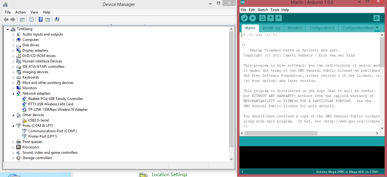
The RAMPS is plugged into the Arduino. there is a green flashing LED on the RAMPS near D10. On the Arudiono, a red LED is permanently on, near the middle of the board.
A green LED next to the red LED on the Arduino is flashing in time to the LED on the RAMPS (which I take to mean they are related).
If I uninstall the mega 2560 driver and then re-scan for ports, Windows automatically installs its own drivers and finds the COM1 port. When I open the Arduino software, it tells me there is a Mega 2560 on COM1- see attached screenshot.
If I try to flash the Marlin firmware, I get the following text in the bottom screen...
Edited 4 time(s). Last edit at 01/10/2015 06:15AM by tim_kberg.
A green LED next to the red LED on the Arduino is flashing in time to the LED on the RAMPS (which I take to mean they are related).
If I uninstall the mega 2560 driver and then re-scan for ports, Windows automatically installs its own drivers and finds the COM1 port. When I open the Arduino software, it tells me there is a Mega 2560 on COM1- see attached screenshot.
If I try to flash the Marlin firmware, I get the following text in the bottom screen...
avrdude: stk500v2_ReceiveMessage(): timeout
avrdude: stk500v2_ReceiveMessage(): timeout
avrdude: stk500v2_ReceiveMessage(): timeout
avrdude: stk500v2_ReceiveMessage(): timeout
avrdude: stk500v2_ReceiveMessage(): timeout
avrdude: stk500v2_ReceiveMessage(): timeout
avrdude: stk500v2_getsync(): timeout communicating with programmer
Edited 4 time(s). Last edit at 01/10/2015 06:15AM by tim_kberg.
|
Re: New I3 build in Wellington January 10, 2015 04:29PM |
Registered: 9 years ago Posts: 118 |
|
Re: New I3 build in Wellington January 11, 2015 03:19PM |
Registered: 10 years ago Posts: 33 |
|
Re: New I3 build in Wellington January 11, 2015 06:14PM |
Registered: 11 years ago Posts: 1,592 |
Un-install the driver that windows put in, then go to the following link..
[www.nextdayreprap.co.uk]
Scroll down to "Documentation", then download one of the build manuals listed. - They are for an i2 I think but that's not important only the PC set-up is what we need.
Then, open up the PDF and scroll down to 10.1, choose the procedure for your Operating system (1st one listed is XP then Win7) then follow the instruction. It may be slightly different on your PC but you will get there ok.
_______________________________________
Waitaki 3D Printer
|
Re: New I3 build in Wellington January 13, 2015 06:07AM |
Registered: 9 years ago Posts: 26 |
IT LIVES!!!!
Turns out that the clone Mega has a different chip (CH340G) which meant I had to look for 3rd party drivers. Found from another forum that I needed to look for CH341 drivers- found one and now its good to go. Turned on the power and all the smoke stayed in the machine the extruder stepper board is not moving the motor (motor works fine if plugged into x axis) so will need to tune the pots then begin the rest of the calibration.
Will do a proper build summary at some point once I have an hour or 3 spare.
Turns out that the clone Mega has a different chip (CH340G) which meant I had to look for 3rd party drivers. Found from another forum that I needed to look for CH341 drivers- found one and now its good to go. Turned on the power and all the smoke stayed in the machine
the extruder stepper board is not moving the motor (motor works fine if plugged into x axis) so will need to tune the pots then begin the rest of the calibration.Will do a proper build summary at some point once I have an hour or 3 spare.
|
Re: New I3 build in Wellington January 23, 2015 08:26PM |
Registered: 11 years ago Posts: 103 |
|
Re: New I3 build in Wellington January 24, 2015 04:13PM |
Registered: 15 years ago Posts: 242 |
You got stung on the RAMPS at hobby king, I buy stuff there too, but if you went here:
[www.dx.com]
the much lower price includes free shipping. Delivery is usually about 3 weeks.
[www.dx.com]
the much lower price includes free shipping. Delivery is usually about 3 weeks.
|
Re: New I3 build in Wellington January 27, 2015 06:18AM |
Registered: 9 years ago Posts: 26 |
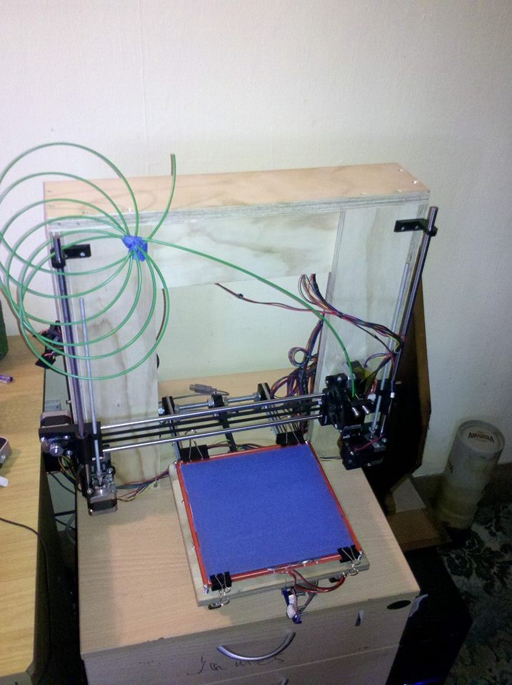
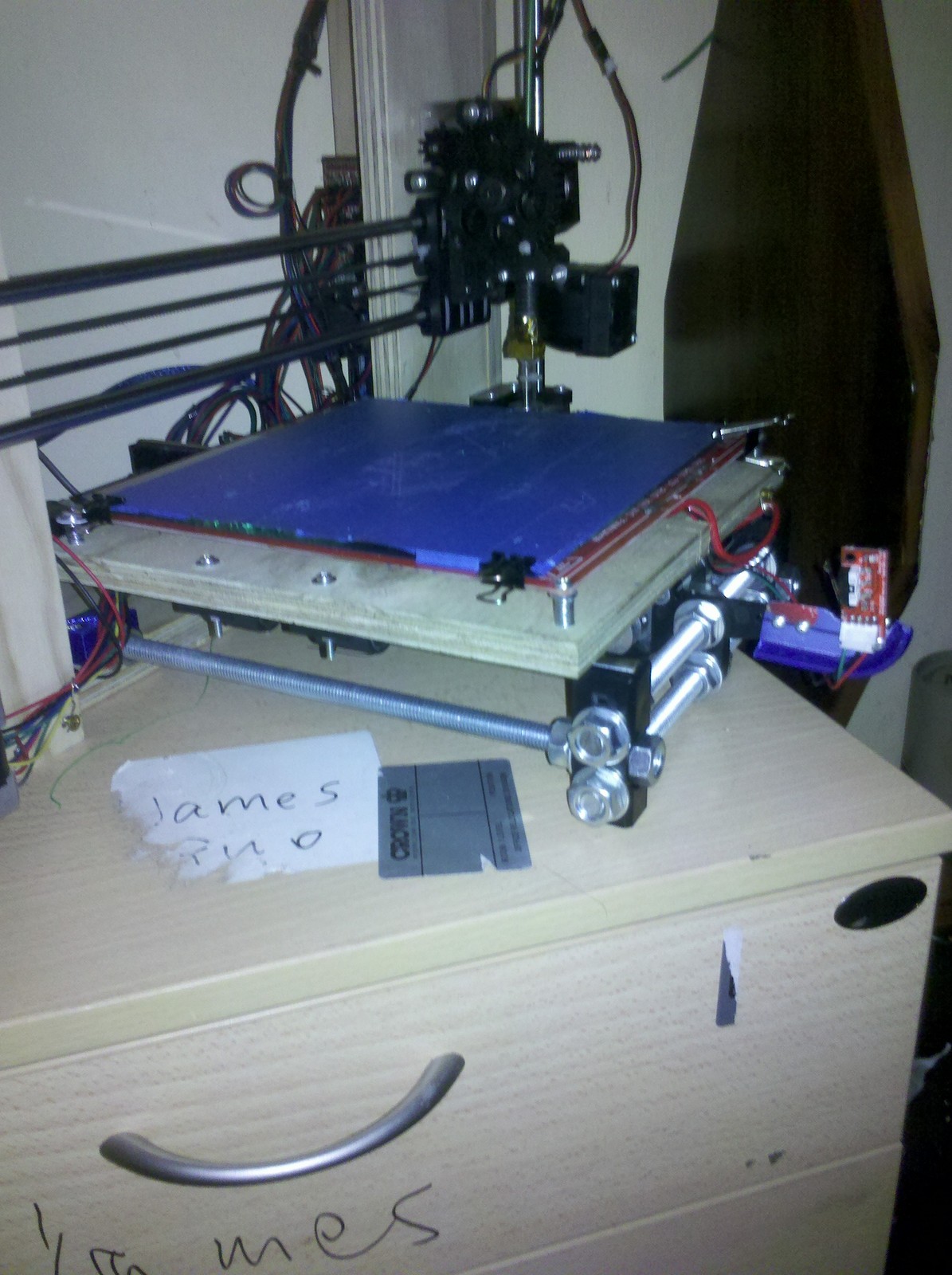
Southrap- I made the frame myself with 17mm ply my builder friend had available- got him to cut it on the table saw.
Attached is a photo just before initial testing.
Grael, I ended up going for this ramps kit: www. aliexpress.com. Seems to be working fine once I got the 3rd party drivers.
Did a couple of prints with reasonable success, but the one I did tonight for some y-carriage clamps/brackets didnt come out 100%. The last 5of 53 layers were offset, like the y-belt had slipped a couple of teeth suddenly. Will troubleshoot this weekend when I have some fee time.
Will get the build summary done this weekend
|
Re: New I3 build in Wellington January 27, 2015 03:16PM |
Registered: 10 years ago Posts: 77 |
Tim
Great to hear things are working well. Y slippage can happen. If your belt is tensioned it is not likely to be skipping teeth. It is more likely that if your bed is supported by 17mm ply (which it looks like from the photo) then it may be a bit on the heavy side for the stepper to accelerate without skipping steps occasionally. You can fix it by either tweaking stepper driver current or decreasing Y acceleration but for my money the real fix is to swap out the bed support plate for something much lighter - either thinner ply or aluminium, or cut a lot of large holes in your existing bed support plate. Even with a light weight bed, I occasionally have problems. My last large print job weighed 350g and it slipped a few mm near the end of the print. Fortunately I managed to salvage the print by taking to it with a chisel to separate it at the slip line, then using short lengths of 1.75mm filament pushed into the 30% hex infil holes to act as keys while I used a dremel to weld the parts back together (like this).
I have also seen slippage caused by strong daggy bits sticking up from the model (particularly after the first solid layer on top of a large area of sparse infil). The extruder nozzle can collide with these dags and the side force can either make the stepper skip or the bed move relative to the bed support (or even make the model break free from the bed). Tweaking extrusion temperatures and fan settings can minimize this risk. A spring loaded bed also helps here - allowing the bed to spring down rather than move sideways.
Pulley slippage on stepper motor shafts is another thing to look out for. It helps if your stepper shafts have flats on them.
Edited 1 time(s). Last edit at 01/27/2015 03:29PM by n.glasson.
My Prusa Mendel i2 inspired Repstrap with welded steel frame: [youtu.be]
And my Smartrap derived Briefcase 3D printer: [youtu.be]
|
Re: New I3 build in Wellington February 06, 2015 05:30AM |
Registered: 9 years ago Posts: 26 |
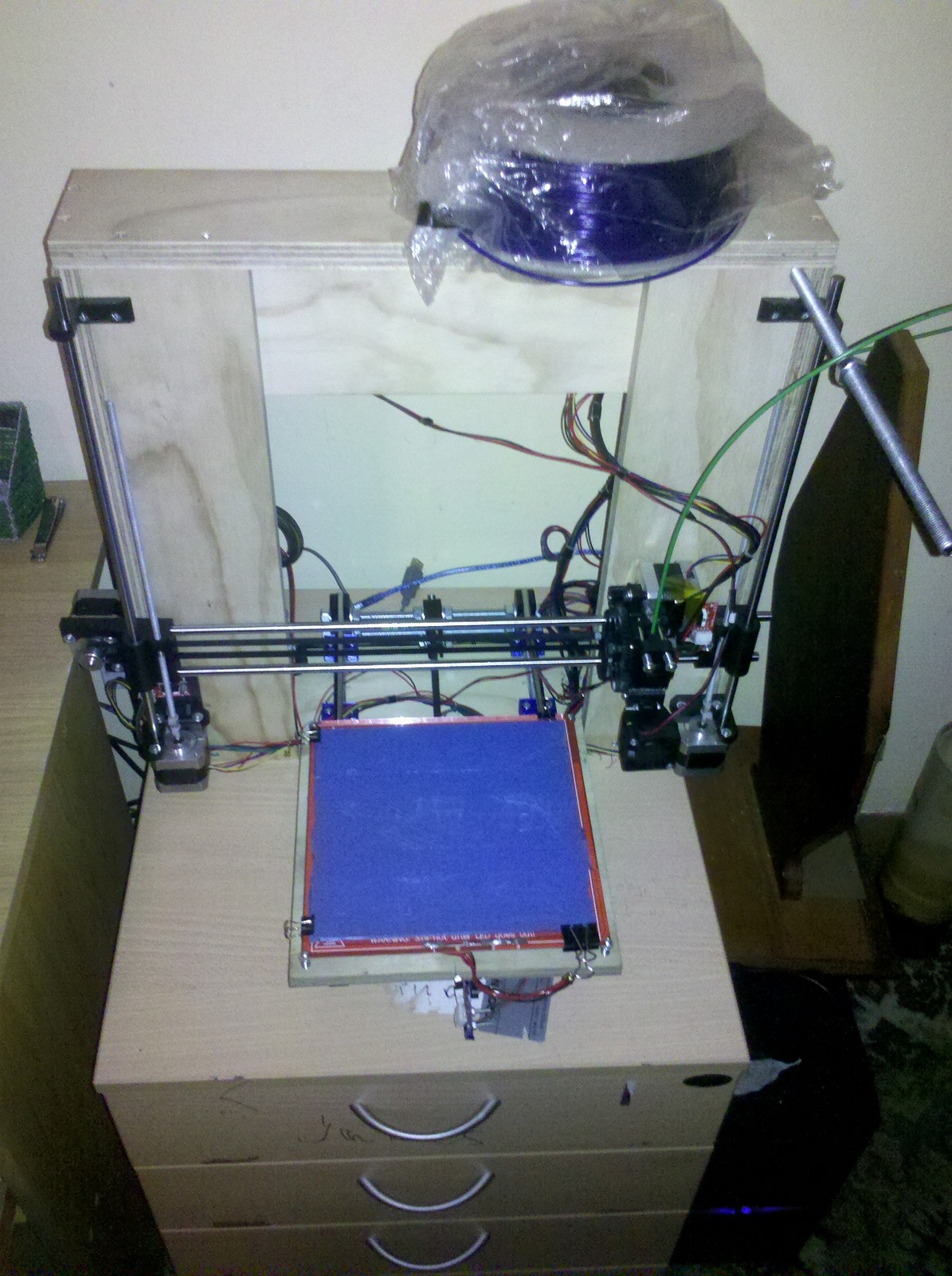
Finally got round to summarising my build. Pretty happy with how things turned out in the end, just need to fine tune for bridging etc, but should probably get a bed fan to get that done properly.
Parts sourcing:
Aliexpress:
5x NEMA 17 motors
PCB heated bed
Linear guide rails. Note that the rods for the y-axis are longer than specified on the reprap wiki, so cut your threaded rod accordingly (got caught out but made it work in the end)
20x LM8UU bearings. At least I have spares
1x Hobbed bolt
Mechanical Endstops + wires
GT2 belt and pulleys
RAMPS 1.4 + MEGA 2560 clone + 5x A4988 steppers + 5x heatsink. Figured out I needed a CH461G driver to get the MEGA working. Just google it.
10x 100K thermistors
Motor/ Endstop/ Thermistor wires. Found this to be rather useful if you dont want to go the way of soldering your own Dupont connectors
Kapton tape
2x 12V, 40mm fans
Replikeo.com: Printed parts (i3 rework)
Hotends.com: 3mm/ 0.4mm nozzle
Coastal Fasteners: Nuts, bolts, washers, threaded rod, C510 springs.
Bunnings:
25mm screws
M3 50mm spring toggle (4x, though you only need 2)
Zip ties
Got my glass from Kelly Glass and Mirror ($10 for one piece, or $16 for 2), but found out after that Affordable Glass in Island bay do it for $5 per piece. A friend cut the frame in 17mm plywood, and the bed in 12mm ply. A colleague gave me a 500W ATX PSU.
The actual build took me a day and a half, or so. I followed a couple of different website: Official i3 Rework page, and This i3 build log- I believe Zerker also posted about it.
A few things I found out:
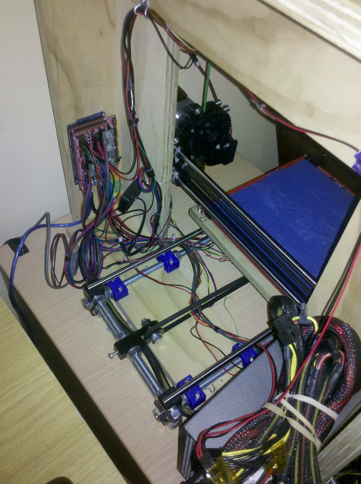
Its probably better to cut your threaded rod after you get the other parts I realised this after putting together the y-carriage and finding out the linear rods were longer than expected. Also could have cut the m5 threaded rod for the z-axis a good 50-80mm longer, and got more build volume. I had cut them to the specified lengths in the wiki page. If this causes hassles later I can always get some more rod, but for now it shouldnt affect me too much.
The plastic parts from Replikeo are for the single plate version, If you are building the box-frame version like I am, you need to get extra parts printed to hold the LM8UU bearings on the bed and to hold the y-carriage to the base of the boxframe. Waitaki printed the bearing brackets for me, and I made a plan with some wire that secured the y-carriage well enough to get things started, then printed some brackets myself to keep things permanently fixed.
The box frame also reduced the distance the bed can travel in the y-direction, due to the offset of the y-carriage clamping points compared to a single plate version. To overcome this I had to off-set my bearing mounts (so half of my bed is unsupported), and extend the end-stop holder for the y-axis with part of an ice-cream lid. I will probably cut a slot in the bed at a later date to counter this. The easiest solution would be to make the bottom piece of the box-frame thinner to reduce the offset of the y-carriage, but I dont have the right tools to do this neatly.
3mm tubing works nicely as z-axis couplers- with the aid of some boiling water. I actually got some from a rexona deo can I had cut up for the aluminium shell works a charm.
Next things to print are a mounting for the RAMPS fan and holder for the PLA reel. I temporarily drilled a hole in the corner and stuck a threaded rod through, still undecided if I will make that a permanent arrangement or not.
Let me know if there is anything else you want to know. See attached pics for a better idea of what I did
Parts sourcing:
Aliexpress:
5x NEMA 17 motors
PCB heated bed
Linear guide rails. Note that the rods for the y-axis are longer than specified on the reprap wiki, so cut your threaded rod accordingly (got caught out but made it work in the end)
20x LM8UU bearings. At least I have spares
1x Hobbed bolt
Mechanical Endstops + wires
GT2 belt and pulleys
RAMPS 1.4 + MEGA 2560 clone + 5x A4988 steppers + 5x heatsink. Figured out I needed a CH461G driver to get the MEGA working. Just google it.
10x 100K thermistors
Motor/ Endstop/ Thermistor wires. Found this to be rather useful if you dont want to go the way of soldering your own Dupont connectors
Kapton tape
2x 12V, 40mm fans
Replikeo.com: Printed parts (i3 rework)
Hotends.com: 3mm/ 0.4mm nozzle
Coastal Fasteners: Nuts, bolts, washers, threaded rod, C510 springs.
Bunnings:
25mm screws
M3 50mm spring toggle (4x, though you only need 2)
Zip ties
Got my glass from Kelly Glass and Mirror ($10 for one piece, or $16 for 2), but found out after that Affordable Glass in Island bay do it for $5 per piece. A friend cut the frame in 17mm plywood, and the bed in 12mm ply. A colleague gave me a 500W ATX PSU.
The actual build took me a day and a half, or so. I followed a couple of different website: Official i3 Rework page, and This i3 build log- I believe Zerker also posted about it.
A few things I found out:
Its probably better to cut your threaded rod after you get the other parts
I realised this after putting together the y-carriage and finding out the linear rods were longer than expected. Also could have cut the m5 threaded rod for the z-axis a good 50-80mm longer, and got more build volume. I had cut them to the specified lengths in the wiki page. If this causes hassles later I can always get some more rod, but for now it shouldnt affect me too much.The plastic parts from Replikeo are for the single plate version, If you are building the box-frame version like I am, you need to get extra parts printed to hold the LM8UU bearings on the bed and to hold the y-carriage to the base of the boxframe. Waitaki printed the bearing brackets for me, and I made a plan with some wire that secured the y-carriage well enough to get things started, then printed some brackets myself to keep things permanently fixed.
The box frame also reduced the distance the bed can travel in the y-direction, due to the offset of the y-carriage clamping points compared to a single plate version. To overcome this I had to off-set my bearing mounts (so half of my bed is unsupported), and extend the end-stop holder for the y-axis with part of an ice-cream lid. I will probably cut a slot in the bed at a later date to counter this. The easiest solution would be to make the bottom piece of the box-frame thinner to reduce the offset of the y-carriage, but I dont have the right tools to do this neatly.
3mm tubing works nicely as z-axis couplers- with the aid of some boiling water. I actually got some from a rexona deo can I had cut up for the aluminium shell
works a charm.Next things to print are a mounting for the RAMPS fan and holder for the PLA reel. I temporarily drilled a hole in the corner and stuck a threaded rod through, still undecided if I will make that a permanent arrangement or not.
Let me know if there is anything else you want to know. See attached pics for a better idea of what I did
|
Re: New I3 build in Wellington February 06, 2015 11:17PM |
Registered: 9 years ago Posts: 118 |
|
Re: New I3 build in Wellington February 06, 2015 11:46PM |
Registered: 10 years ago Posts: 167 |
I thought it was a fillament guide, but I suppose it could be for that too
can you give a bit more detail about how your print bed is attached and the leveling system? I'm having trouble with that on mine, might flag the heatbed all together.
Nice build, looks far cleaner than mysetup, how are your prints going?
can you give a bit more detail about how your print bed is attached and the leveling system? I'm having trouble with that on mine, might flag the heatbed all together.
Nice build, looks far cleaner than mysetup, how are your prints going?
|
Re: New I3 build in Wellington February 09, 2015 09:27PM |
Registered: 9 years ago Posts: 26 |
Clogs, it seems your hat knows a thing or two- I lifted the spool on and off a couple of times and did notice a twist in the frame in the order of 1cm or so. It hadnt affected my prints yet as they have all been low profile. I will try a tall print later this week to see how it fares, but a new spool bracket is definitely a top priority now! Thanks for the heads up- it had never even crossed my mind
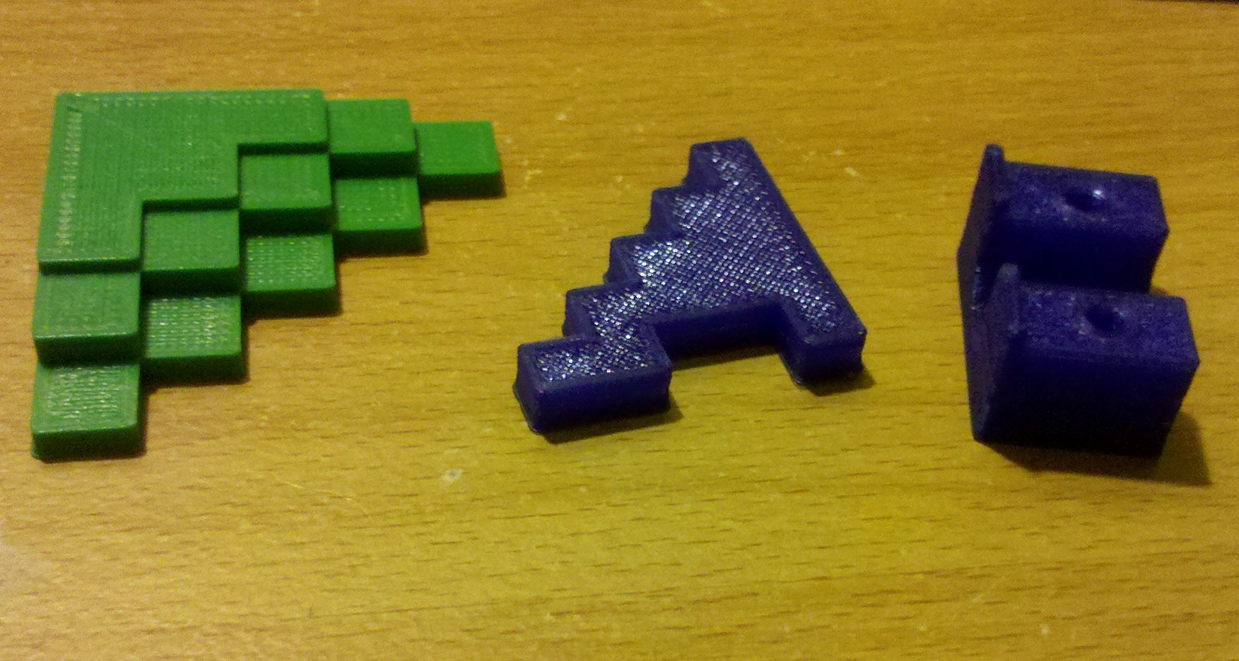
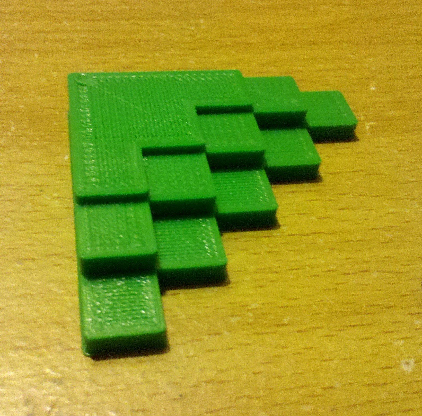
Zerker, I had switched filaments to do the E-steps fine tuning, as using the translucent blue is nigh on impossible to accurately see whether there are minute gaps between the lines or not. Thankfully DiamondAge had sent some other sample colours along too. Have attached a couple of the calibration pieces.- pretty happy when the basic settings are used (though I had to slow down the speed from the Slic3r defaults for now). Phone camera is pretty terrible, but the green one is done with 0.2mm layer height, and I stopped it early so you can see the infill at 95%.
My only problem is that the filament extrusion speed seems to vary during filling, leading to light/ dark patches with the translucent filament, or slight gaps with the opaque filament. Not sure if that is due to the hobbed bolt not being uniform or not- I cant seem to pin it down to a particular rotation of the extruder gear or not. Time for trial and error...
The bed is just attached with 4x M3 30mm machine screws and C510 springs. It seems to be working pretty well, though one corner of the plywood was 3mm higher than the other 3, so I had to really crank that down to get it level. Might do a large single layer print tonight to see how the relative levels are faring. I have standard nuts at the moment, though I may get some Nylock ones to make sure that vibrations dont mess things up in the long run.
Edited 1 time(s). Last edit at 02/10/2015 05:01AM by tim_kberg.
Sorry, only registered users may post in this forum.