Marlin 2.0 Fan PWM frequency too low
Posted by fdumi
|
Marlin 2.0 Fan PWM frequency too low October 25, 2020 06:19AM |
Registered: 3 years ago Posts: 4 |
Hello everybody,
I changed the cooling system (hotend+part cooling) on my Ender 3 Pro, and in this process I also changed the stock fans with some Sunon MF40202VX-1000U-A99, 40x40x20 fans.
I am now facing the current problem: the part cooling fans don't run unless the PWM is higher than 248/252 (stock firmware).
I flashed Marlin 2.0.7.2 on the board (Creality3D v1.1.4), but the problem still persists (for PWM lower than 98% the fans don't run). I then checked the pin on the controller which controls the cooling fans and saw it's OC0B, so the PWM is controlled by Timer0 of the ATmega1284PU.
I measured the frequency at 976.6Hz on my osciloscope. Increasing the PWM to the level at which the fans start rotating showed me that the fans have some sort of under voltage lock-out, and if the "off" time of the PWM is longer than 20us then the fans will not start / will turn off. This would have been ok since Timer0 could achieve a PWM period under 20us with the correct configuration.
I then started searching through the Marlin source code and found out that Timer0 also controls the temperature PID controller and other SW algorithms, so changing the timer frequency is not permitted. I then thought that I can move all the SW control functions to Timer2 and leave Timer0 only for the PWM output and set a frequency of 62.5kHz.
My actual problem is that the Timer configuration registers are adressed from multiple files in the Marlin firmware (I found until now timer.h and temperature.cpp that adress the registers directly). I don't know where to look in the software for the required changes because of the abstractized approach.
Has someone had this issue, or is there someone with more experience with the Marlin source code who can guide me to where/what should I change in the source code?
P.S.: I can confirm that the low PWM frequency is the issue. I have tested he Sunon fans on a PCB I designed, which used 31.25kHz for PWM-ing a motor. On that PCB I can adjust the speed of the fans without any problems.
Edited 2 time(s). Last edit at 10/25/2020 06:20AM by fdumi.
|
Re: Marlin 2.0 Fan PWM frequency too low October 25, 2020 09:39AM |
Admin Registered: 13 years ago Posts: 7,000 |
|
Re: Marlin 2.0 Fan PWM frequency too low October 25, 2020 12:24PM |
Registered: 3 years ago Posts: 4 |
|
Re: Marlin 2.0 Fan PWM frequency too low October 25, 2020 03:52PM |
Admin Registered: 11 years ago Posts: 3,096 |
Won't it be more like a low-pass filter? Or like averaging out the voltage?
I don't think adding a cap with a fan to increase pwm sensitivity will do that much damage.
http://www.marinusdebeer.nl/
I don't think adding a cap with a fan to increase pwm sensitivity will do that much damage.
http://www.marinusdebeer.nl/
|
Re: Marlin 2.0 Fan PWM frequency too low October 25, 2020 08:21PM |
Registered: 3 years ago Posts: 4 |
Offtopic:
A RC low pass filter would presume the existance of a considerable amount of series resistance. The ESR of the capacitor and the wire resistance is not that much; demonstration below.
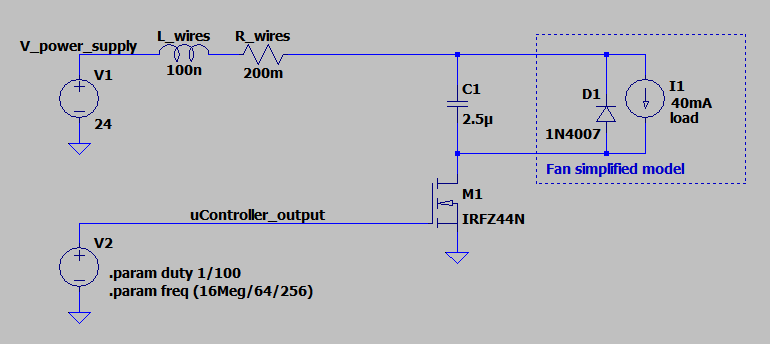
So let's say one implements a capacitor in parallel with a motor, which is driven by a low-side MOSFET, as it is in the case of the MELZI board. The diagram qould look something like this:
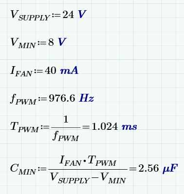
Here, L_wires and R_wires would represent the resistance of the wires from the fan to the power supply (not measured but the values should be in this range). V1 is the power supply and V2 is the controller output pin. I don't know what MOSFET is exactly on the PCB as it has a heatsink glued on top of it; I used a generic IRFZ44N for this simulation. Before I show the simulation results, let's do some calculations. Let's say the nominal supply voltage is 24V and the minimum voltage for the fan to operate is 8V (as per the datasheet). The current consumption is around 40mA measured and the frequency is around 976.6Hz measured. Therefore the required capacitor would be (calculations done in Mathcad, so the units are correct):
2.5uF is not a standard value and the next higher standard value is 3.3uF, but let's go with 2.5uF. Let's consider now that the 2.5uF capacitor is an electrolytic cap and has an ESR of 2 ohms (usual for a "normal" quality electrolytic capacitor).
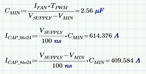
Disregarding the ESR and considering a slow MOSFET switch-on time of 100ns, we get the following theoretical maximum current spike that the capacitor would draw for a charge from 0V to 24V, and from 8V to 24V:
Indeed these current values are theoretical because they assume ideal comoponents. With this calculation I just wanted to demonstrate that good quality capacitors can gulp a lot of current.
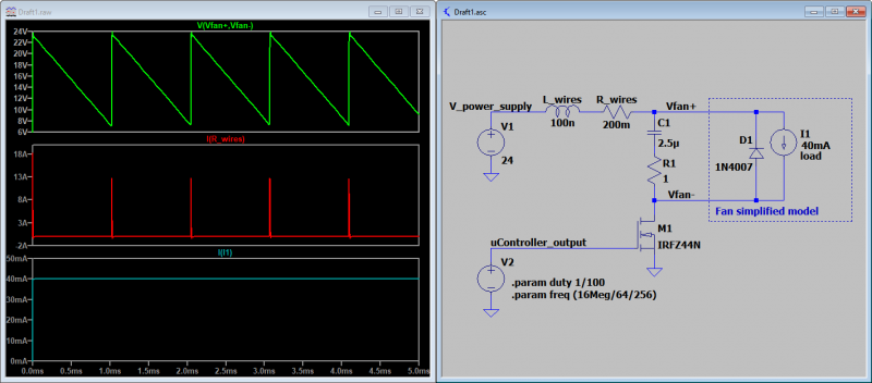
Now, for the simulation which is a bit closer to real life:
As you can see, even with "real" components we still get current spikes in excess of 10A. Yes, there are capacitors on the PCB that can supply that short current pulses, but at the cost of faster component degradation due to heating.
Does a capacitor in parallel with the fan solve the issue? Maybe, I have never tried something like this and I don't consider it a solution, as it is a bad idea.
Ontopic:
I still believe the SW implementation is not good. I actually searched on google for papers on PWM frequency for fan control and found that in PCs they use either really low frequencies (sub 100Hz) of higher than 20kHz so the audible noise is eliminated.
Quote
Ohmarinus
Won't it be more like a low-pass filter? Or like averaging out the voltage?
A RC low pass filter would presume the existance of a considerable amount of series resistance. The ESR of the capacitor and the wire resistance is not that much; demonstration below.
So let's say one implements a capacitor in parallel with a motor, which is driven by a low-side MOSFET, as it is in the case of the MELZI board. The diagram qould look something like this:
Here, L_wires and R_wires would represent the resistance of the wires from the fan to the power supply (not measured but the values should be in this range). V1 is the power supply and V2 is the controller output pin. I don't know what MOSFET is exactly on the PCB as it has a heatsink glued on top of it; I used a generic IRFZ44N for this simulation. Before I show the simulation results, let's do some calculations. Let's say the nominal supply voltage is 24V and the minimum voltage for the fan to operate is 8V (as per the datasheet). The current consumption is around 40mA measured and the frequency is around 976.6Hz measured. Therefore the required capacitor would be (calculations done in Mathcad, so the units are correct):
2.5uF is not a standard value and the next higher standard value is 3.3uF, but let's go with 2.5uF. Let's consider now that the 2.5uF capacitor is an electrolytic cap and has an ESR of 2 ohms (usual for a "normal" quality electrolytic capacitor).
Disregarding the ESR and considering a slow MOSFET switch-on time of 100ns, we get the following theoretical maximum current spike that the capacitor would draw for a charge from 0V to 24V, and from 8V to 24V:
Indeed these current values are theoretical because they assume ideal comoponents. With this calculation I just wanted to demonstrate that good quality capacitors can gulp a lot of current.
Now, for the simulation which is a bit closer to real life:
As you can see, even with "real" components we still get current spikes in excess of 10A. Yes, there are capacitors on the PCB that can supply that short current pulses, but at the cost of faster component degradation due to heating.
Does a capacitor in parallel with the fan solve the issue? Maybe, I have never tried something like this and I don't consider it a solution, as it is a bad idea.
Ontopic:
I still believe the SW implementation is not good. I actually searched on google for papers on PWM frequency for fan control and found that in PCs they use either really low frequencies (sub 100Hz) of higher than 20kHz so the audible noise is eliminated.
Quote
fdumi
Has someone had this issue, or is there someone with more experience with the Marlin source code who can guide me to where/what should I change in the source code?
|
Re: Marlin 2.0 Fan PWM frequency too low October 30, 2020 04:49AM |
Registered: 3 years ago Posts: 4 |
github discussion
So basically, if the fans are controlled by the same timer as the one used for the temperature control algorithms, it's pretty much impossible to have the fan PWM at any frequency higher than the standard 976Hz.
So basically, if the fans are controlled by the same timer as the one used for the temperature control algorithms, it's pretty much impossible to have the fan PWM at any frequency higher than the standard 976Hz.
|
Re: Marlin 2.0 Fan PWM frequency too low November 02, 2020 11:51AM |
Registered: 7 years ago Posts: 619 |
It was a pretty common practice in RC car racing to place .1uF caps between each motor tap and the metal housing and one between the motor taps with DC brushed motors. This eliminated a raft of issues with PWM motor controllers. So, yeah, it helps with DC brushed motors. I don't know about brushless motors however.
DLC
Kits: Folgertech Kossel 2020 upgraded E3Dv6, Anet A8 upgraded E3Dv6, Tevo Tarantula enhanced parts and dual-head, TronXY X5SA Pro(E3DHemera).
Scratch: Large bed Cartesian, exchangeable heads, Linear slide Delta, Maker-Beam XL Micro Delta, 220x220CoreXY.
DLC
Kits: Folgertech Kossel 2020 upgraded E3Dv6, Anet A8 upgraded E3Dv6, Tevo Tarantula enhanced parts and dual-head, TronXY X5SA Pro(E3DHemera).
Scratch: Large bed Cartesian, exchangeable heads, Linear slide Delta, Maker-Beam XL Micro Delta, 220x220CoreXY.
Sorry, only registered users may post in this forum.


