Setup Marlin on DIY printer - Mega2560 TCM2209 z-probe
Posted by cysign
|
Re: Setup Marlin on DIY printer - Mega2560 TCM2209 z-probe July 24, 2021 05:41PM |
Registered: 8 years ago Posts: 90 |
Finally added a part cooling fan for the first extruder to start printing PLA. Now I need to remove the ABS. I've read I should set temperature to the new filaments melting temperature and pull out the old filament.
Working on two things right now:
1. where on my Ramps 1.6 shall I connect my part cooling fan (it alreads is buffert by an BUZ11 with an flyback diode - so no current issue and no inductive voltage peaks are expected). But on which pin shall I connect the part cooling fan?
Which string do I have to search for on the Configuration_adv.h?
//edit:
//edit2: looks like it has to be:
2. I remember I couldn't activate my runout sensors as it triggers filamentchange always. So I disabled it month ago...to get started with my 3d printer.
Now I'd like to solve the problem. I guess it has to be a double seizure on a pin.
But I'm not sure about this. Any ideas?
Current config files (config, config_adv, pins_ramps) are located here:
www.digitalinventions.de/files/pics/3Dprinter/20210724_IronBot_configfiles_before_partcoolingfan.zip
Edited 5 time(s). Last edit at 07/24/2021 07:01PM by cysign.
Working on two things right now:
1. where on my Ramps 1.6 shall I connect my part cooling fan (it alreads is buffert by an BUZ11 with an flyback diode - so no current issue and no inductive voltage peaks are expected). But on which pin shall I connect the part cooling fan?
Which string do I have to search for on the Configuration_adv.h?
//edit:
// RAMPS 1.4 DIO 4 on the servos connector
#ifndef FIL_RUNOUT_PIN
  #define FIL_RUNOUT_PIN                       11
  #define FIL_RUNOUT2_PIN                      40  // was pin 6 before, but I want to use the pwm-pin for the part cooling fan now
//edit2: looks like it has to be:
/**
 * Part-Cooling Fan Multiplexer
 *
 * This feature allows you to digitally multiplex the fan output.
 * The multiplexer is automatically switched at tool-change.
 * Set FANMUX[012]_PINs below for up to 2, 4, or 8 multiplexed fans.
 */
#define FANMUX0_PIN 6
#define FANMUX1_PIN -1
#define FANMUX2_PIN -1
2. I remember I couldn't activate my runout sensors as it triggers filamentchange always. So I disabled it month ago...to get started with my 3d printer.
Now I'd like to solve the problem. I guess it has to be a double seizure on a pin.
But I'm not sure about this. Any ideas?
Current config files (config, config_adv, pins_ramps) are located here:
www.digitalinventions.de/files/pics/3Dprinter/20210724_IronBot_configfiles_before_partcoolingfan.zip
Edited 5 time(s). Last edit at 07/24/2021 07:01PM by cysign.
|
Re: Setup Marlin on DIY printer - Mega2560 TCM2209 z-probe July 25, 2021 07:49AM |
Registered: 8 years ago Posts: 90 |

|
Re: Setup Marlin on DIY printer - Mega2560 TCM2209 z-probe July 25, 2021 08:01AM |
Admin Registered: 13 years ago Posts: 7,001 |
|
Re: Setup Marlin on DIY printer - Mega2560 TCM2209 z-probe July 25, 2021 08:11AM |
Registered: 8 years ago Posts: 90 |
All right, I see the problem.
Fixed it, but testing using the M106 command doesn't work.
What's the entry for ading a second part cooling fan?
FAN_PIN1? FAN_PIN2?
By the way: is it a good time to switch back from bugfix release to stable release? Had to use the bugfix release to get HD44780 on PCF8574 running and to avoid the z-layer problem on the bottom 4.65mm (0-4.65mm were nearly printed in one layer - bugfixrelease fixed it). I have no clue how to see if this is fixed now... just installing casual release and test it?
Edited 1 time(s). Last edit at 07/25/2021 08:23AM by cysign.
Fixed it, but testing using the M106 command doesn't work.
What's the entry for ading a second part cooling fan?
FAN_PIN1? FAN_PIN2?
14:08:25.727 > start
14:08:25.728 > Marlin bugfix-2.0.x
14:08:25.728 >
14:08:25.728 > echo: Last Updated: 2020-12-30 | Author: CySign
14:08:25.730 > echo:Compiled: Jul 25 2021
14:08:25.732 > echo: Free Memory: 3288  PlannerBufferBytes: 1200
M106
14:08:31.182 > echoD card ok
14:08:31.355 > echo:Unknown command: "M106"
14:08:31.355 > ok
M106 S150
14:08:46.236 > echo:Unknown command: "M106 S150"
14:08:46.238 > ok
By the way: is it a good time to switch back from bugfix release to stable release? Had to use the bugfix release to get HD44780 on PCF8574 running and to avoid the z-layer problem on the bottom 4.65mm (0-4.65mm were nearly printed in one layer - bugfixrelease fixed it). I have no clue how to see if this is fixed now... just installing casual release and test it?
Edited 1 time(s). Last edit at 07/25/2021 08:23AM by cysign.
|
Re: Setup Marlin on DIY printer - Mega2560 TCM2209 z-probe July 25, 2021 09:39AM |
Admin Registered: 13 years ago Posts: 7,001 |
|
Re: Setup Marlin on DIY printer - Mega2560 TCM2209 z-probe August 16, 2021 12:38PM |
Registered: 8 years ago Posts: 90 |
Next problem occurs.
I need to print some parts which contain a proper scaling.
But my printed part seems to be too small on z-axis:
(please ignore the red markup on the left....it's the wrong value I marked)
Might this be an issue depending on auto bed-leveling?
Or is it just a wrong value for steps on the z-axis?
My current configfiles are here:
digitalinventions.de/files/pics/3Dprinter/20210816_IronBot_configFiles.zip
As the wrong scaling appears during the first 50 layers, it might be an issue with auto-bedleveling I guess.
The part I try to print is the 6inch drumpad from this url:
[www.thingiverse.com]
Edited 3 time(s). Last edit at 08/16/2021 01:09PM by cysign.
I need to print some parts which contain a proper scaling.

But my printed part seems to be too small on z-axis:


(please ignore the red markup on the left....it's the wrong value I marked)

Might this be an issue depending on auto bed-leveling?
Or is it just a wrong value for steps on the z-axis?
My current configfiles are here:
digitalinventions.de/files/pics/3Dprinter/20210816_IronBot_configFiles.zip
As the wrong scaling appears during the first 50 layers, it might be an issue with auto-bedleveling I guess.
The part I try to print is the 6inch drumpad from this url:
[www.thingiverse.com]
Edited 3 time(s). Last edit at 08/16/2021 01:09PM by cysign.
|
Re: Setup Marlin on DIY printer - Mega2560 TCM2209 z-probe August 17, 2021 07:19PM |
Registered: 4 years ago Posts: 90 |
If you are a Marlin user, you could change DEFAULT_LEVELING_FADE_HEIGHT in Configuration.h for a smaller value (default = 10mm).
Maybe it's the camera optics , but the picture shows a bent corner. Looks like the bottom is warped. This could be part of the problem. But your part height being off by 0.5mm (Cura Measure Tool vs calipers), chances are your steps/mm have to be adjusted.
On my side, I never design hexagons for nuts with this orientation. I always design them so top is bridged (horizontal). Because of sagging on 60° overhangs.
[EDIT] do you print infill before walls, and/or outer wall before inner wall ?
Edited 1 time(s). Last edit at 08/17/2021 07:22PM by yet-another-average-joe.
|
Re: Setup Marlin on DIY printer - Mega2560 TCM2209 z-probe August 18, 2021 12:37PM |
Registered: 8 years ago Posts: 90 |
Trying 2mm right now. Just compiled and uploaded Marlin using the new valueQuote
yet-another-average-joe
change DEFAULT_LEVELING_FADE_HEIGHT in Configuration.h for a smaller value (default = 10mm).

I think it might be this setting, as if it were too less steps on z-axis in general, I would have way less than the missing distante on the first layers...
but the picture shows a bent corner. Looks like the bottom is warped.
Where exactly do you mean?
Could you mark the image?
Good question, next one.Quote
yet-another-average-joe
[EDIT] do you print infill before walls, and/or outer wall before inner wall ?
To be honest: I don't know.
It has to be a cura setting. For which one shall I go?
//Edit: Found the setting: Walls => Outer before inner walls. It is disabled.
Edited 1 time(s). Last edit at 08/18/2021 12:43PM by cysign.
|
Re: Setup Marlin on DIY printer - Mega2560 TCM2209 z-probe August 18, 2021 02:58PM |
Registered: 8 years ago Posts: 90 |
A DEFAULT_LEVELING_FADE_HEIGHT of 2 didn't do the trick.
So next I'm going to print some Z-axis test prints to align steps/mm.
What else could I do?
Just checked my Z-level on a random point on my printing area. My z-sensor activated on 1.4mm. When in home position my printer is at 222mm on z-axis.
Might this be the issue?
So starting with layer 1 on 1.4mm and then it might try to get the layers aligned until a proper value?
Shall I set my z-axis to 222mm-1.4mm = 220.6mm on Marlin?
Edited 1 time(s). Last edit at 08/18/2021 03:05PM by cysign.
|
Re: Setup Marlin on DIY printer - Mega2560 TCM2209 z-probe August 18, 2021 03:27PM |
Registered: 8 years ago Posts: 90 |

|
Re: Setup Marlin on DIY printer - Mega2560 TCM2209 z-probe August 18, 2021 09:53PM |
Registered: 4 years ago Posts: 90 |
If your model is 60.5mm and you print 59mm, you have to increase Z-steps by 2.5%, or multiply by 1.0254 : if 400 steps/mm, you could test with 410 ; it has nothing to do with Z-offset.
With the overhang you have on the hexagon because of the design, printing inner wall before outer wall is probably better : inner before outer is better for large overhangs (60° !), but you loose some precision. In extreme overhangs, infill could be printed before walls. But it's even worse for precision. Models should be designed so they can be printed in this order : outer wall then inner wall, then infill : gives much nicer parts.
On your website, we can see you have some machine tools. If you have machine tools, you also have at least one DTI. You could also verify that a 10mm move gives a 10mm reading, and test at different heights, using a 123 block on the bed : at bed height, at 25mm, 50mm and 75mm A couple years ago, I got a used swiss made 50mm DTI as a poor man's DRO for my lathes. It is extremely usefull for 3D printer traming and calibration ! Longer is better ! I also compared the Z moves on the left and right sides using two DTIs and discovered that the left and right didn't move exactly the same (+-0.1mm, not in synch, on each side = 0.2mm difference at worst). (I also have a dual Z, mechanical only, one motor). Cheap chinese leadscews accuracy and linearity is... cheap !
Your printer design is interesting (Z motors on the X axis and isostatic leadscrews arrangements, welded frame, built like a tank). Welding perfectly flat and square is extremely difficult. Does the X axis smoothly moves up and down ? (perfect parallelism, no skew ?) Never seen this design on a 3D printer, it's more common on CNC routers and plasma cutters AFAIK.
You can heat the nut before inserting it. And as long as all the parts are the same height, it probably does not really matter if the drum is 60.5 or 59mm. I'd print everything, make the drum pad, and fine adjust the printer later !!! Or you'll have to throw this print away...
It seems the bottom of the print (picture 82.jpg) is not flat. Looks like it's warped and there was a problem with bed adhesion. Just below the hexagon. This could explain the problem with hexagon and the nut not fitting well.
|
Re: Setup Marlin on DIY printer - Mega2560 TCM2209 z-probe August 19, 2021 01:20PM |
Registered: 8 years ago Posts: 90 |
I'll try this right nowQuote
yet-another-average-joe
If your model is 60.5mm and you print 59mm, you have to increase Z-steps by 2.5%, or multiply by 1.0254 : if 400 steps/mm, you could test with 410 ; it has nothing to do with Z-offset.
Looks like this is the default setting for Cura.Quote
yet-another-average-joe
printing inner wall before outer wall is probably better
I'm going to print a z-axis calibration part...but I didn't find a good one to calibrate z-axis. Any suggestions?Quote
yet-another-average-joe
On your website, we can see you have some machine tools. If you have machine tools, you also have at least one DTI. You could also verify that a 10mm move gives a 10mm reading, and test at different heights, using a 123 block on the bed : at bed height, at 25mm, 50mm and 75mm
If the screws are my problem, I'll change them. But first I have to check this.Quote
yet-another-average-joe
Cheap chinese leadscews accuracy and linearity is... cheap !
Just wanted to start building the machine...and a welded frame sounded better than one based on wood (at least as far as I can't cnc mill it). So I just started.Quote
yet-another-average-joe
Your printer design is interesting (Z motors on the X axis and isostatic leadscrews arrangements, welded frame, built like a tank). Welding perfectly flat and square is extremely difficult. Does the X axis smoothly moves up and down ? (perfect parallelism, no skew ?) Never seen this design on a 3D printer, it's more common on CNC routers and plasma cutters AFAIK.
But my z-motor is on top of the machine. Both leadscrewa are driven with a belt using one single motor.
That's my Plan B...but as I would like to print many edrum-pads...that's the worst case. I'd better align my machine properly before printing many edrum padsQuote
yet-another-average-joe
You can heat the nut before inserting it. And as long as all the parts are the same height, it probably does not really matter if the drum is 60.5 or 59mm. I'd print everything, make the drum pad, and fine adjust the printer later !!! Or you'll have to throw this print away...
It just looks like this on the image. What seems to be curved, is curved. It's the outer wall - which is a radius somewhere close to 6". The bottom looks nearly perfectly flat (except the two parts where my BuildTak is damaged...I'm going to replace it as soon as I get decent printing results).Quote
yet-another-average-joe
It seems the bottom of the print (picture 82.jpg) is not flat. Looks like it's warped and there was a problem with bed adhesion. Just below the hexagon. This could explain the problem with hexagon and the nut not fitting well.
Edited 1 time(s). Last edit at 08/19/2021 01:23PM by cysign.
|
Re: Setup Marlin on DIY printer - Mega2560 TCM2209 z-probe August 19, 2021 03:51PM |
Registered: 8 years ago Posts: 90 |
Crazy things happen. Changed from 400 to 410steps/mm on z-axis. But instead of getting higher, the new print is even taller.
So might I loose steps on z-axis? As feedrate (mm/s) is the same as before, but steps/mm have changed, might this result in more steps/s while losing steps? Acceleration is 200. X/Y axis work well using 2000,but those are belt driven.
mm/s on my z-axis currently is set to 12mm/s...which might be too much. In configfile it was 5mm/s. I adjusted it during the time, as I couldn't figure out any problems.
Edited 2 time(s). Last edit at 08/19/2021 04:18PM by cysign.
So might I loose steps on z-axis? As feedrate (mm/s) is the same as before, but steps/mm have changed, might this result in more steps/s while losing steps? Acceleration is 200. X/Y axis work well using 2000,but those are belt driven.
mm/s on my z-axis currently is set to 12mm/s...which might be too much. In configfile it was 5mm/s. I adjusted it during the time, as I couldn't figure out any problems.


Edited 2 time(s). Last edit at 08/19/2021 04:18PM by cysign.
|
Re: Setup Marlin on DIY printer - Mega2560 TCM2209 z-probe August 19, 2021 07:36PM |
Registered: 4 years ago Posts: 90 |
Weird issue... The first 10mm or so of your parts appear as if they were squished. Right ?
Steps could be lost if the X-axis is hard to move upwards, and/or if the driver Vref (current) is too low ; or belt could be skipping tooth ; also see pulleys grubscrews and belt tension).
But if you are loosing steps or skipping tooth, you'd have measurable overextrusion as well. Plastic has to go somewhere.
For Z-calibration this can be quickly done with some cylinders in vase mode ("spiral" in Cura), resized in Cura : measuring them you'll have to do the math so you get the right steps/mm ; quick and easy with the Cura "Calibration Shapes" plugin. Steps/mm shouldn't be too different from the calculated value.
Another test : repeatability ; measuring a series of small cylinders (same g-code) ; with vase mode, the test will require very few material. (cylinders can be printed fast at constant speed)
OK, now I understand the cinematics. I missed "48.jpg" on your web page ! It's more conventional ! (Prusa Mendel style, 1 motor at top, dual Z with a sync belt and a tensionner). I thought you were using motors with nuts in the rotor (I've seen pictures of machines with a similar arrangement).
Leadscrews : I fear they are all more or less the same ! It's very unlikely they could be off by 1mm for 10mm. 0.1mm precision is enough for what we can do with our 3D printers (but a bit disturbing when we are used to parts with one order of magnitude better precision while turning or milling !).
No reason the Z feedrate is related with the problem.
I would make the two Z nuts free, and move the X-axis assembly from bottom to top by hand, to be sure it moves up and down smoothly. I had such a problem a couple years ago, this is why I'm thinking of that (misalignment, but was with rollers + extrusions).
Welded structure could release some tension after drilling and grinding, and hence warp, ruining rods alignments...
The issue looks like it's not firmware related, but mechanical.
|
Re: Setup Marlin on DIY printer - Mega2560 TCM2209 z-probe August 20, 2021 12:54PM |
Registered: 8 years ago Posts: 90 |
|
Re: Setup Marlin on DIY printer - Mega2560 TCM2209 z-probe August 20, 2021 07:57PM |
Registered: 4 years ago Posts: 90 |
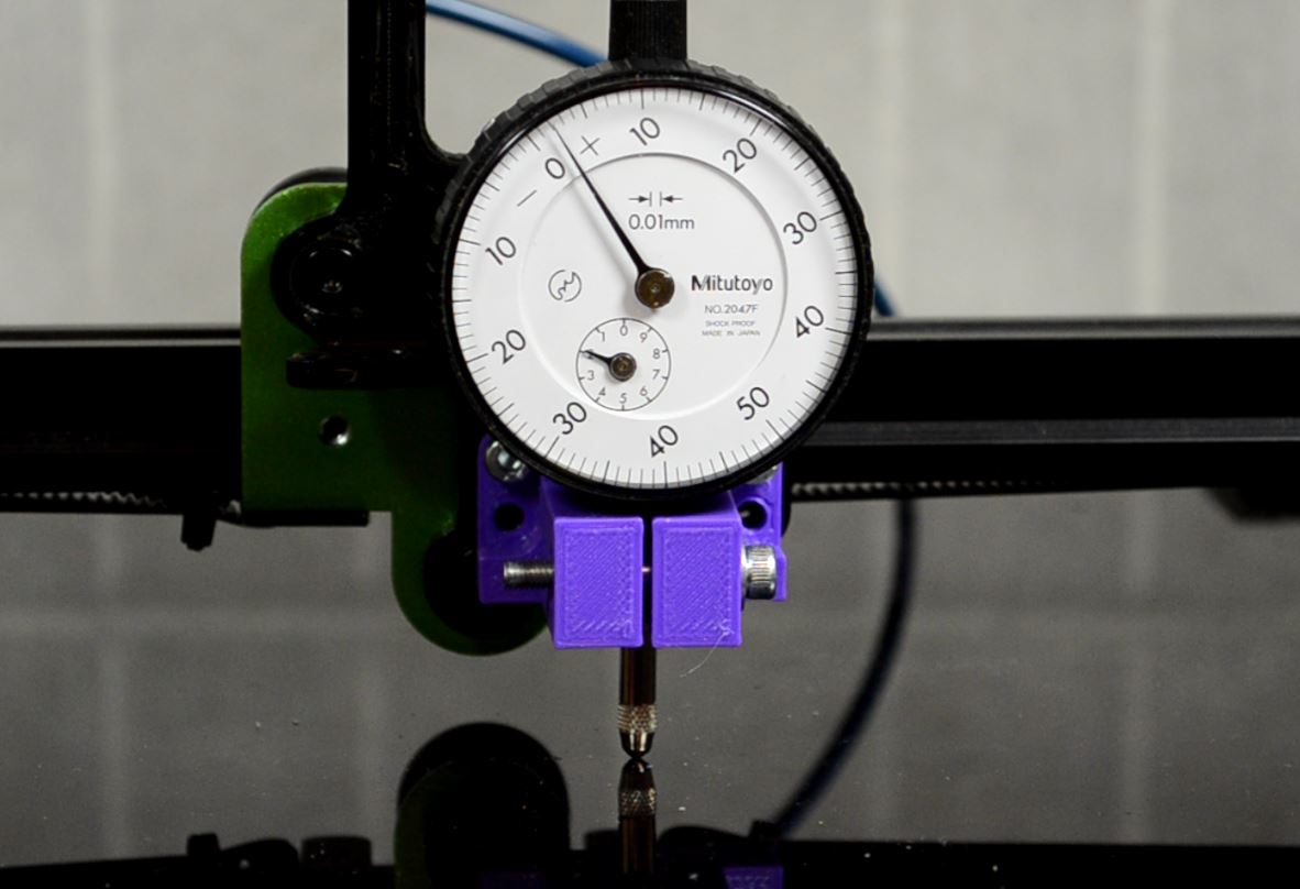
You must use a axial DTI, touching the bed, so you measure Z moves against what marlin displays.
Do it at x=0, x=bed_width/2, x=bed_width. The X axis have to be where it seats when printing the first layer. Then move upwards mm by mm with Marlin. Compare the readings. You will know if the first 10mm are OK.
You will have to make an attachment so you can replace the hotend with the DTI.
Moving the X carriage from left to right, you will be able to verify the parallelism between the bed and the X axis.
Like so (see attached picture) :
|
Re: Setup Marlin on DIY printer - Mega2560 TCM2209 z-probe August 21, 2021 09:55AM |
Registered: 8 years ago Posts: 90 |
|
Re: Setup Marlin on DIY printer - Mega2560 TCM2209 z-probe September 18, 2021 03:00PM |
Registered: 8 years ago Posts: 90 |


Sorry, only registered users may post in this forum.