Idiot's guide to getting a bltouch working.
Posted by Dust
|
Idiot's guide to getting a bltouch working. January 20, 2021 08:06PM |
Admin Registered: 13 years ago Posts: 7,000 |

Some basics:
The bltouch has two parts from a firmware perspective.
a) Control, often called servo. This consists of 3 wires. Red is +5v, Yellow is signal and either a Brown or Black is GND. The control signal is PWM and is treated just like a servo.
b) Trigger. 2 wires, Black is GND and White is the signal.
First step is wiring the bltouch to your controller.
All controllers are different. but they can have a dedicate bltouch plug
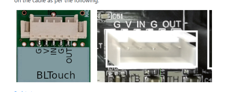
eg the creality V4 series boards

G V and IN are the control pins, G and OUT are the trigger pins.
The board may also have a dedicated probe plug, eg the SKR 1.4
Older boards use servo plugs and endstops plugs.
Creality added a annother option the PIn 27 board.

This board plugs into the LCD connector and disconnect the buzzer to use the PWM pin for the bltouch control/servo plug.
NB There are several different type of bltouchs with different wiring
You have to make sure your wiring matches what your board needs.
Second step you must tell the Marlin firmware how you have the bltouch plugged in
If your trigger is plugged into the Z_min endstop plugs you must set
#define Z_MIN_PROBE_USES_Z_MIN_ENDSTOP_PIN
if your trigger is plugged into a dedicated probe port you must make sure Z_MIN_PROBE_USES_Z_MIN_ENDSTOP_PIN is disabled
eg //#define Z_MIN_PROBE_USES_Z_MIN_ENDSTOP_PIN
and enable USE_PROBE_FOR_Z_HOMING (if you don't have a real Z endstop and are using the probe)
eg #define USE_PROBE_FOR_Z_HOMING
If your using a Pin 27 Board you must enable HAS_PIN_27_BOARD
eg add #define HAS_PIN_27_BOARD to your Configuration.h
NB at this time this only works on Creality V4 Controllers.
Common issues:
1) On power up Bltouch extends and retracts it probe, but wont do it again
This is a issue with the Control/servo plug or configuration. Most conmonly a wiring issues or you have a Pin 27 board and have not told marlin.
You can test deploying and reacting of the probe with gcodes,

It is also possible your not using SERVO0 of your controller, in which case you need to tell Marlin which servo the bltouch is plugged into by setting Z_PROBE_SERVO_NR
2)Triggering the bltouch doesn't stop the axis.
The trigger wires (black and white) have polarity. you must plug it in the correct way. The white cable is on the IO pin and black is on the gnd.
Or you have told the firmware the trigger is on the Z endstop when it is on a dedicated probe port or vise versa
Edited 11 time(s). Last edit at 01/22/2021 12:37AM by Dust.
|
Re: Idiot's guide to getting a bltouch working. January 20, 2021 08:21PM |
Registered: 6 years ago Posts: 1,863 |
|
Re: Idiot's guide to getting a bltouch working. January 21, 2021 03:46PM |
Registered: 6 years ago Posts: 265 |
Setting up the Z probe offset
To determine an initial value for the Z probe offset, use a host program to perform the following steps:
To determine an initial value for the Z probe offset, use a host program to perform the following steps:
- Use
M851 Z0
to zero out the probe offset. - Home the printer with
G28
- Disable software end stops with
M211 S0
- Using your printer's LCD, slowly jog the Z axis down until the nozzle just grabs a piece of plain paper between itself and the bed.
- Read the value for Z displayed on the LCD. It should be a negative value between -1 and -2. Use this value to set the new Z probe offset with M851. For example, if the display shows -1.20 as the Z value, use
M851 Z-1.2
Make sure to save it to EEPROM withM500
- Copy the value into the last element of the
NOZZLE_TO_PROBE_OFFSET
setting in the Marlin Configuration.h file.
|
Re: Idiot's guide to getting a bltouch working. January 24, 2021 07:27PM |
Admin Registered: 13 years ago Posts: 7,000 |
I've just seen a bltouch where the colour codes are backwards!
so in this case the blue and red are the trigger pins (red being gnd blue being signal)
White, black and yellow are the control/servo (white is GND, Black is 5v and yellow is the PWM pin)
It still works like this but is very confusing.
Edited 5 time(s). Last edit at 12/12/2021 01:45AM by Dust.

so in this case the blue and red are the trigger pins (red being gnd blue being signal)
White, black and yellow are the control/servo (white is GND, Black is 5v and yellow is the PWM pin)
It still works like this but is very confusing.
Edited 5 time(s). Last edit at 12/12/2021 01:45AM by Dust.
|
Re: Idiot's guide to getting a bltouch working. January 25, 2021 12:06PM |
Registered: 3 years ago Posts: 1 |
Buddy you have no idea how much your post has helped me!
I received my BL-Touch with a 5 pin to 5 pin wire which is meant to plug into the custom port on the 4.2.2 board.
This is the same wire as shown in your last photo.
I had tried everything I could possibly think of to get it working with no joy and it had been put back in it's box to go back to Amazon.
Then I found your post and Eureka! I didnt know about telling the software where the touch was plugged in and all of the instructions seemed to be for 3 pin and 2 pin wires so don't mention it.
You have helped me to finally get my machine working with the touch and I am very, very grateful.
I have made a post on the Reddit Ender 5 forum to help others in the same situation I was as the 5 to 5 pin wire is obviously a new and unusual thing.
I have given you full credit for photos at the top of the post and info at the bottom of the post.
My post can be found here:
[www.reddit.com]
Once again, Thank you for your post,
Best regards,
Phil
|
Re: Idiot's guide to getting a bltouch working. February 05, 2021 05:00PM |
Registered: 3 years ago Posts: 1 |
Hi
Would like to say thanks to Dust and MMcLure for the useful information.
As a relatively new person to 3D printing, even with these useful guides, I found the end to end process similar to what we used to call at work “75 easy steps”.
So I wanted to share for future users my experience upgrading a 4.2.7 32 bit board upgraded Ender 3 PRO with a BLtouch.
My setup is an Ender 3 Pro upgraded with a 4.2.7 32 bit “silent” board(v4) and with a BLTouch from Creality. What I gave up on/did not use:
• Creality firmware from their web site- Could not get anything to work
• Using the 27 pin Board that came with the BLtouch - display and noise issues
• Marlin Bugfix firmware - Had to many bugs.
What I ended up using and seems to work well:
• BLtouch V1 auto bed leveling kit from Creality
• Marlin v 2.0.7.2 released firmware and Marlin v2.0.7.2 “example” configuration and status and display files. Marlin source obtained from [github.com].
• Downloaded and used the Visual Studio Code(https://code.visualstudio.com ) , and installed the Marlin platformio plug in.( [marlinfw.org] and [marketplace.visualstudio.com] )
• Specific edits to Marlin 2.0.7.2 firmware files as below:
• I used the z axis plug in on the V4.2.7 board rather than the BLTouch plug interface.
• I used the dedicated Bltouch plug on the 4.2.7 board for the 3 wire control or servo from the BLtouch sensor. – Important Note had to rewire 3 pin plug before use.
• I used the Pronterface PC based control software to interface via a USB cable from my Win 10 PC to the Ender 3 PRO
• I have attached configuration files I changed for Marlin 2.0.7.2 firmware for Ender 3 PRO in case they are helpful.
Specific steps:
1. Install 4.2.7 board if not already done and make sure Printer works okay.
2. Install BLTouch hardware as described by “Dust”. In my situation reversed the middle and +5V pins on the Bltouch 3 pin plug to match dedicated Bltouch plug on the 4.2.7 board.
a. Very important that you double check and trace out wires from BLTouch sensor plug to the 3 pin control/servo plug as these vary it seems. DO NOT just plug in and hope.
b. Also the 2 pin plug from the BlTouch sensor should have Black and white and make sure this matches the z axis socket (3rd 2 pin white socket from bottom right) on the 4.2.7 board.
c. Use hot glue on the extension cable connectors.(after it all works!)
3. Download the Marlin 2.0.7.2 firmware source files(https://github.com/MarlinFirmware/Marlin/releases) and example configuration files from [github.com] :
4. Copy the following 4 files from the Marlin 2.0.7.2 configuration \marlin\Configurations-release-2.0.7.2\Configurations-release-2.0.7.2\config\examples\Creality\Ender-3 Pro\CrealityV427 in folder:
a. _Bootscreen.h
b. _Statusscreen.h
c. Configuration.h
d. Configuration_adv.h
Into the Marlin 2.0.7.2 folder : \marlin\Marlin-2.0.7.2\Marlin-2.0.7.2\Marlin AND overwrite the Configuration.h and Configuration.adv.h files already there. This now informs Marlin that you have an Ender 3 Pro machine with the v4.2.7 32 bit board. However further customization is required as below:
5. Using the VSC and Marlin plugin previously installed open the Marlin 2.0.7.2 folder to access the source. You will need to modify the following files:
a. Open platformio.ini file and search for default_envs = and update so it reads default_envs = STM32F103RET6_creality . Save file.
b. Open the Configuration.h file and make the following updates(edist and un comments) and changes using the search VSC capability to find each variable
i. #define BAUDRATE 115200
ii. #define CUSTOM_MACHINE_NAME "Ender 3 Pro 4.2.7 BLTouch"
iii. #define BLTOUCH
iv. #define NOZZLE_TO_PROBE_OFFSET { -44, -16, 0 }
v. #define Z_CLEARANCE_DEPLOY_PROBE 15 // Z Clearance for Deploy/Stow
vi. #define Z_MIN_PROBE_REPEATABILITY_TEST
vii. #define PROBING_FANS_OFF // Turn fans off when probing
viii. #define AUTO_BED_LEVELING_BILINEAR
ix. #define RESTORE_LEVELING_AFTER_G28
x. #define LEVEL_BED_CORNERS
xi. #define Z_SAFE_HOMING
xii. Save the file and all changes
c. Open Configuration.adv.h file and make the changes below:
i. #define BABYSTEP_DISPLAY_TOTAL // Display total babysteps since last G28
ii. #define BABYSTEP_ZPROBE_OFFSET // Combine M851 Z and Babystepping
iii. #define BABYSTEP_ZPROBE_GFX_OVERLAY // Enable graphical overlay on Z-offset editor
iv. Save the file and all changes.
6. Now using VSC/marlin compile the changed files. Look for the “hammer” symbol under the “M” for marlin icon on left hand side menu list. Assuming no compile errors(if u get some check u have not made a typo in your changes) then the resulting “bin” file will be located by date and time under your PC folder \marlin\Marlin-2.0.7.2\Marlin-2.0.7.2\.pio\build\STM32F103RET6_creality.. An example looks like “firmware-20210205-150553.bin”. Copy this file onto your blank 8GB SD card(comes with printer). Make sure no other files.
7. With Ender 3 PRO turned off insert SD card. Power up and after about 10 seconds or so of a blank screen should enter the Marlin program and you should see the status screen. Check under information screen it is Marlin 2.0.7.2.
8. Now we have to zero the Z axis probe offset as outlined by “Dust”:
a. Download and install Pronterface from here [www.pronterface.com]
b. Install CH341SER drivers from [www.wch-ic.com] on your PC
c. Connect via USB cable the Ender 3 PRO to the PC. Note: the USB cable tends to keep the Ender 3 PRO display board powered so make sure unplug when not using.
d. Power on Ender 3 PRO if not already on.
e. Open Pronterface and find the correct Com port at top of Pronterface screen to connect. Make sure Baud rate is 115200.
f. Once connected you will see something “ like Printer ready or online” in the right hand Pronterface screen panel. Now enter the commands and follow the process from Dust:
9. Setting up the Z probe offset command sequence from Pronterface command line(bottom right of screen). Recommend performing a manual bed leveling before starting, but not critical.
To determine an initial value for the Z probe offset, use a host program to perform the following steps:
A. Use
a. M851 Z0 //b. to zero out the probe offset.
B. Home the printer with
a. G28
C. Disable software end stops with
a. M211 S0
D. Using your printer's LCD move z axis, slowly jog the Z axis down until the nozzle just grabs a piece of plain paper between itself and the bed.
E. Read the value for Z displayed on the LCD. It should be a negative value between -1 and -2. Use this value to set the new Z probe offset with M851. For example, if the display shows -1.20 as the Z value, use
a. M851 Z-1.2
b. Make sure to save it to EEPROM with
c. M500
F. Copy the value into the last element of the
a. NOZZLE_TO_PROBE_OFFSET
b. setting in the Marlin v2.0.7.2 Marlin Configuration.h file. Can recompile again using VSC/Marlin and load this firmware back into Ender 3 PRO using SD card again.
If the z offset value is not between -1 and -2 it means that the BLTouch is mounted too high or too low. Add or remove spacers from the BLTouch mount until the offset is in the desired range. Note : mine ended up being -2.3 and seemed to work fine. When all done disconnect USB cable from Ender 3 PRO printer .
10. Optionally you can add a G29 command to the Creality and/or Cura slicer print start after the G28 command to force an auto bed leveling on every print, or leave out and perform manually using the Ender 3 PRO screen every few prints. Auto bed leveling only takes a minute or 2..
11. Should now be good to try a test auto bed level. Can access under LCD menus or issue a G29 command from Pronterface or change start G code in your slicer(e.g. Creality or Cura) from G28 to G28 followed by G29.
Thanks again to all of the people who have contributed and helped. .
|
Re: Idiot's guide to getting a bltouch working. February 21, 2021 08:11AM |
Registered: 3 years ago Posts: 1 |

|
Re: Idiot's guide to getting a bltouch working. March 05, 2022 07:02PM |
Registered: 2 years ago Posts: 1 |
|
Re: Idiot's guide to getting a bltouch working. December 11, 2022 09:10AM |
Registered: 6 years ago Posts: 2 |
For those who can't get it working i found a solution for my printer.
I have a custom build based on the Velleman K8200 but enlarged and use a K8400 mainbord.
But 3DRAG (Velleman is a clone) boards work the other way around.
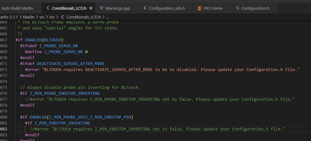
You need to set Z_MIN_PROBE_ENDSTOP_INVERTING to "true" but then the error will not allow to upload cause of an error telling you to set it to false.
Same goes for Z_MIN_ENDSTOP_INVERTING.
In the Conditionals_LCD.h you can change this commend into // in front of the error rule (see attached file), then it will allow to upload and now my printer is fully functional including all options like safe homing etc.
I will make a thread on github later with complete explainations of my printer, also where i explain the 3 weeks of searching how to get my firmware to the latest marlin (2.1.1.)
Good luck to all if you're stuck on this item.
Greeting, Sander
I have a custom build based on the Velleman K8200 but enlarged and use a K8400 mainbord.
But 3DRAG (Velleman is a clone) boards work the other way around.
You need to set Z_MIN_PROBE_ENDSTOP_INVERTING to "true" but then the error will not allow to upload cause of an error telling you to set it to false.
Same goes for Z_MIN_ENDSTOP_INVERTING.
In the Conditionals_LCD.h you can change this commend into // in front of the error rule (see attached file), then it will allow to upload and now my printer is fully functional including all options like safe homing etc.
I will make a thread on github later with complete explainations of my printer, also where i explain the 3 weeks of searching how to get my firmware to the latest marlin (2.1.1.)
Good luck to all if you're stuck on this item.
Greeting, Sander
Sorry, only registered users may post in this forum.