MKS Monster8
Posted by mga
|
Re: MKS Monster8 June 29, 2022 07:13PM |
Registered: 7 years ago Posts: 341 |
Fantastic!
You can ignore all the warnings with the exception of "Motherboard DIAG jumpers must be removed when SENSORLESS_HOMING is disabled." These jumpers connect the diag pins of the TMC2209s to the endstops. They should be removed.
"I have two z motors and two z endstops" - both Z motors should be turning now. If they just buzz that means they're fighting each other and need to turn in opposite directions. To fix that enable #define INVERT_Z2_VS_Z_DIR in configuration_adv.h.
My understanding is you have 6 endstop connectors. Here's my understanding of how you intend to use them:
BLTouch wiring is the same as 3dTouch wiring. See my June 16, 2022 12:48AM post for a wiring diagram.
You can ignore all the warnings with the exception of "Motherboard DIAG jumpers must be removed when SENSORLESS_HOMING is disabled." These jumpers connect the diag pins of the TMC2209s to the endstops. They should be removed.
"I have two z motors and two z endstops" - both Z motors should be turning now. If they just buzz that means they're fighting each other and need to turn in opposite directions. To fix that enable #define INVERT_Z2_VS_Z_DIR in configuration_adv.h.
My understanding is you have 6 endstop connectors. Here's my understanding of how you intend to use them:
- X_MIN - tied to X_MIN endstop
- X_MAX - not used - good candidate for filament detector
- Y_MIN - tied to Y_MIN endstop
- Y_MAX - tied to Z2_MAX endstop
- Z_MIN - tied to BLTouch
- Z_MAX - tied to Z_MAX endstop
BLTouch wiring is the same as 3dTouch wiring. See my June 16, 2022 12:48AM post for a wiring diagram.
|
Re: MKS Monster8 June 30, 2022 10:37AM |
Registered: 7 years ago Posts: 256 |
now I have settled the question of how to generate the firmware. Works.
I installed the one created by myself. The display works. Hotend heats up, fans are running. The engines ... nobody moves. The endstops are very strange ... I tried to press the endstop in y and the one of z1 would light up ... then after a while it stopped doing this. Such a thing had never happened to me. Now, when they are pressed, they work correctly: the LED lights up if I press them. But the engines don't work. Nobody moves. I have to think that there are no correct links.
I installed the one created by myself. The display works. Hotend heats up, fans are running. The engines ... nobody moves. The endstops are very strange ... I tried to press the endstop in y and the one of z1 would light up ... then after a while it stopped doing this. Such a thing had never happened to me. Now, when they are pressed, they work correctly: the LED lights up if I press them. But the engines don't work. Nobody moves. I have to think that there are no correct links.
|
Re: MKS Monster8 June 30, 2022 11:39AM |
Registered: 7 years ago Posts: 341 |
More good news!
None of the stepper motors turn? Not even the extruder? OUCH!
Yes, check the jumpers under the stepper drivers. I would expect to see "TMC CONNECTION ERROR" on the LCD if they were setup wrong.
Do the stepper motors make any noise?
How hard are the stepper motors to turn by hand after trying to move compared to right after a reset? If not enough power is being applied to move the stepper there still should be an obvious increase in how hard it is to turn by hand.
|
Re: MKS Monster8 July 01, 2022 03:30AM |
Registered: 7 years ago Posts: 256 |
if I turn on the machine I move the axes manually as if nothing had happened - the same way I can move them when it is not powered.
When the machine is turned on, the question marks appear on the axes because homing has not been done.
the stepper motors make no noise
the connected jumper is only the second one starting from the left, as indicated in the manual for TMC2209.
Did I put jumpers only where there is a driver ... or do I put them all over the place even if it's empty?
|
Re: MKS Monster8 July 01, 2022 07:33AM |
Registered: 7 years ago Posts: 341 |
The steppers will be powered only a few minutes after being commanded to move. Try commanding a move and then turning it by hand.
The jumpers in the empty spaces don't matter.
Do you have access to a voltmeter? If yes measure the voltage at the corner pins on one of the stepper drivers. One should measure 12V (or 24V if you have a 24V system).
The jumpers in the empty spaces don't matter.
Do you have access to a voltmeter? If yes measure the voltage at the corner pins on one of the stepper drivers. One should measure 12V (or 24V if you have a 24V system).
|
Re: MKS Monster8 July 02, 2022 01:02AM |
Registered: 7 years ago Posts: 341 |
Apparently there are different flavors of TMC2209 stpper driver modules.
The Monster8 is setup to have it on pin 13.
If this is the issue then your LCD should say "TMC CONNECTION ERROR". If it just says "Ready" then you are talking to all the TMC2209s and we need to look some place else.
If you have "TMC CONNECTION ERROR" then I'll want to know the manufacturer of the modules and I'll want VERY good pictures of the top and bottom of the modules.
- Some can be set so the UART signal is on pin 12 or pin 13.
- Some can be set so the UART signal is on pin 11 or pin 12.
The Monster8 is setup to have it on pin 13.
If this is the issue then your LCD should say "TMC CONNECTION ERROR". If it just says "Ready" then you are talking to all the TMC2209s and we need to look some place else.
If you have "TMC CONNECTION ERROR" then I'll want to know the manufacturer of the modules and I'll want VERY good pictures of the top and bottom of the modules.
|
Re: MKS Monster8 July 02, 2022 05:36AM |
Registered: 7 years ago Posts: 256 |
I checked the current. 12 volts arrive on the drivers.
The motors make no noise.
The panel does not report errors to me.
I can think of a connection error on the steppers.
Maybe the endstops ...?
Following your advice the steppers are connected by skipping a position by viad of Z1 and Z2.
Suppose it got confused, maybe it crashes.
Then the drivers are positioned like this:
Driver1 X
Driver2 Y
Driver3 Z1
Driver4 Z2
Driver5 Extruder
endstop
X-
Y-
Z- (Z1)
Y + (Z2)
initially the drivers I had arranged them differently, but on the card it is expressly indicated Z1 and Z2.
However it doesn't work even when I change the layout.
Maybe the cables on the steppers? But if they are wrong, shouldn't they be buzzing?
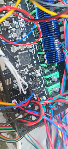
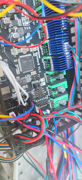
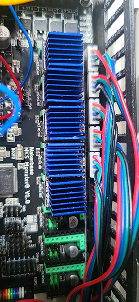
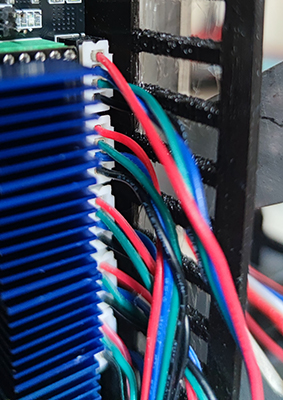
in the photos I show you how the cables were arranged with the modification Z1 and Z2. I also tried putting the driver in position 5 for safety ... but nothing.
I am quite convinced that this is a foolish mistake of mine.
The motors make no noise.
The panel does not report errors to me.
I can think of a connection error on the steppers.
Maybe the endstops ...?
Following your advice the steppers are connected by skipping a position by viad of Z1 and Z2.
Suppose it got confused, maybe it crashes.
Then the drivers are positioned like this:
Driver1 X
Driver2 Y
Driver3 Z1
Driver4 Z2
Driver5 Extruder
endstop
X-
Y-
Z- (Z1)
Y + (Z2)
initially the drivers I had arranged them differently, but on the card it is expressly indicated Z1 and Z2.
However it doesn't work even when I change the layout.
Maybe the cables on the steppers? But if they are wrong, shouldn't they be buzzing?
in the photos I show you how the cables were arranged with the modification Z1 and Z2. I also tried putting the driver in position 5 for safety ... but nothing.
I am quite convinced that this is a foolish mistake of mine.
|
Re: MKS Monster8 July 02, 2022 09:03AM |
Registered: 7 years ago Posts: 341 |
|
Re: MKS Monster8 July 02, 2022 09:55AM |
Registered: 7 years ago Posts: 256 |
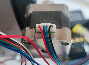
I do not understand what you are saying now. One way or another I will find how to connect the motors. I can show you the photo of how the colors go on the steppers and drivers.
red green blue black and on the engine become red blue green black.
Only green and blue or black and red are inverted if I have to consider the front view with respect to the stepper motor.
it seems to me that they should be considered in alternating pairs.
red green blue black and on the engine become red blue green black.
Only green and blue or black and red are inverted if I have to consider the front view with respect to the stepper motor.
it seems to me that they should be considered in alternating pairs.
|
Re: MKS Monster8 July 02, 2022 02:37PM |
Registered: 7 years ago Posts: 341 |
I can see why SOME of the stepper motors don't rotate.
Your stepper motors consist of two coils. Red and blue wires go to one coil and the other coil has green and black. Pins 1 & 2 on the connector go to one coil. Pins 3 & 4 go to the other coil.
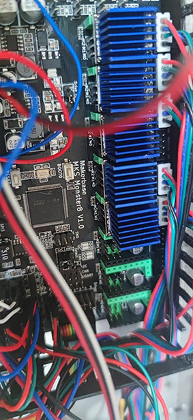
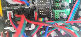
In one of your snapshots I see:
X : red, blue, green, black - should work
Y : red, green, blue, black - should NOT work
Z1: red, green, blue, black - should NOT work
E : red, green, blue, black - should NOT work
Z2: red, green, blue, black - should NOT work
I suggest changing your connectors so they are all the same as the X axis.
Don't get confused about all the different options for wiring the steppers. There's lots of ways of wiring the connectors. Some work, some don't. Of the ones that work, some result in rotation in one direction, the others rotation in the opposite direction. I can go into details if wanted.
Your stepper motors consist of two coils. Red and blue wires go to one coil and the other coil has green and black. Pins 1 & 2 on the connector go to one coil. Pins 3 & 4 go to the other coil.
In one of your snapshots I see:
X : red, blue, green, black - should work
Y : red, green, blue, black - should NOT work
Z1: red, green, blue, black - should NOT work
E : red, green, blue, black - should NOT work
Z2: red, green, blue, black - should NOT work
I suggest changing your connectors so they are all the same as the X axis.
Don't get confused about all the different options for wiring the steppers. There's lots of ways of wiring the connectors. Some work, some don't. Of the ones that work, some result in rotation in one direction, the others rotation in the opposite direction. I can go into details if wanted.
|
Re: MKS Monster8 July 04, 2022 03:14AM |
Registered: 7 years ago Posts: 256 |
|
Re: MKS Monster8 July 04, 2022 04:06AM |
Registered: 7 years ago Posts: 256 |
on the driver putting black, green, red, blue does not work. But do I have to change them all every time or can I try just one?
I have always changed them all (except the previous mistake)
At this point it looks like a random draw even though it can't.
on the stepper I have red, blue, green, black and the pairs are red, green - blue, black. I have tried with the tester and I am sure of the pairs.
Edited 1 time(s). Last edit at 07/04/2022 04:07AM by mga.
|
Re: MKS Monster8 July 04, 2022 07:45AM |
Registered: 7 years ago Posts: 256 |
|
Re: MKS Monster8 July 04, 2022 08:30AM |
Admin Registered: 13 years ago Posts: 6,998 |
use a multi meter to find the stepper motor coil pairs
all 3d printer motherboard stepper driver connectors are pins 1 and 2 are 1 coil, pins 3 and 4 are the second coil.
See [reprap.org] for details and other methods to find the coils
all 3d printer motherboard stepper driver connectors are pins 1 and 2 are 1 coil, pins 3 and 4 are the second coil.
See [reprap.org] for details and other methods to find the coils
|
Re: MKS Monster8 July 04, 2022 10:50AM |
Registered: 7 years ago Posts: 341 |
Using a tester you determined that:
That means one pair is red & green and the other pair is blue & black.
At the controller the connector should be:
Was there a combination where the motor(s) made noise?
- There is continuinty between red & green.
- There is continuiity between blue & black.
- There is NOT continuity between red and blue.
- There is NOT continuity between green and black.
That means one pair is red & green and the other pair is blue & black.
At the controller the connector should be:
- Pin 1 - red
- Pin 2 - green
- Pin 3 - blue
- Pin 4 - black
Was there a combination where the motor(s) made noise?
|
Re: MKS Monster8 July 05, 2022 03:37AM |
Registered: 7 years ago Posts: 256 |
cable connection is just as you describe. Let us now assume that it is correct. I think that's right. The steppers make no noise. I have to move the problem. As far as I know if the printer does not perform homing it cannot move the axes because it has no Cartesian references.
An item appears in the menu: Auto home. If I press nothing happens.
Maybe the logic of the endstops? Maybe they inhibit movement?
I am attaching the parameters that I have now.
I don't understand for example how to say that Z2 has YMax endstop. I think there is some kind of routine that does this automatically, but I'm not sure, also because I also have a bltouch type sensor.
By the way BLTouch seems to work because if I turn on the printer it cycles by activating the sensor a few times.
Edited 1 time(s). Last edit at 07/05/2022 04:18AM by mga.
|
Re: MKS Monster8 July 05, 2022 10:10AM |
Registered: 7 years ago Posts: 341 |
The line #define Z2_USE_ENDSTOP _YMAX_ in configuration_adv.h does this.Quote
how to say that Z2 has YMax endstop
I believe the BLTouch will cycle a few times automatically when power is applied. There should be a LCD menu that allows you to deploy & stow the probe manually.
Even if the endstop logic is wrong, with the current settings there should be movement in at least one direction.
If you heat the extruder, does the E motor turn when commanded?
What I don't understand is how the motors continue to turn freely by hand after being commanded to move. If they are getting power and the coils are wired correctly there should be a very obvious increase in the resistance to turning by hand (at least until the motors time out after 2 minutes).
Let's try two things:
- Increase motor current from 800 mA to 1200 mA
- Enable MONITOR_DRIVER_STATUS and disable STOP_ON_ERROR.
|
Re: MKS Monster8 July 08, 2022 03:54AM |
Registered: 7 years ago Posts: 256 |
I did a M122 test. The motors do not move even in jog. Then I do it again by changing the microsteps.
INVIATI: M122
LETTI: X Y Z Z2 E
LETTI: Address 0 0 0 0 0
LETTI: Enabled false false false false false
LETTI: Set current 800 800 800 800 800
LETTI: RMS current 795 795 795 795 795
LETTI: MAX current 1121 1121 1121 1121 1121
LETTI: Run current 25/31 25/31 25/31 25/31 25/31
LETTI: Hold current 12/31 12/31 12/31 12/31 12/31
LETTI: CS actual 12/31 12/31 12/31 12/31 12/31
LETTI: PWM scale
LETTI: vsense 1=.18 1=.18 1=.18 1=.18 1=.18
LETTI: stealthChop true true true true true
LETTI: msteps 16 16 16 16 16
LETTI: interp true true true true true
LETTI: tstep max max max max max
LETTI: PWM thresh.
LETTI: [mm/s]
LETTI: OT prewarn false false false false false
LETTI: pwm scale sum 14 14 14 14 14
LETTI: pwm scale auto 0 0 0 0 0
LETTI: pwm offset auto 36 36 36 36 36
LETTI: pwm grad auto 14 14 14 14 14
LETTI: off time 0 0 0 0 0
LETTI: blank time 24 24 24 24 24
LETTI: hysteresis
LETTI: -end -1 -1 -1 -1 -1
LETTI: -start 1 1 1 1 1
LETTI: Stallguard thrs 0 0 0 0 0
LETTI: uStep count 8 8 776 776 1000
LETTI: DRVSTATUS X Y Z Z2 E
LETTI: sg_result 0 0 0 0 0
LETTI: stst
LETTI: olb
LETTI: ola
LETTI: s2gb
LETTI: s2ga
LETTI: otpw
LETTI: ot
LETTI: 157C
LETTI: 150C
LETTI: 143C
LETTI: 120C
LETTI: s2vsa
LETTI: s2vsb
LETTI: Driver registers:
LETTI: X 0xC0:0C:00:00
LETTI: Y 0xC0:0C:00:00
LETTI: Z 0xC0:0C:00:00
LETTI: Z2 0xC0:0C:00:00
LETTI: E 0xC0:0C:00:00
LETTI:
LETTI:
LETTI: Testing X connection... OK
LETTI: Testing Y connection... OK
LETTI: Testing Z connection... OK
LETTI: Testing Z2 connection... OK
LETTI: Testing E connection... OK
LETTI: ok
Edited 1 time(s). Last edit at 07/08/2022 05:55AM by mga.
|
Re: MKS Monster8 July 08, 2022 05:53AM |
Registered: 7 years ago Posts: 256 |
I found.
Before changing the current I wanted to see if from this M122 screen you can tell if something is wrong.
INVIATI: M122
LETTI: X Y Z Z2 E
LETTI: Address 0 0 0 0 0
LETTI: Enabled false false false false false
LETTI: Set current 800 800 800 800 800
LETTI: RMS current 795 795 795 795 795
LETTI: MAX current 1121 1121 1121 1121 1121
LETTI: Run current 25/31 25/31 25/31 25/31 25/31
LETTI: Hold current 12/31 12/31 12/31 12/31 12/31
LETTI: CS actual 12/31 12/31 12/31 12/31 12/31
LETTI: PWM scale
LETTI: vsense 1=.18 1=.18 1=.18 1=.18 1=.18
LETTI: stealthChop true true true true true
LETTI: msteps 64 64 64 64 64
LETTI: interp true true true true true
LETTI: tstep max max max max max
LETTI: PWM thresh.
LETTI: [mm/s]
LETTI: OT prewarn false false false false false
LETTI: triggered
LETTI: OTP false false false false false
LETTI: pwm scale sum 14 14 14 14 14
LETTI: pwm scale auto 0 0 0 0 0
LETTI: pwm offset auto 36 36 36 36 36
LETTI: pwm grad auto 14 14 14 14 14
LETTI: off time 3 0 0 0 0
LETTI: blank time 24 24 24 24 24
LETTI: hysteresis
LETTI: -end -1 -1 -1 -1 -1
INVIATI: M105
LETTI: -start 1 1 1 1 1
LETTI: Stallguard thrs 0 0 0 0 0
LETTI: uStep count 898 2 2 2 1022
LETTI: DRVSTATUS X Y Z Z2 E
LETTI: sg_result 0 0 0 0 0
LETTI: stst
LETTI: olb
LETTI: ola
LETTI: s2gb
LETTI: s2ga
LETTI: otpw
LETTI: ot
LETTI: 157C
LETTI: 150C
LETTI: 143C
LETTI: 120C
LETTI: s2vsa
LETTI: s2vsb
LETTI: Driver registers:
LETTI: X 0xC0:0C:00:00
LETTI: Y 0xC0:0C:00:00
LETTI: Z 0xC0:0C:00:00
LETTI: Z2 0xC0:0C:00:00
LETTI: E 0xC0:0C:00:00
LETTI:
LETTI:
LETTI: Testing X connection... OK
LETTI: Testing Y connection... OK
LETTI: Testing Z connection... OK
LETTI: Testing Z2 connection... OK
LETTI: Testing E connection... OK
LETTI: ok
LETTI: ok T:26.04 /0.00 @:0
INVIATI: M105
LETTI: ok T:26.20 /0.00 @:0
|
Re: MKS Monster8 July 08, 2022 05:56AM |
Registered: 7 years ago Posts: 341 |
Proof that we're talking to the TMC2209s. Great news.
Please verify again that the motors turn freely by hand after sending motor movement commands. They should remain powered up for 2 minutes after the command and should be hard to turn by hand.
If they turn freely by hand after being commanded to move then we're not sending them power. I can't think of why that would be the case.
If they are hard to turn by hand then I can think of the following reasons for no movement:
- Not enough current. Try changing all five mootors from 800mA to 1200mA.
- Too much acceleration. Drop that by a factor of 10.
- Too high a speed. Drop the max by a factor of 10.
|
Re: MKS Monster8 July 08, 2022 09:51AM |
Registered: 7 years ago Posts: 256 |
|
Re: MKS Monster8 July 08, 2022 11:46AM |
Registered: 7 years ago Posts: 341 |
Something didn't go right if you changed the current to 1200 and it is still reporting 800. Try compiling and downloading again.
The other thing is the current setting may be stored in EEPROM. Did you do a M502 followed by a M500? That will guarantee any new settings are being used.
Let's test the endstop theory. Do a M119. None of them should say triggered. Do a M121 to disable endstops and try to move the motors.
The other thing is the current setting may be stored in EEPROM. Did you do a M502 followed by a M500? That will guarantee any new settings are being used.
Let's test the endstop theory. Do a M119. None of them should say triggered. Do a M121 to disable endstops and try to move the motors.
|
Re: MKS Monster8 July 11, 2022 04:02AM |
Registered: 7 years ago Posts: 256 |
i made M119.
I have all the endstops open because I manually moved the axes in order not to have them in the closed state (also turning the worm screws in z). But the result is this:
x_min: TRIGGERED
y_min: TRIGGERED
z_min: TRIGGERED
z_max: open
z2_max: TRIGGERED
z_max is bltouch
the others are all wrong. I tried to rotate the endstop connection 180 °, but the result is the same.
If I invert the endstop logic to false it does not allow me to create the firmware because it creates a block due to bltouch. I don't know for what reason but it dictates that the logic is always "false", but if I do this, it doesn't recognize the setting.
__________________________________
buildroot/share/PlatformIO/scripts/../../../../Marlin/src/inc/Conditionals_LCD.h:1025:6: error: #error "BLTOUCH requires Z_MIN_PROBE_ENDSTOP_INVERTING set to false. Please update your Configuration.h file."
1025 | #error "BLTOUCH requires Z_MIN_PROBE_ENDSTOP_INVERTING set to false. Please update your Configuration.h file."
| ^~~~~
buildroot/share/PlatformIO/scripts/../../../../Marlin/src/inc/Conditionals_LCD.h:1030:8: error: #error "BLTOUCH requires Z_MIN_ENDSTOP_INVERTING set to false. Please update your Configuration.h file."
1030 | #error "BLTOUCH requires Z_MIN_ENDSTOP_INVERTING set to false. Please update your Configuration.h file."
__________________________________
well ... I understand that I should set on the firmware: bltouch is zmax and then make it clear that all the endstops are normally open and are closed when the x, y and z axis are at a minimum.
Another thing, with M121 nothing changes. No noise, no result, nothing moves.
|
Re: MKS Monster8 July 11, 2022 07:03AM |
Admin Registered: 13 years ago Posts: 6,998 |
|
Re: MKS Monster8 July 11, 2022 07:40AM |
Registered: 7 years ago Posts: 341 |
BLTouch is a special situation. Marlin knowns that it should be set to "false" and enforces that rule.
Please follow Dusts's advice on the endstops.
"with M121 nothing changes. No noise, no result, nothing moves." That means we have a system wide issue.
Perhaps we're only talking to one TMC2209. Try setting the current for each stepper to a unique value and then doing M122.
Another possibility is the fuse for the stepper power may be partially bad. Try replacing it.
Also, comment out (disable) EEPROM_SETTINGS. It's not needed at this stage and can cause confusion.
|
Re: MKS Monster8 July 11, 2022 04:20PM |
Registered: 7 years ago Posts: 341 |
|
Re: MKS Monster8 March 05, 2023 04:48AM |
Registered: 8 years ago Posts: 2 |

|
Re: MKS Monster8 March 05, 2023 11:47AM |
Registered: 7 years ago Posts: 341 |
Here's the pinout of your board.
Looks like you put the three pin connector from the BLTouch into the three pin 3D Touch connector on the motherboard.
The two pin connector goes into one of the endstops.
In the klipper config file go to the BLTOUCH section
Do a google search on klipper bltouch setup and you'll find lots of how to info.
---
Curiousity question - why are you posting a klipper question in a Marlin forum?
Looks like you put the three pin connector from the BLTouch into the three pin 3D Touch connector on the motherboard.
The two pin connector goes into one of the endstops.
In the klipper config file go to the BLTOUCH section
- Set sensor_pin: to ^PA13 or ^PA14 or ^PA15 or ^PB12 or ^PB13 as appropriate for the endstop being used.
- Set control_pin: to PA8.
Do a google search on klipper bltouch setup and you'll find lots of how to info.
---
Curiousity question - why are you posting a klipper question in a Marlin forum?
|
Re: MKS Monster8 March 07, 2023 08:44PM |
Registered: 8 years ago Posts: 2 |

Sorry, only registered users may post in this forum.