Motion unit development
Posted by atmark
|
Motion unit development October 13, 2019 05:40AM |
Registered: 8 years ago Posts: 96 |
This thread is split up from the main thread.
Down below you'll find previous discussions about the concept.
company website // portfolio // project gallery // instagram
Down below you'll find previous discussions about the concept.
Quote
atmark
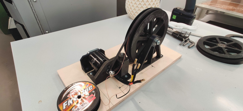
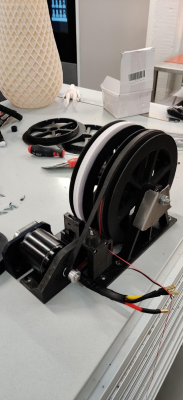
I'm currently designing a bracket for the HP4 bldc servo motor and the spool, and I wanted to share my tests so far.
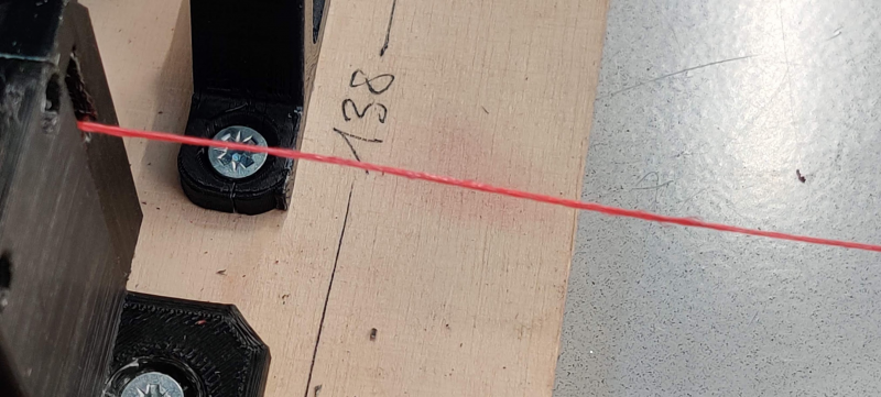
The bracket is meant for the ODrive D5065 motor. My goal is to design a single motion unit, that includes the motor, a belt tensioner and the spool system in one rigid frame, which I probably am going to lasercut out of sheet metal. For now, I'm still thinking about the spool system. If you look few posts back in this thread, there was a discussion about the constant radius of the spool and how to compensate the line build up. An idea I had, was to route the line in a small groove in the middle of the GT2 spool, in the way that the belt is pressing it against the spool as you can see in the last pic.
I just tried to block the spool from rotating and pulled the line as hard as I could and it didn't move at all
It's still too early to say this concept works, but it is a promising start. It might be, that constant line movement is going to bite into the belt and it fails that way. You'll never know. What I'll do next is rerouting the end of the line onto a second spool, which I most likely will attach onto the same spool axle. And that spool will rotate independently from the first one. I was also thinking to spring load it, so that the excess line is always spooled up as the line moves.
Quote
tobben
Cool!
Independent spool units are nice.
If you can place them at the anchors (instead of having all several spools at one anchor), you will get less line flex, since there will be less suspended line in the air.
Good idea to pinch the line under the belt.
That might actually work very well =D
You could pinch it for several rounds (along a helix groove), or just increase the spool radius, if one round of pinched line isn't enough.
It might be a challenge assure zero slippage over time, since both line and belt will change properties as they get old/worn down.
Some data on that would be super interesting, like accelerating a 5kg weight quickly up and down 1 m 10000 times or something.
Using high accelerations would be interesting because the belt will flex/contract a bit when tension changes, and I don't know how it will affect the line.
Hopefully very little.
Anyways, that might be a very nice upgrade of the spool system
Quote
atmark
Thanks!
I just put a heavy weight on the line and looked first if the line holds, and after I couldn't see any slipping, I bounced the whole system until the line snapped Video: testing slipping
No slipping what so ever
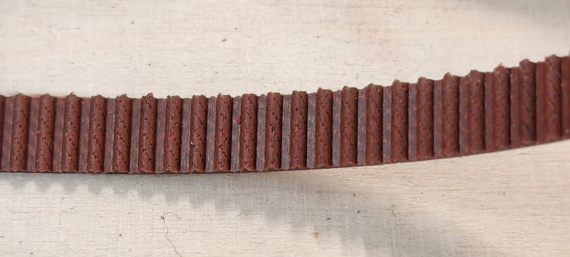
I believe the line should be able to handle 40 kg of drag, so friction-wise I can't see any issues. Obviously the long term failure rate is a question mark, but I think it might work quite well because the line isn't cutting radially into the belt. The only force is applied axially and the belt is pressed by the line by only 0,25 mm
Your idea of hooking some weight on the line and do some repetitive acceleration testing sounds very good! I'll try to set up the electronics next week. What values would you suggest for weight, speed and acceleration?
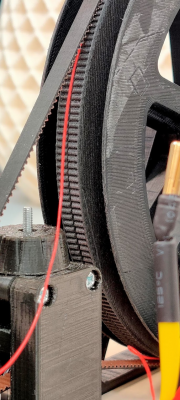
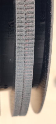
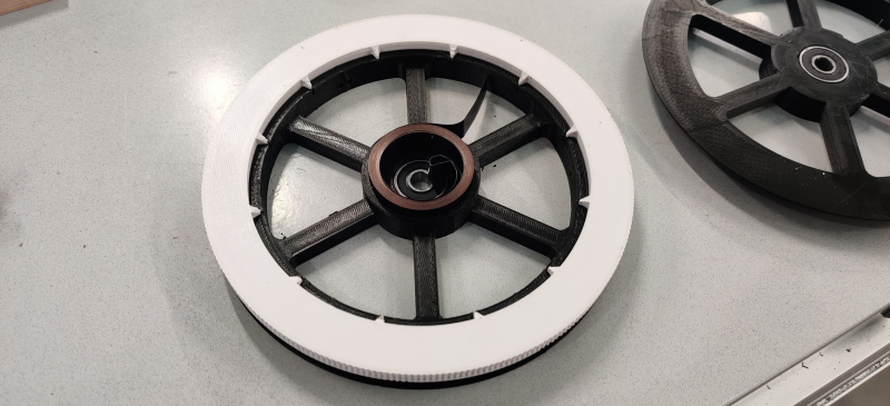
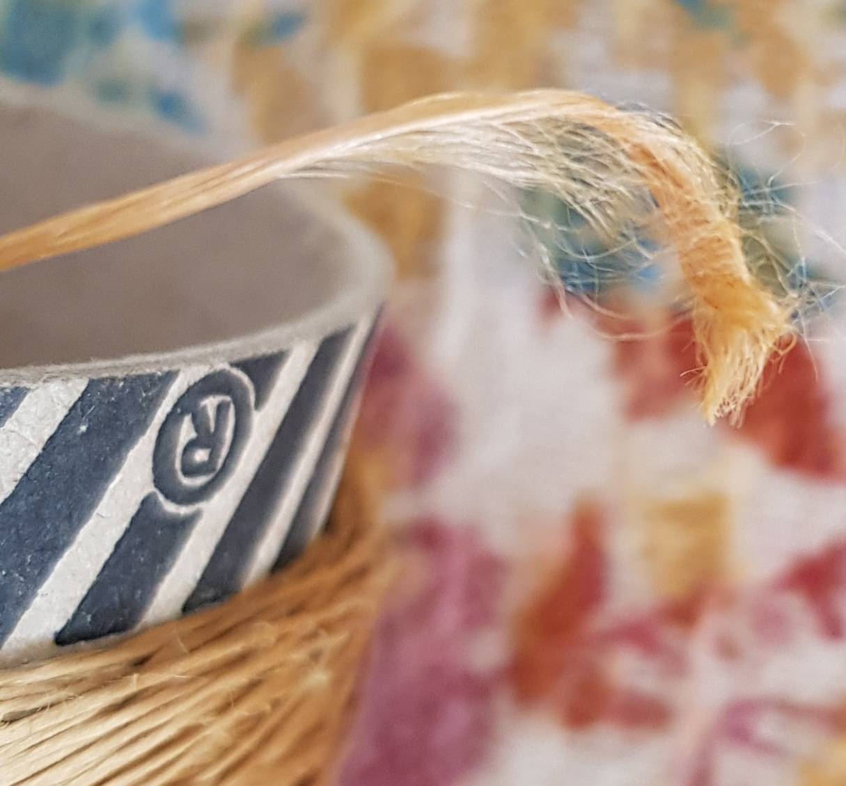
Here are also some close ups of the GT2 spool and the belt directly after the test. For the spool I used Octofiber PETG-CF.
Quote
tobben
Woah, that's even more friction than I imagined. Impressive!
CF enforced plastics have a quite rough surface.
Where did the line snap?
Was it the CF that wore down the line?
Since I would be aiming for HP usage, I'd test numbers relevant to the application first.
I'd use ca 50% more weight, speed and acceleration than my HP4 prototype is experiencing.
So ca 5 kg of weight, accelerate 15 m/s² , up to 1 m/s. Use a distance of 1 m up and down, say 10k times.
That's a 3h test. You could go crazy and just let it run all night if you're feeling confident
It would also be interesting to know if the mechanism works with pure PLA.
A spool out of PLA printed hot (say 240 C) would give much less friction than the PLA-CF in your prototype, I guess.
It would be interesting to know if it would still be enough, or if the CF is required.
Images like the one you showed would be a very interesting part of the result.
In particular, if the line does slip, I'm interested in how damaged the belt gets.
Also interesting to know if a slipping line cuts into the spool.
The mechanism is interesting in it's own right, so if the HP4 application proves to be well within limits of the mechanism, I would have done additional tests.
Like, measuring a slowly applied force up until the line breaks or starts slipping, or until the plastic spool breaks.
(Film a weight that is hooked onto a one end of a line, and pulled. Could capture both force and amount of slip/flex in one shot.)
Abruptly applied force is also interesting (requires a high-speed camera, or a weight that can store a max value).
Quote
atmark
Yeah, I was quite amazed too to be honest.
The line snapped 5 mm before the knot I made to hold the weight. So the CF spool didn't have any effect on the snapping. I'm aware of the abrasive nature of CF, so it's not said that it could not happen, but in this case it didn't. I can print a new spool out of PLA, no problem. It will be interesting to test it.
Let's see how I can setup a test rig. The motion repetition won't be a big issue once I get to setup the ODrive board and Duet. Is the firmware easy to install? Then, I assume a simple gcode does the magic?
Btw, I wrote you yesterday a mail, but it's still in my to be sent folder (I forgot that the schools network is down for maintanance for couple of days) anyway, I wrote that I ordered braided PE fishing line that is two-colored (yellow/black), so it has a repetitive weave pattern, which could be used for line length readout with a IR sensor, as black plastic does not reflect IR light very well. That's why the material of black plastic can't be identified in automated recycling. Different plastics reflect IR light differently.
So, additionally to the mechanics I was thinking about position feedback via sensor readout. Whats your opinion on that? There was also some discussion about measuring the line tension. Could that be useful to integrate in the motion system? At school we have a quite big range of sensors and other electronic equipment for prototyping. You can check technIcal details at Seeedstudio Grove
You can hook these sensors very easy to arduino, rasbi, etc.
Quote
tobben
Yes, the firmware should be straight forward to install. Just use the Duet2CombinedFirmware.bin you find in the repo (https://gitlab.com/tobben/hangprinter/tree/version_4_dev/firmware/RepRapFirmware), and follow standard Duet installation procedure. Gcode should to the magic, yesBe aware that your ODrive configuration will affect the movements. Max acceleration, max speed, step size etc needs to be configured correctly in the ODrive firmware. There's an example that matches my specific motors here: [gitlab.com] Follow the official ODrive documentation to find numbers that match your motors.
If the fishing line has any flex at all, this will affect the readings. So if the line (and hence the pattern) is stretched out, you might wind in 10.1 mm when you thought you did only 10.0.
On the other hand, since you're detecting the pattern, you'll know when you have unwound the same segment of fishing line, regardless of how stretched it was when wound and unwound.
This makes the system immune to a family of errors where flex is "stored" on the spool when wound in under heavy load.
The line will always be twisted though. How would the system cope with that?
And how would it behave if the line got very slack? Could we route the line through a very thin transparent tube, to keep it from kinking under the sensor?
For such a sensor to be useful, it would need to be very fool proof since so many weird things can happen during a print.
company website // portfolio // project gallery // instagram
|
Re: Motion unit development October 13, 2019 05:58AM |
Registered: 8 years ago Posts: 96 |
Quote
tobben
If the fishing line has any flex at all, this will affect the readings. So if the line (and hence the pattern) is stretched out, you might wind in 10.1 mm when you thought you did only 10.0.
On the other hand, since you're detecting the pattern, you'll know when you have unwound the same segment of fishing line, regardless of how stretched it was when wound and unwound.
This makes the system immune to a family of errors where flex is "stored" on the spool when wound in under heavy load.
Hmm, ok let's assume the line flexes and instead of being 10 mm it is 10.1 mm.
The sensor reads the line pattern like a binary code yellow->black->yellow->black etc. It doesn't know how long the physical distance between the pattern is and it shouldn't matter since the line flexes.
What it can read, is the time passed between the patterns. Maybe this signal could be used for synchronizing the spool driving motors?
If the motor executes, let's say, 100 steps and the sensors read during this time 10 sequences, we assume that there is no flex, no slippage
But, if the sensor readout is only 9, then there is a fault. And obviously also when the readout is 11.
When the reading is 9, then not enough sequences passed the sensor, because the line got stretched?
And in the opposite when being 11, too many sequences passed, because the line slipped?
I'm not sure if the logic is correct, what do you think?
|
Re: Motion unit development October 13, 2019 06:13AM |
Registered: 8 years ago Posts: 96 |
Quote
tobben
The line will always be twisted though. How would the system cope with that?
And how would it behave if the line got very slack? Could we route the line through a very thin transparent tube, to keep it from kinking under the sensor?
For such a sensor to be useful, it would need to be very fool proof since so many weird things can happen during a print.
That are very good questions! I haven't yet an answer to the twisting. It might be something that is not possible to prevent.
The idea of having a small tube is a good one! It could be a piece of clear acrylic. Then you could punch a small hole into in with a hot needle, or you could laser drill it. This way the hole surface remains clear. If you drill it mechanically, it gets dull.
Maybe the acrylic piece could be square, so you could have two sensors perpendicular to each other on two sides of it. And when the line twists you would do a comparison of the two readings to decide which reflection is "stronger"? I'm not sure if this is logical either

Here are the two lines I ordered. I think the second one is the most suitable.
Patterned fishing line 1
Patterned fishing line 2
|
Re: Motion unit development October 13, 2019 08:00AM |
Registered: 8 years ago Posts: 96 |
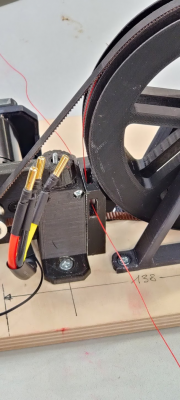
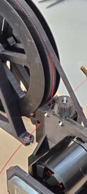
Ok, here are some pics and vids of todays testing.
I found two identical steel pieces, each way over 4 kg (the gauge maxed out). They might weight around 5 kg.
So, I put first one to each end of the line to have a counter balance. Then I attached a power drill to the motor axle and spun it a little. That went well.
After that, I replaced one of the weights with a set of allen keys, just enough to keep the line tense. On the other end I had the 4-5 kg tool. Again power drill to axle and some round back and forth.
This time the line slipped after a while. I noticed, that the line got squished by the v-groove bearings. That might changed the line profile enough to slip under the belt. After applying more tension on the belt it worked again.
During and after testing I couldn't see any damage to the belt, but the line got sheared a bit. Most likely by the GF spool. I'm printing a PLA version now, let's see how that performs.
Video: Test rig with line deflectors
Video: Test rig including weight and counter balance
Video: Moving belt under load
Video: Turning the spool with counter balanced line
Video: Over 4 kg of mass hanging on the line
The rattling noice in the last video comes from the slipping power drill
|
Re: Motion unit development October 13, 2019 09:02AM |
Moderator Registered: 10 years ago Posts: 401 |
Cool! Interesting to see how it behaves.
Both the max load and the min load will be challenges I guess.
A lot of the time, motors will have to wind in line with very very little counter weight.
Brand new FireLine behaves almost like steel wire, and then it becomes soft like silk after only a little usage.
I hope the pinch system will work with even the softest of line.
However, since we won't have any line buildup, we could go for thicker lines, like up to 1mm or even thicker.
I looked closer at the fishing lines you had ordered. They are braided, and very thin, so they will flex quite a bit. At least enough to be a problem while Hangprinting.
torbjornludvigsen.com
|
Re: Motion unit development October 13, 2019 12:08PM |
Registered: 8 years ago Posts: 96 |
What would be the ideal line in your opinion?
I was thinking of carbon fiber yarn. I actually bought some a while ago. Plain yarn with 2 or 3k fibers.
It truly is extremely strong, but it wears fast in its natural form. One option would be to soak it in polyurethane and let it cure. This way the fibers would stay neatly bundled, but it would also have a strong and flexible shell. Its not impossible to make, but involves lot of hassle. I'd prefer a off the shelf solution.
Steel wires will flex around 2-3%, so they aren't probably a way to go.
|
Re: Motion unit development October 13, 2019 12:55PM |
Registered: 5 years ago Posts: 155 |
|
Re: Motion unit development October 13, 2019 01:00PM |
Admin Registered: 16 years ago Posts: 13,886 |
... you can try with "high elastic" steel wires -- have some with outer diameters from 0,3mm upwards ...
Viktor
--------
Aufruf zum Projekt "Müll-freie Meere" - [reprap.org] -- Deutsche Facebook-Gruppe - [www.facebook.com]
Call for the project "garbage-free seas" - [reprap.org]
Viktor
--------
Aufruf zum Projekt "Müll-freie Meere" - [reprap.org] -- Deutsche Facebook-Gruppe - [www.facebook.com]
Call for the project "garbage-free seas" - [reprap.org]
|
Re: Motion unit development October 13, 2019 02:08PM |
Registered: 5 years ago Posts: 155 |
Another interesting material is yarn from PBO Zylon.
Longitudinal tensile Modulus:
Spectra: 66...124
Kevlar 49: 154
Steel: 210
PBO Zylon AS: 180
PBO Zylon HM: 270 GPa
Zylon is from a japanese manufacturer.
There is an even higher material called PBT = Poly(p-phenylene-2,6-benzobisthiazole) with modulus 320 GPa, but I didn't find wire/yarn for it.
Edited 1 time(s). Last edit at 10/13/2019 02:11PM by JoergS5.
|
Re: Motion unit development October 13, 2019 11:19PM |
Registered: 8 years ago Posts: 96 |
|
Re: Motion unit development October 14, 2019 01:06AM |
Registered: 8 years ago Posts: 96 |
Quote
JoergS5
Another interesting material is yarn from PBO Zylon
Yes, this is also interesting. Quick googling brought up a japanese fishing line manufacturer called Yotsumi. They have a Zylon base product line called YGK. Its a 5 m long line so it would about a suitable length. But its really expensive. 20-25€/5m :O
|
Re: Motion unit development October 14, 2019 02:53AM |
Registered: 5 years ago Posts: 155 |
Quote
atmark
Quote
JoergS5
Another interesting material is yarn from PBO Zylon
Yes, this is also interesting. Quick googling brought up a japanese fishing line manufacturer called Yotsumi. They have a Zylon base product line called YGK. Its a 5 m long line so it would about a suitable length. But its really expensive. 20-25€/5m :O
This here is cheaper: [www.ebay.com] but I didn't find the info which of the 2 types it is, you will have to ask the seller if you're interested buying.
More info about Zylon: [www.fiber-line.com]
Denier = Fadenstärke = thread strength
Edited 4 time(s). Last edit at 10/14/2019 04:10AM by JoergS5.
|
Re: Motion unit development October 14, 2019 02:59AM |
Admin Registered: 16 years ago Posts: 13,886 |
Quote
atmark
Quote
VDX
... you can try with "high elastic" steel wires -- have some with outer diameters from 0,3mm upwards ...
That's interesting. Seems to be a kind of spring steel? Do you have a supplier and/or some material specs for me?
... the "sourcing" was some +25 years ago, so no list of the suppliers around -- but you can search for "bowden steel wire" or steel wire in general, as I did then.
Here some of the remnants with two named types (the 0,3mm wire is on the spool -- the others were from 0,5mm to 2mm in diameter):

Viktor
--------
Aufruf zum Projekt "Müll-freie Meere" - [reprap.org] -- Deutsche Facebook-Gruppe - [www.facebook.com]
Call for the project "garbage-free seas" - [reprap.org]
|
Re: Motion unit development October 15, 2019 08:09AM |
Registered: 5 years ago Posts: 155 |
|
Re: Motion unit development October 15, 2019 10:07AM |
Registered: 8 years ago Posts: 96 |
Quote
JoergS5
@atmark
I bought the Zylon yarn now. If you have a test setup for me, I can measure the properties after receiving it.
Hey, that's cool!
I just need to build my test rig first. Also, I would need to know the yarn diameter once you can measure it.
For now, I can confirm that the GT2 spool made of PLA can't hold the line, it slips under the belt no matter how tense it is.
So, the surface roughness of the PETG-CF is crucial.
|
Re: Motion unit development October 15, 2019 02:30PM |
Registered: 5 years ago Posts: 155 |
Quote
atmark
...For now, I can confirm that the GT2 spool made of PLA can't hold the line, it slips under the belt no matter how tense it is.
So, the surface roughness of the PETG-CF is crucial.
If PETG-CF is so important for friction, you could print PLA in the inside and only the important outer surface with PETG.
One additional idea is the application of little industry diamonds on the surface. (a product in german: [prozesstechnik.industrie.de]) But it depends on the size of the diamonds whether you get more or less slippery. Little diamonds are used as lubricant also.
Edited 2 time(s). Last edit at 10/15/2019 02:43PM by JoergS5.
|
Re: Motion unit development October 16, 2019 09:05AM |
Registered: 8 years ago Posts: 96 |
@tobben
Ok, so far I was able to setup the rig, setup Duet and now I'm configuring ODrive.
I ran at this point into an issue while setting up the step_gpio_pin and dir_gpio_pin
Both will give me this error: "Attribute step/dir_gpio_pin not found"
Did you encounter something similar? Any advise before I dive into ODrive docs?
|
Re: Motion unit development October 17, 2019 03:31AM |
Registered: 5 years ago Posts: 155 |
There is a sample configuration for ODrive and Duet here under Config Comments: [hangprinter.org]
(blog by tobben)
(blog by tobben)
|
Re: Motion unit development October 17, 2019 11:04AM |
Registered: 8 years ago Posts: 96 |
Got it. I had a old firmware on my ODrive, after an update it worked and I also worked my way to the point that I can spin the motor!! Video: testing the motor
Next, I'm going to combine the motor bracket and the spool bracket into one single piece. I think it's bit easier to get the belt and the line deflectors aligned properly that way.
Btw, I've been thinking lately about a round timing belt instead of dyneema line or similar. That way we could be sure there won't be any slipping as the teeth would prevent it. There's no thing like round timing belt, but the next best thing that comes close to the idea is the ball chain on your basin plug.
Any thoughts on this?
Next, I'm going to combine the motor bracket and the spool bracket into one single piece. I think it's bit easier to get the belt and the line deflectors aligned properly that way.
Btw, I've been thinking lately about a round timing belt instead of dyneema line or similar. That way we could be sure there won't be any slipping as the teeth would prevent it. There's no thing like round timing belt, but the next best thing that comes close to the idea is the ball chain on your basin plug.

Any thoughts on this?
|
Re: Motion unit development October 18, 2019 02:30AM |
Registered: 5 years ago Posts: 155 |
|
Re: Motion unit development October 23, 2019 01:17AM |
Registered: 8 years ago Posts: 96 |
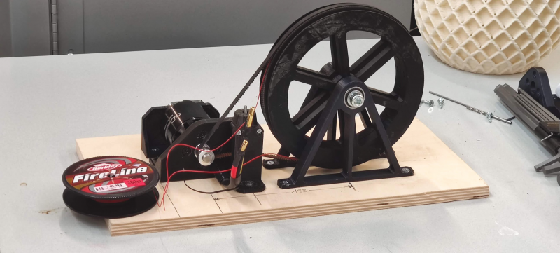
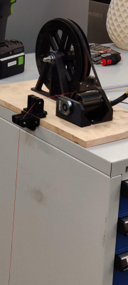
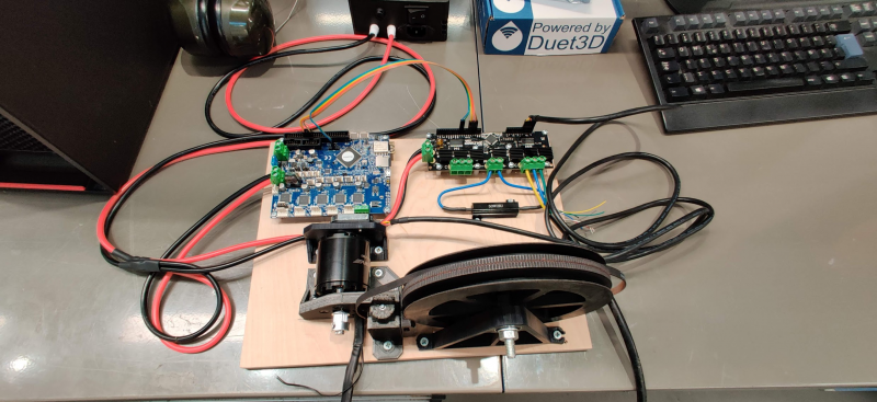
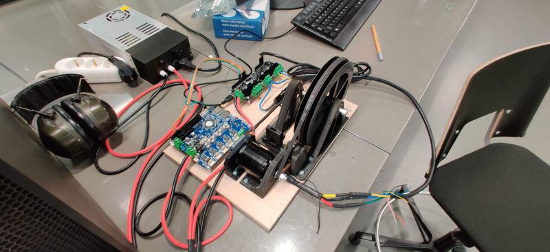
Update:
The rig is now ready. I made a secondary spool with a build in spiral spring. One end of the spring is fixed to the spool and the other end on the axle. The spring is pretensioned before the line is attached to the spool. That way it automatically winds in the line the first spool is feeding and vice versa. It works very nice, basically its the same wind in mechanism as in your vacuum cleaner.
I've also setup up the electronics and done some testing with weight on the line. First results are, that as I speed up the acceleration the line starts to slip. It might be necessary to have multiple windings on the first spool to buildup enough friction. But I noticed also that the GT2 spool's teeth profile wasn't that exact, so the belt didn't fit in perfectly all the way around. Gonna print another one with 0,1 mm layer height and slower print speed.

|
Re: Motion unit development October 24, 2019 07:00AM |
Registered: 5 years ago Posts: 155 |
|
Re: Motion unit development October 25, 2019 12:51PM |
Moderator Registered: 10 years ago Posts: 401 |
Very nice test rig! I love that spring loaded spool.
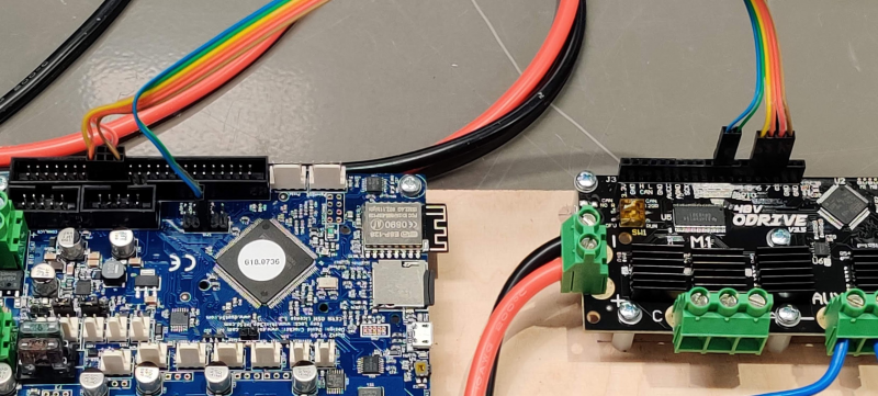
I see that you've got Duet<->ODrive UART plugged in.
I've done some work on that in the last few days (blog post coming I guess).
GPIO 5 on the ODrive is a tad noisy because of the circuit board design.
I used that pin for motor A/C direction signal, and started to notice a slight random-walk pattern on my prints.
Experiments showed that motor A and C accumulated an error of ca 1 degree per minute during print.
So now, I've moved motor A step to GPIO 1 and motor A dir to GPIO 2.
UART tx is moved to GPIO 3 and UART rx is moved to GPIO 4.
This fixed the issue.
To get the fix on your test rig (if you want/need it right away), you need to flash this firmware:
usart2 branch of ODrive repo
and set these pins on the ODrive:
torbjornludvigsen.com
I see that you've got Duet<->ODrive UART plugged in.
I've done some work on that in the last few days (blog post coming I guess).
GPIO 5 on the ODrive is a tad noisy because of the circuit board design.
I used that pin for motor A/C direction signal, and started to notice a slight random-walk pattern on my prints.
Experiments showed that motor A and C accumulated an error of ca 1 degree per minute during print.
So now, I've moved motor A step to GPIO 1 and motor A dir to GPIO 2.
UART tx is moved to GPIO 3 and UART rx is moved to GPIO 4.
This fixed the issue.
To get the fix on your test rig (if you want/need it right away), you need to flash this firmware:
usart2 branch of ODrive repo
and set these pins on the ODrive:
odrv0.axis0.config.step_gpio_pin = 1
odrv0.axis0.config.dir_gpio_pin = 2
torbjornludvigsen.com
|
Re: Motion unit development October 29, 2019 02:40PM |
Registered: 8 years ago Posts: 96 |
Thanks Tobben for the info! I will reflash my Odrive soon.
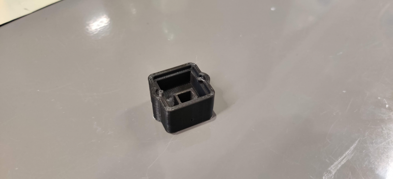
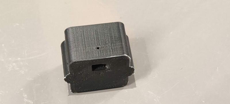
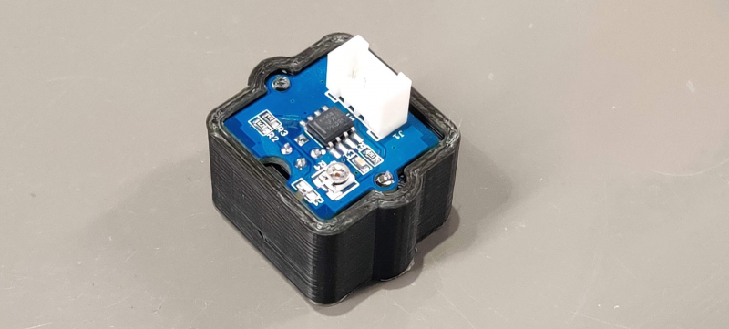
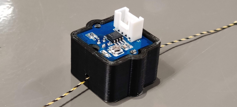
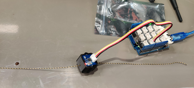
In the mean time I did some experiments with the black/yellow-striped PE-line I bought. It is twisted, so it won't work in the printer, but for testing the concept its perfectly suitable. So, I printed a small casing for the Seeedstudio IR-proximity sensor with a small channel to guide the line in front of the sensor. Then, I compiled the Arduino demo sketch from Seeedstudio for counting motor speed. And, it seems to work quite well! The fastest reading I could get was around 150 impulses/sec, which translates into 600 mm/s line movement. I think it can handle even higher speeds, I just wasn't able to pull the line faster.
There are couple of interesting dyneema ropes I found on Aliexpress.
1 mm UHMWPE reflective rope
1.8 mm UHMWPE rope
What do you think? Would these work with the Hangprinter?
Video: Pulling line through the sensor
Edited 1 time(s). Last edit at 10/29/2019 03:19PM by atmark.
|
Re: Motion unit development October 31, 2019 11:49AM |
Moderator Registered: 10 years ago Posts: 401 |
Interesting!
Is the length of each color segment ca 4 mm long?
If each impulse measures a color change, then the readout will be
4 mm * 150 impulses/sec = 600 mm/sec
Do I understand correctly how the sensor works?
With a faster processor, we'll get plenty of impulse reads per second, I'm sure, so maxing out on sensor speed should not be a problem for this sensor.
4 mm is a bit coarse, but we could gear down (introduce mechanical advantage) between anchor and effector to increase precision.
Interesting to think about how the collected data could be used during print.
Say we want more line to go out through the sensor connected to line A, call it sensor A.
If there is some tension in line A, then we can simply turn motor A to let some more line through sensor A.
If that doesn't work, then we must move motors B, C, and D to pull line A.
In doing that, motors B, C, and D will also move the effector as well as the positions of sensors B, C and D.
There might be a way to pull B, C, and D so that they counteract each other and at the same time creates tension in line A, depending on which position we are in, how much the line flexes, and how much the motors get pulled out of position.
If we bail out on pulling in B, C, and D, then all we can achieve with the sensors is to detect that lines did not move as we expected.
Also very interesting to think about potential use during calibration.
Each axis' line buildup could easily be calibrated separately.
torbjornludvigsen.com
|
Re: Motion unit development October 31, 2019 02:31PM |
Admin Registered: 16 years ago Posts: 13,886 |
... caution! - with varying tension the cord will rotate, so the position of the black-yellow transients will vary too!
Viktor
--------
Aufruf zum Projekt "Müll-freie Meere" - [reprap.org] -- Deutsche Facebook-Gruppe - [www.facebook.com]
Call for the project "garbage-free seas" - [reprap.org]
Viktor
--------
Aufruf zum Projekt "Müll-freie Meere" - [reprap.org] -- Deutsche Facebook-Gruppe - [www.facebook.com]
Call for the project "garbage-free seas" - [reprap.org]
|
Re: Motion unit development October 31, 2019 04:40PM |
Registered: 8 years ago Posts: 96 |
Quote
tobben
Interesting!
Is the length of each color segment ca 4 mm long?
If each impulse measures a color change, then the readout will be
4 mm * 150 impulses/sec = 600 mm/sec
Do I understand correctly how the sensor works?
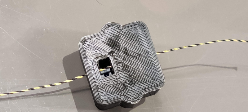
Yes, the distance from one color to the next segment of the same color is approx. 4 mm. The sensor sensibility is tunable by a potentiometer, so you can set the threshold to trigger the sensor only when the yellow segment passes by. It is a simple IR reflection sensor. I've put it in a channel where no other reflections can disturb it. The line runs in front of the sensor in 5 mm distance.
Quote
tobben
Also very interesting to think about potential use during calibration.
Each axis' line buildup could easily be calibrated separately.
I'll try to come up with a solution where we could avoid the inaccuracies of the line buildup method. Either the line pinch method, or if it should fail, a drum with a helical groove. Anyway, the thing I was thinking about with the sensor was to have some kind of closed loop. Even though it would be course, it could be used for synchronizing the line winding with the motor encoders. Or for detecting snapped lines, line flexing or line slipping. And yes, of course for calibration.
I'm aware of the fact, that this isn't foolproof. The line rotation will affect the accuracy. My next idea was to have two sensor perpendicular to each other and some kind of comparison loop to check both readings. Another option could be the laser/led-sensor from a mouse. They are definitely accurate when the line has at least some texture, and I think it wouldn't necessary have to be the black/yellow pattern. I've been looking for a suitable Dyneema line for some time now. There are some guylines with Dyneema core and a polyester jacket. They have also reflective yarn woven into the jacket. It seems that the reflective yarn pattern goes around the jacket and that the pattern is shorter than the black/yellow pattern. The line rotation issue would also be a minor thing, since the braided jacket won't deform under load
|
Re: Motion unit development November 06, 2019 10:20AM |
Registered: 8 years ago Posts: 96 |
Few thoughts on helical drum winches:
The Fraunhofer Institute uses them in their IPAnema cable driven parallel robot. The pictures and concept images show a pretty solid approach and I think it is currently the best way to implement the motion system. But, there's a major misconception when it comes to scalability. The area of end-effector movement is limited by the size of the drum and at some point the inertia will restrict the speed. So, the helical drum concept is more suitable for systems with limited area of movement.
The Hangprinter concept on the other hand is scalable by definition, although it is currently also limited by the size of the spool and the amount of line. I'm still convinced that the parallel grooved GT2-spool will work, it just needs to have more grip. At the moment the line is pinched into a single groove and that's enough for lifting +5kg, but only at slow speeds. Next step: more grooves, more grip. I'll need to buy a bag full of fishing line guide rings

|
Re: Motion unit development November 06, 2019 01:52PM |
Moderator Registered: 10 years ago Posts: 401 |
I've had great results with using ceramic eyelets (like these, or search for "ceramic eyelet" on ebay or similar) instead of fishing line guide rings on HP v4.
Since you're up to buy a lot I thought you wanted to know
Would it work to wind the line around the spool two times, in that track between your GT2 belt?
Edited 2 time(s). Last edit at 11/06/2019 01:56PM by tobben.
torbjornludvigsen.com
Since you're up to buy a lot I thought you wanted to know
Would it work to wind the line around the spool two times, in that track between your GT2 belt?
Edited 2 time(s). Last edit at 11/06/2019 01:56PM by tobben.
torbjornludvigsen.com
|
Re: Motion unit development November 07, 2019 12:39AM |
Registered: 8 years ago Posts: 96 |
That's a great idea! I was already thinking if the fishing line guides would be able to handle the stress at all. The ceramic eyelets are way more compact and you can insert them in a solid block for more resistance to the expected stress.
The current 6 mm wide GT2-belt allows two grooves at maximum. There are also 20 mm wide belts. Or maybe it could work also if the line winds only few times under the belt and then goes few times around the spool in "open" grooves?
The current 6 mm wide GT2-belt allows two grooves at maximum. There are also 20 mm wide belts. Or maybe it could work also if the line winds only few times under the belt and then goes few times around the spool in "open" grooves?

Sorry, only registered users may post in this forum.