|
Kinematic mount with piezo Z sensors March 22, 2019 01:46PM |
Registered: 12 years ago Posts: 1,450 |
I have been trying various ways of getting a kinematic mount for the build stage on one of my printers while combining it with a set of underbed piezo sensors. The latest trials are giving very good results so I am putting some details on the forum in the event that this method will be useful to others. I would also appreciate any feedback about any potential problems that anybody spots.
I noticed on my other printers that beds mounted on sprung adjusters could not be guaranteed to return to the original XY location after a disturbance in the Z plane. Disturbances such as this would occur if a print has a projection that had curled up – for example on an overhang on a PLA print. Lines on the outer surface of a print would quite often appear when doing such a print and microscopic examination showed that a shift of some 10 to 20 microns was the cause. A kinematic mount which returns the build stage to its original position after a disturbance would seem like a good idea but it needs to be combined with the piezo sensors that I use on my other printers.
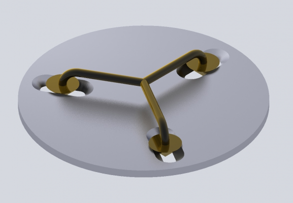
The method I have adopted is based on a Maxwell Kinematic mount although several compromises have been necessary because of pre-existing constraints on the printer. In the theoretical picture below it will be seen that the mechanism consists of cones running in groves with an angled face. - correct Maxwell mount would have hemispheres but space constraints would make for a high point loading and rapid wear. Other compromises were in that the three sensors were a couple of degrees off of 120° and a few mm different from thier common center - all necessitated by linear bearing being where the sensors should go.
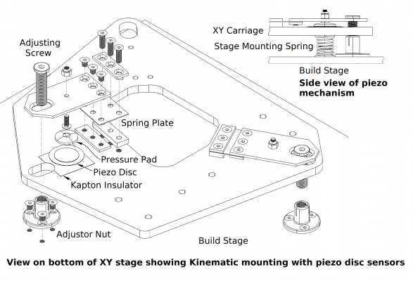
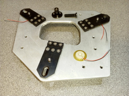
The exploded diagram shows the layout of three sensors (one left off to reduce clutter but can be seen in the photo) The adjusting screws have a 45° chamfer and the lever plate has a matching chamfer on the slot. The nuts into which the adjusting screws fit have slots cut in them to give a sprung clamping action. The mounting springs for the table are shown only in the drawing detail – the working pressure that I have used is about 1kg per mount.
The results of initial tests show that the build stage will consistently return to within 3 microns of the starting position in X, Y and Z – it may be better but that is 1/3 of a small division on my dial indicator. So far I have only used a disturbing deflection of 1mm down directly over each of the mounts while simultaneously pulling the build stage sideways with about 1kg of force. I have also used some uncalibrated taps with the blunt end of a screwdriver. I know that this implementation is overly complicated but it should not be difficult to make something much simpler which still gives an accurate return to the original position
Mike
Sorry, only registered users may post in this forum.


