Controlling a stepper motor with a Ramps 1.4 shield
Posted by Balder
|
Controlling a stepper motor with a Ramps 1.4 shield July 11, 2019 07:56AM |
Registered: 4 years ago Posts: 2 |
Hi,
we want to build a driving robot, which is powerd by 4 stepper motors (one for each wheel). Therefor we bought a kit which included an Arduino Mega 2560 replica, a Ramps 1.4 shield and 5 A4988 stepper driver (https://eckstein-shop.de/3D-Drucker-Set-Kit-fuer-RAMPS-14-RepRap-Mega-2560-5x-DRV8825-12864-LCD-Arduino). The motors are 4 Nema14 stepper motors (https://www.omc-stepperonline.com/de/nema-14-bipolar-1-8deg-40ncm-1-5a-4-2v-35x35x52mm-4-drahte.html). The power supply comes from a 3D-printer and delivers 12V 20A.
Now we have three questions:
1.: Which of the two contacts for the power supply on the shield do we use, the 11A+ or the 5A? We found on another website, that 5A is a minimum and not a maximum when using 12V, correct?
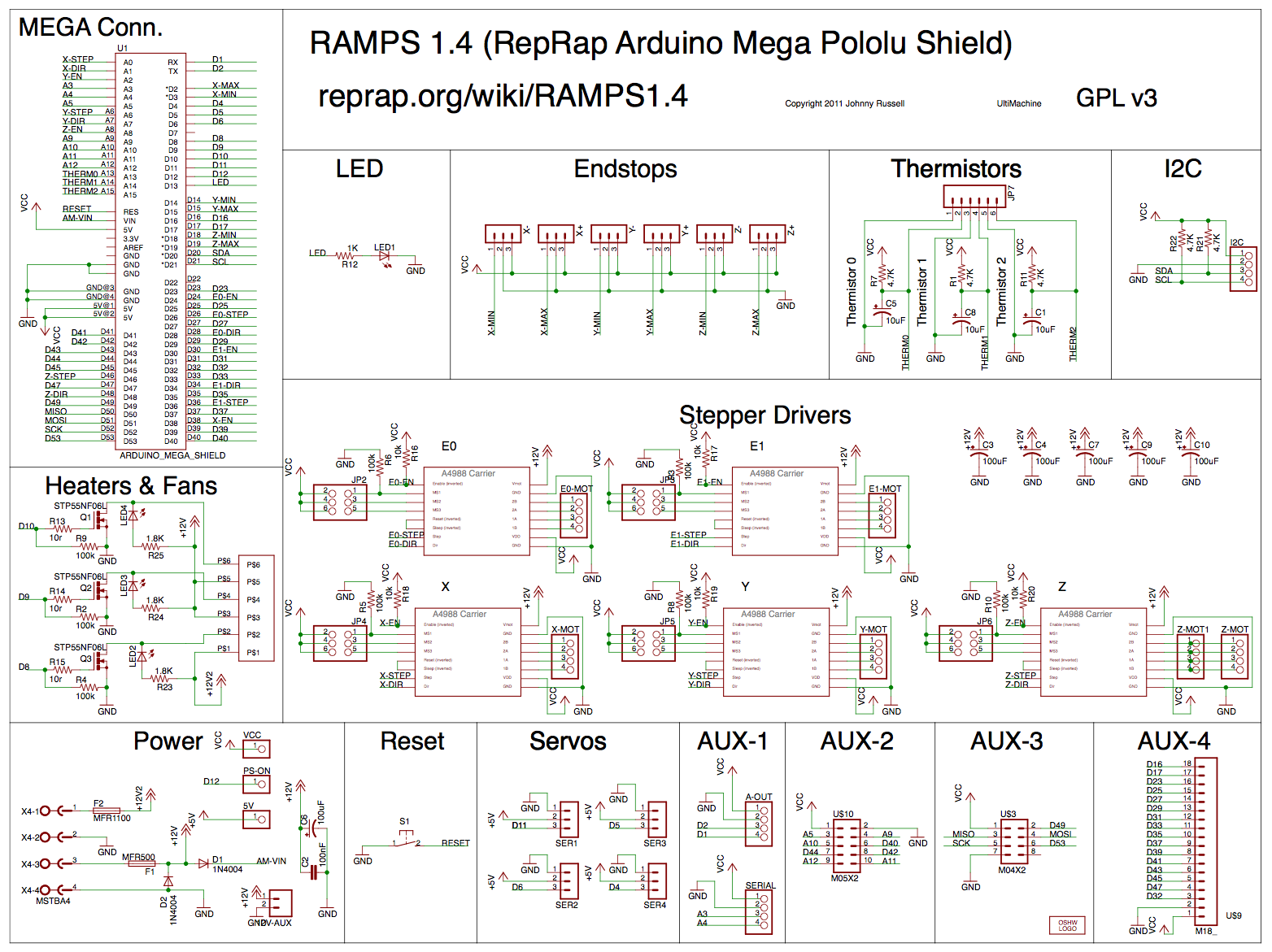
2.: How do we communivate with the motors in or sketch? We found a picture of the circuit (attached) and decided to use pins A0 and A1 because they are connected to X-Step and X-Dir. To controll the movement of the motors we installed the AccelStepper library and wrote a first test sketch:
To be able to see wheter our code is running or not we included the LED switches on and off. But the motor is't moving at all and we can't mesure any voltage between any of the 4 pins for the motor.
Is something wrong with our sketch, or might our shield be damaged?
3.: We are sure that we put the stepper drivers on facing the right way, the jumpers underneath were already on the shield. In theory we know, that you can controll the number of steps per turn with these. But how do you know, if a jumper is set as "yes" or "no"?
Thank you for your help! Since this is our first project with an arduino etc. we are a bit stuck.
Benedikt
we want to build a driving robot, which is powerd by 4 stepper motors (one for each wheel). Therefor we bought a kit which included an Arduino Mega 2560 replica, a Ramps 1.4 shield and 5 A4988 stepper driver (https://eckstein-shop.de/3D-Drucker-Set-Kit-fuer-RAMPS-14-RepRap-Mega-2560-5x-DRV8825-12864-LCD-Arduino). The motors are 4 Nema14 stepper motors (https://www.omc-stepperonline.com/de/nema-14-bipolar-1-8deg-40ncm-1-5a-4-2v-35x35x52mm-4-drahte.html). The power supply comes from a 3D-printer and delivers 12V 20A.
Now we have three questions:
1.: Which of the two contacts for the power supply on the shield do we use, the 11A+ or the 5A? We found on another website, that 5A is a minimum and not a maximum when using 12V, correct?
2.: How do we communivate with the motors in or sketch? We found a picture of the circuit (attached) and decided to use pins A0 and A1 because they are connected to X-Step and X-Dir. To controll the movement of the motors we installed the AccelStepper library and wrote a first test sketch:
#include < AccelStepper.h >                        //had to add the spaces between the < >, otherwise AccelStepper.h wouldn't show in the preview

AccelStepper Motor(1, A0, A1);

void setup() {
  Motor.setMaxSpeed(2000);
  Motor.setSpeed(500);
  pinMode(LED_BUILTIN, OUTPUT);
}

void loop() {
  Motor.runSpeed();
  digitalWrite(LED_BUILTIN, HIGH);
  delay(1000);
  digitalWrite(LED_BUILTIN, LOW);
  delay(1000);
}
To be able to see wheter our code is running or not we included the LED switches on and off. But the motor is't moving at all and we can't mesure any voltage between any of the 4 pins for the motor.
Is something wrong with our sketch, or might our shield be damaged?
3.: We are sure that we put the stepper drivers on facing the right way, the jumpers underneath were already on the shield. In theory we know, that you can controll the number of steps per turn with these. But how do you know, if a jumper is set as "yes" or "no"?
Thank you for your help! Since this is our first project with an arduino etc. we are a bit stuck.
Benedikt
|
Re: Controlling a stepper motor with a Ramps 1.4 shield July 11, 2019 10:14PM |
Admin Registered: 13 years ago Posts: 7,000 |
On the ramps only the heated bed (D8 mosfet) uses the 11amp circuit. Everything else including the steppers is on the 5amp circuit.
NO 5amps is maximum. It has a 5amp polyfuse
The stepper driver also have to be enabled, For X in your example D38 needs to be LOW.
NB the instant the enable is LOW it start powering the steppers. You can just leave it on, but that wastes power and heats up steppers and stepper drivers. If you spend time without motors moving, you should look at disabling the motor to save power.
Take a look at the ramps test code for some hints
I don't know if your planning to use the LCD or not, but if you are here is a demo on how to use it.
code I wrote some time ago.. [github.com]
Edited 4 time(s). Last edit at 07/12/2019 03:01AM by Dust.
NO 5amps is maximum. It has a 5amp polyfuse
The stepper driver also have to be enabled, For X in your example D38 needs to be LOW.
NB the instant the enable is LOW it start powering the steppers. You can just leave it on, but that wastes power and heats up steppers and stepper drivers. If you spend time without motors moving, you should look at disabling the motor to save power.
Take a look at the ramps test code for some hints
#define X_STEP_PIN         54
#define X_DIR_PIN          55
#define X_ENABLE_PIN       38
#define X_MIN_PIN           3
#define X_MAX_PIN           2

#define Y_STEP_PIN         60
#define Y_DIR_PIN          61
#define Y_ENABLE_PIN       56
#define Y_MIN_PIN          14
#define Y_MAX_PIN          15

#define Z_STEP_PIN         46
#define Z_DIR_PIN          48
#define Z_ENABLE_PIN       62
#define Z_MIN_PIN          18
#define Z_MAX_PIN          19

#define E_STEP_PIN         26
#define E_DIR_PIN          28
#define E_ENABLE_PIN       24

#define Q_STEP_PIN         36
#define Q_DIR_PIN          34
#define Q_ENABLE_PIN       30

#define SDPOWER            -1
#define SDSS               53
#define LED_PIN            13

#define FAN_PIN            9

#define PS_ON_PIN          12
#define KILL_PIN           -1

#define HEATER_0_PIN       10
#define HEATER_1_PIN       8
#define TEMP_0_PIN          13   // ANALOG NUMBERING
#define TEMP_1_PIN          14   // ANALOG NUMBERING

void setup() {
  pinMode(FAN_PIN , OUTPUT);
  pinMode(HEATER_0_PIN , OUTPUT);
  pinMode(HEATER_1_PIN , OUTPUT);
  pinMode(LED_PIN  , OUTPUT);

  pinMode(X_STEP_PIN  , OUTPUT);
  pinMode(X_DIR_PIN    , OUTPUT);
  pinMode(X_ENABLE_PIN    , OUTPUT);

  pinMode(Y_STEP_PIN  , OUTPUT);
  pinMode(Y_DIR_PIN    , OUTPUT);
  pinMode(Y_ENABLE_PIN    , OUTPUT);

  pinMode(Z_STEP_PIN  , OUTPUT);
  pinMode(Z_DIR_PIN    , OUTPUT);
  pinMode(Z_ENABLE_PIN    , OUTPUT);

  pinMode(E_STEP_PIN  , OUTPUT);
  pinMode(E_DIR_PIN    , OUTPUT);
  pinMode(E_ENABLE_PIN    , OUTPUT);

  pinMode(Q_STEP_PIN  , OUTPUT);
  pinMode(Q_DIR_PIN    , OUTPUT);
  pinMode(Q_ENABLE_PIN    , OUTPUT);

   digitalWrite(X_ENABLE_PIN    , LOW);
    digitalWrite(Y_ENABLE_PIN    , LOW);
    digitalWrite(Z_ENABLE_PIN    , LOW);
    digitalWrite(E_ENABLE_PIN    , LOW);
    digitalWrite(Q_ENABLE_PIN    , LOW);
}


void loop () {

  if (millis() %1000 <500)
    digitalWrite(LED_PIN, HIGH);
  else
   digitalWrite(LED_PIN, LOW);

  if (millis() %1000 <300) {
    digitalWrite(HEATER_0_PIN, HIGH);
    digitalWrite(HEATER_1_PIN, LOW);
    digitalWrite(FAN_PIN, LOW);
  } else if (millis() %1000 <600) {
    digitalWrite(HEATER_0_PIN, LOW);
    digitalWrite(HEATER_1_PIN, HIGH);
    digitalWrite(FAN_PIN, LOW);
  } else  {
    digitalWrite(HEATER_0_PIN, LOW);
    digitalWrite(HEATER_1_PIN, LOW);
    digitalWrite(FAN_PIN, HIGH);
  }

  if (millis() %10000 <5000) {
    digitalWrite(X_DIR_PIN    , HIGH);
    digitalWrite(Y_DIR_PIN    , HIGH);
    digitalWrite(Z_DIR_PIN    , HIGH);
    digitalWrite(E_DIR_PIN    , HIGH);
    digitalWrite(Q_DIR_PIN    , HIGH);
  }
  else {
    digitalWrite(X_DIR_PIN    , LOW);
    digitalWrite(Y_DIR_PIN    , LOW);
    digitalWrite(Z_DIR_PIN    , LOW);
    digitalWrite(E_DIR_PIN    , LOW);
    digitalWrite(Q_DIR_PIN    , LOW);
  }


    digitalWrite(X_STEP_PIN    , HIGH);
    digitalWrite(Y_STEP_PIN    , HIGH);
    digitalWrite(Z_STEP_PIN    , HIGH);
    digitalWrite(E_STEP_PIN    , HIGH);
    digitalWrite(Q_STEP_PIN    , HIGH);
  delay(1);

    digitalWrite(X_STEP_PIN    , LOW);
    digitalWrite(Y_STEP_PIN    , LOW);
    digitalWrite(Z_STEP_PIN    , LOW);
    digitalWrite(E_STEP_PIN    , LOW);
    digitalWrite(Q_STEP_PIN    , LOW);

}
I don't know if your planning to use the LCD or not, but if you are here is a demo on how to use it.
code I wrote some time ago.. [github.com]
Edited 4 time(s). Last edit at 07/12/2019 03:01AM by Dust.
|
Re: Controlling a stepper motor with a Ramps 1.4 shield July 12, 2019 03:10AM |
Admin Registered: 13 years ago Posts: 7,000 |

|
Re: Controlling a stepper motor with a Ramps 1.4 shield July 12, 2019 08:56AM |
Registered: 4 years ago Posts: 2 |
Thank you for your reply, that should help a ton!
So if 5A is the max, we should defenitly set a stepper drivers to a max of 1A instead of 1.5A which is what the motors can use. But with 4 motors at 1.5A being a total of 6A this would obviously be to much. Do I understand that correctly?
And a very stupid question (but better safe than sorry): We just use the current that we are pulling, so powering our system with a 12V 20A power supply is fine, right?
We also got a reply on a drifferent forum, that told us about setting the max A on the stepper drivers. We followed a tutorial from Pololu to set all five driver one after the other, but somehow on the fourth one it seems we destroyed our Arduino (little bit of smoke, chip got very hot and the Arduino is not longer recognised by my laptop). Could that have happend because there was our sketch (the one from my first post) still on the Arduino running? We can't think of anything else that we did wrong, because as I said the frist three didn't seem to be a problem.
Thanks a lot!
Benedikt
Edited 1 time(s). Last edit at 07/12/2019 08:58AM by Balder.
|
Re: Controlling a stepper motor with a Ramps 1.4 shield July 12, 2019 09:16AM |
Admin Registered: 13 years ago Posts: 7,000 |
Stepper motor currents are not that simple
the 1.5A value given for the steppers is the DC current, (ie the provided voltage 4.2 / the provided resistance 2.8 = 1.5 amp)
your supplying a complicated signal via the stepper drivers not DC.
Setting them to 1.5A will work fine.
Yes a 20A supply is fine, it will only take what it needs.
No a sketch wouldn't do that...
Either Stepper driver was in backwards, or off by one pin, or just dead from the factory
You can also damage the stepper drivers by using a metal screwdriver to adjust the vref, you should use a nonconducting screwdriver.
Sorry, only registered users may post in this forum.