|
Air gauging for filament size April 26, 2021 02:30PM |
Registered: 12 years ago Posts: 1,450 |
This is a continuation of an entry in the General subforum [reprap.org] I thought that it may get more interest in Tech-Talk.
In brief, this is a device for measure the rate of plastic flow in a 3D printer that measures the cross-sectional area of the filament by measuring the restriction to the flow of air through an orifice through which the filament passes. This technology is known as air gauging and is used in industry to make precision measurements.
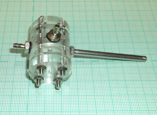
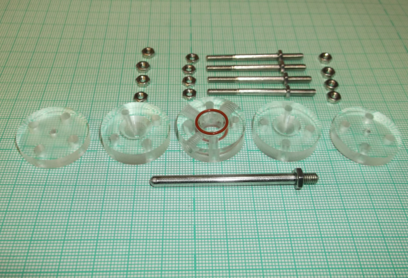
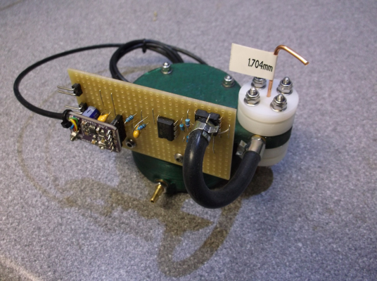
The present status is that a rig has been built to investigate the limits of the method; whether a good accuracy can be achieved in measuring filaments of various characteristics and if that measurement can be used to control the filament feed. Below are photos of the parts of the gauge body and the assembled unit.
Since the results in the earlier tests, I have disassembled the unit and radiused and polished the gauging orifices and fitted ‘O’ rings. The results of these changes have been that there have been fewer anomalous results but also that the restriction to airflow has been reduced by a greater degree than was expected.
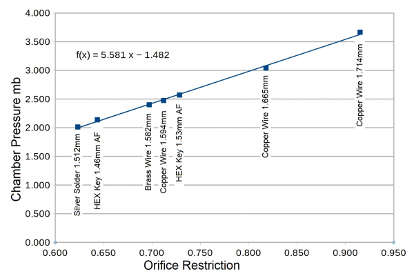
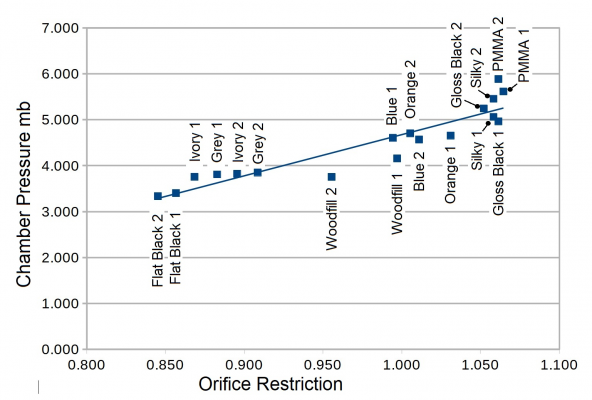
Tests of the rig with hexagonal and round metal test pieces have given good results with accuracy across the range tested of 5µm or better. The results of these tests are shown in the plot below. The X-axis is 1/(Orifice Area – Sample Cross Section) and the Y-axis is chamber backpressure in millibars.
The next stage will be to replace the aquarium pump with a small long-throw loudspeaker and the Digitron manometer with a silicon MEMS pressure sensor. The speaker will be driven at 25 to 40Hz.
Mike
|
Re: Air gauging for filament size April 26, 2021 07:52PM |
Registered: 4 years ago Posts: 285 |
Mike, my only suggestion might be to pull a vacuum, rather than apply pressure. Typical aquarium pumps can be easily converted to do so, and that would make the ambient atmospheric pressure the "calibrated", self correcting, baseline, since their second port is exposed to atmosphere.
Most of the MEMS barometer units from Bosch, STMicro, and the like, will easily register millitorr (if not microtorr) of relative pressure below atmospheric, to an accuracy better than what you apparently need.
Just a thought, and beautiful machining!
Edited 1 time(s). Last edit at 04/26/2021 07:56PM by rq3.
|
Re: Air gauging for filament size April 27, 2021 05:44AM |
Registered: 12 years ago Posts: 1,450 |
Hi rq3, I haven't settled on a driver yet, but I am orbiting around using a speaker to move the air, specifically the Visaton FRS 5 X [www.mouser.co.uk] Loudspeakers have a much longer life than any pump and the output is less affected by things like temperature, humidity and dust. It is true that MEMS barometers are cheaper than gauge or differential MEMS devices and quite often offer greater accuracy. OTOH, as you point out, no great accuracy is needed in the sensor to get a good measurement accuracy. With alternating flow - using a loudspeaker as a driver, the baseline problem disappears and other options such as piezo disks become possible.
Thank you for your comment on the machining, though I am afraid that I make things in Perspex (acrylic) more from self-indulgence than anything else - a bit like eating an unnecessary chocolate. In this case the only reason for using Perspex instead of 3D printing the body is that it is easier to control the exact size of the metering orifices.
Mike
|
Re: Air gauging for filament size April 27, 2021 11:27AM |
Registered: 2 years ago Posts: 2 |
Very cool. Of course you could 3D print parts except for the orifices, and drill them later. But I prefer what you did instead because it looks very cool! A few more seconds of thought on it, machining an orifice in a uniform thickness manufactured sheet as you have it is likely slightly more accurate results than machining into a printed plate, due to the would be less uniform/accurate thickness of the would be printed orifice plate.
|
Re: Air gauging for filament size April 27, 2021 02:14PM |
Registered: 12 years ago Posts: 1,450 |
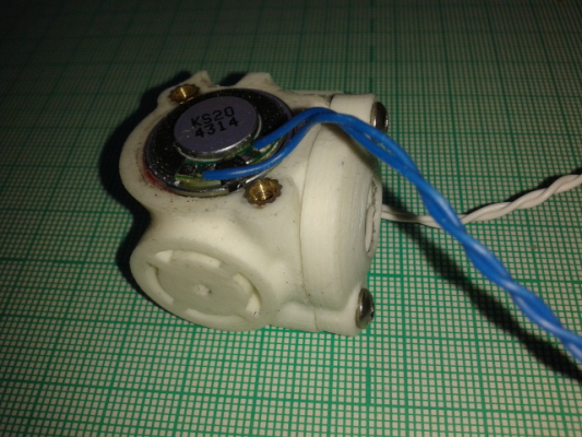
The first iteration of this back in 2016 was 3D printed (picture below) but I used 20mm earphone speakers both as a driver and sensor. As it needed to work with these small speakers which had very limited cone travel, the frequency response of the speakers and the rest of the system made for very peculiar and unpredictable responses. Using much bigger speakers with a long travel on the cone allows a much lower frequency - think of it not so much as making a sound, but more as pushing air one way, making a measurement, then pulling the air back and making another measurement - and repeating about 25 to 40 times a second.
Before any of this though, I have to determine if this will give useful results on the real filament. It certainly works on known diameter wires and Allen keys and gives an output that tracks very closely with cross-sectional area but fluid dynamics can do strange things with rough surfaces: Think of the dimples on golf balls that actually reduce the drag.
Mike
|
Re: Air gauging for filament size May 01, 2021 10:22AM |
Registered: 12 years ago Posts: 1,450 |
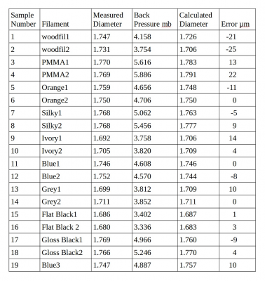
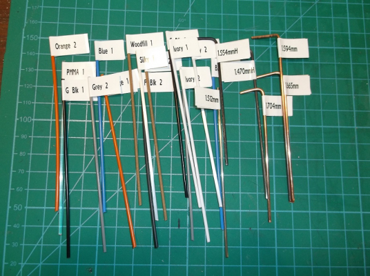
O.K., the first results are in. The first thing of note is that the errors are somewhat more on filament than they were on the metal test pieces. Having said that, an error of 25 microns is just about one thou in Olde English (or one mil in Olde American) It is also about 1.4% of the diameter or 2.8% of the area.
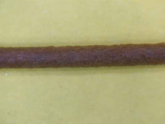
The Woodfill filament gave readings on the air gauge consistently lower than the micrometer readings but this was expected. A quick look at the photo of this filament shows that the micrometer would have measured across the peaks and that this would be different from the mean diameter.
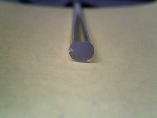
One of the filaments, the PMMA, collapsed to an oval cross-section when heated to straighten it. The flattening was very consistent at 1.95mm by 1.58mm. This is shown in the photo below. The backpressure results were somewhat unexpected as they read higher than predicted from the tests with hexagonal samples.
To see if this ovality error is true with other samples, a piece of the blue filament was flattened between two heated glass plates to give an oval profile of about 1.670mm by 1.790mm and tested. The results do seem to confirm that a flattened profile results in a higher reading - if this is a serious problem remains to be seen
All of the other samples gave results that averaged between the pairs to close to the five micron error predicted by the earlier tests.
The next tests will be with the same samples but with a loudspeaker as a air mover and a MEMS pressure sensor to gather the data.
Mike
|
Re: Air gauging for filament size May 01, 2021 10:58PM |
Registered: 2 years ago Posts: 2 |
Mike, as a machinist myself, I concur with the other poster - beautiful machine work! People don't realize how difficult it can be to machine acrylic and get near perfectly clear cut surfaces like that. I am encouraged at your results to date, just let me know how I can help in the future!
|
Re: Air gauging for filament size May 26, 2021 11:57AM |
Registered: 12 years ago Posts: 1,450 |
A quick report on this project. It is not going too fast although I have managed to put together a loudspeaker air-mover which seems to move enough air at frequencies from 20Hz to 60Hz to get a response on a MEMS pressure sensor. Examination of the changes in waveform of the response is making a return to the constant flow method look attractive.
Recently I have become aware that Murata has produced a micro blower [www.mouser.co.uk] which, although it supplies less than half of the flow I have been using in initial tests, may be usable with a more sensitive pressure sensor.
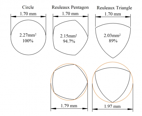
An interesting filament makes me think that the air-gauging methods may be useful. In an earlier post: [reprap.org] I reported that a PLA filament gave a result quite far from all of the others. Sectioning a bit of this filament showed that it had a roughly triangular section. The diagram below shows a shape called a Reuleaux triangle which has the same "diameter" wherever it is measured. Filament measuring methods including one and two position optical or mechanical methods would also only see this "diameter" and give a very false indication of CSA.
Mike
Sorry, only registered users may post in this forum.
