A Very Different Extruder
Posted by rq3
|
A Very Different Extruder May 03, 2021 06:07PM |
Registered: 4 years ago Posts: 285 |
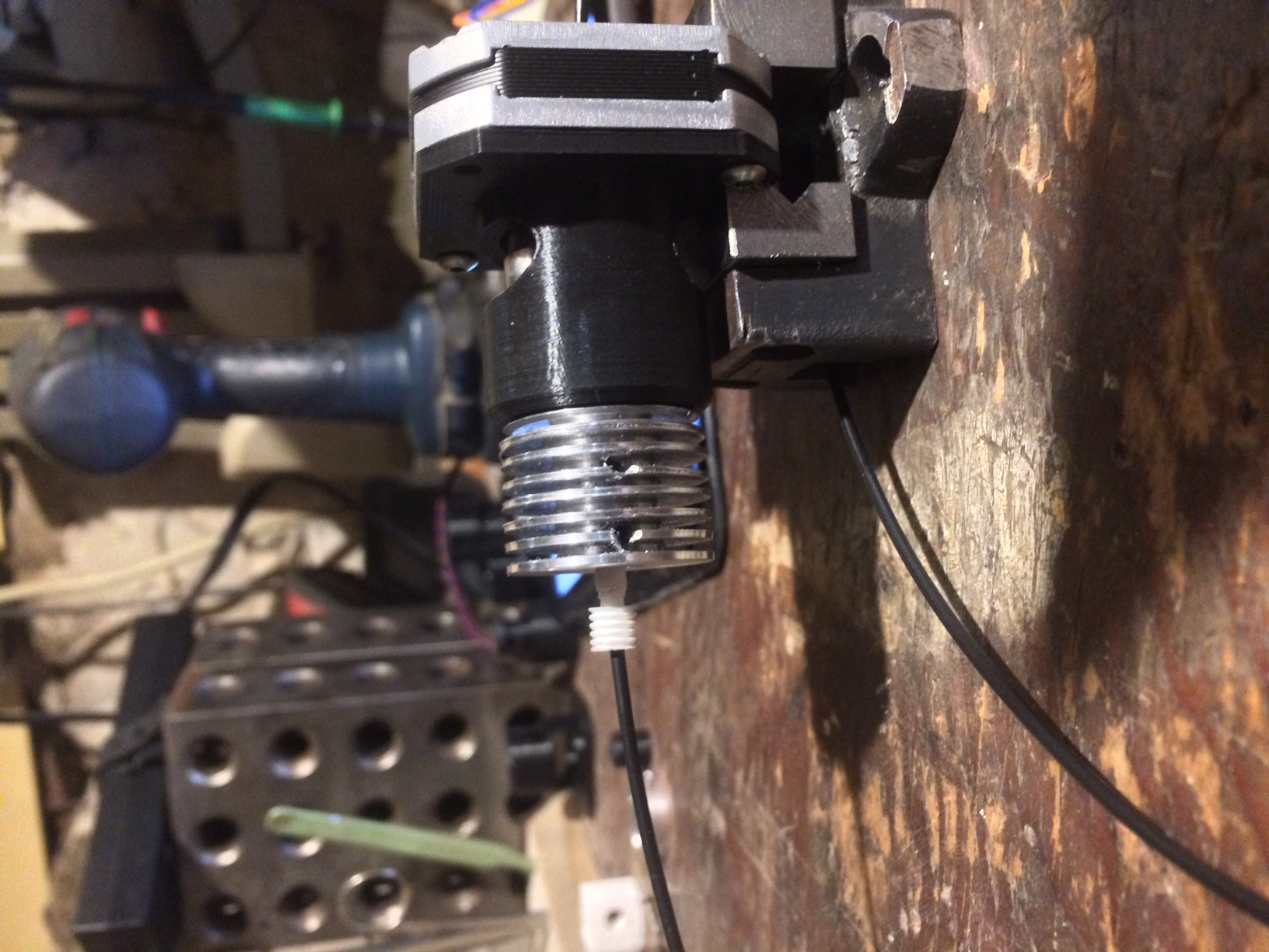
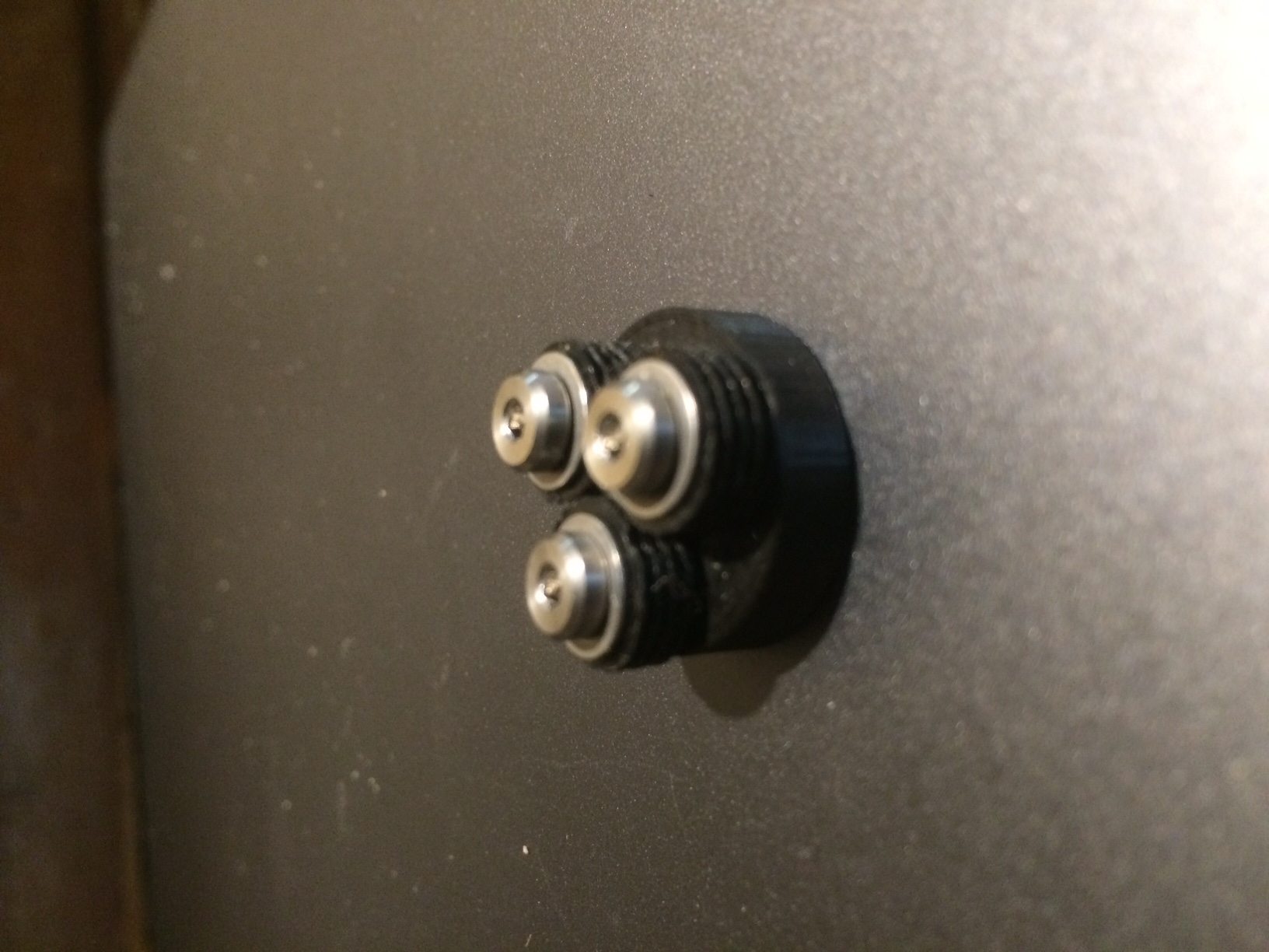
A shot of my prototype extruder, which weighs about 10 grams more than the 70 gram (11.6mm thick Sanyo NEMA 17) motor that drives it.
Upside: Very repeatable, and accurate to 125 nanometers (16 microsteps and a 1.8 degree stepper. 62.5 nanometers with a 0.9 degree stepper). Very light. Very small. No gears or other hard to machine parts. Ferocious mechanical advantage (13.75:1), so a much smaller stepper would be more than adequate.
Downside: It's a bitch to load filament manually, but I'm working on that. It loads and unloads fine under power, with no fiddly filament positioning. Oh, and the motor shaft has to bored for the filament to pass through.
Edited 1 time(s). Last edit at 05/03/2021 06:09PM by rq3.
|
Re: A Very Different Extruder May 03, 2021 08:58PM |
Registered: 9 years ago Posts: 31 |
|
Re: A Very Different Extruder May 04, 2021 10:12AM |
Registered: 6 years ago Posts: 1,007 |
|
Re: A Very Different Extruder May 04, 2021 11:46AM |
Admin Registered: 16 years ago Posts: 13,884 |
... its the combination of the 3 "slanted" bearings, what's propagating the filament, when rotating 
Viktor
--------
Aufruf zum Projekt "Müll-freie Meere" - [reprap.org] -- Deutsche Facebook-Gruppe - [www.facebook.com]
Call for the project "garbage-free seas" - [reprap.org]
Viktor
--------
Aufruf zum Projekt "Müll-freie Meere" - [reprap.org] -- Deutsche Facebook-Gruppe - [www.facebook.com]
Call for the project "garbage-free seas" - [reprap.org]
|
Re: A Very Different Extruder May 04, 2021 03:56PM |
Registered: 6 years ago Posts: 1,007 |
Quote
VDX
... its the combination of the 3 "slanted" bearings, what's propagating the filament, when rotating
So ?
Where is the hot end, and all the rest ?
Seriously, I know how this "works", not a new idea. What would be new is a working and if possible better extruder !
Someone who boasts: "Very repeatable, and accurate to 125 nanometers (16 microsteps and a 1.8 degree stepper. 62.5 nanometers with a 0.9 degree stepper)." better proves it !
Edited 2 time(s). Last edit at 05/04/2021 04:01PM by MKSA.
"A comical prototype doesn't mean a dumb idea is possible" (Thunderf00t)
|
Re: A Very Different Extruder May 04, 2021 04:32PM |
Admin Registered: 16 years ago Posts: 13,884 |
... this was mainly for the filament moving -- don't know, what's on the other side - maybe only the fixation of the hotend ... or a pretty small type ... but the nozzle is missing anyway, as the filament is pointing out ...
Viktor
--------
Aufruf zum Projekt "Müll-freie Meere" - [reprap.org] -- Deutsche Facebook-Gruppe - [www.facebook.com]
Call for the project "garbage-free seas" - [reprap.org]
Viktor
--------
Aufruf zum Projekt "Müll-freie Meere" - [reprap.org] -- Deutsche Facebook-Gruppe - [www.facebook.com]
Call for the project "garbage-free seas" - [reprap.org]
|
Re: A Very Different Extruder May 05, 2021 09:42AM |
Registered: 12 years ago Posts: 1,450 |
I am most intrigued, can you give a few more details? How much of an angle are the bearings at? - This is only hinted at in the photo. What size of bearings? How is the pressure of the bearings on the filament maintained? What is the roughed finish on the gripping surface of the bearings?
Mike
Mike
|
Re: A Very Different Extruder May 05, 2021 11:54AM |
Registered: 4 years ago Posts: 285 |
Mike, this idea is based on the Roh'lix linear actuator. Years ago I purchased several units to see if they were repeatable enough for a 3D printer. They were not. It then occurred to me to grit plate the bearing OD's like a Hewlett Packard drafting plotter. The idea is that the grit particles make tiny pits in the shaft on the first pass, which then automatically align with their respective particle on the reverse pass. Kind of like a sprocket making its own matching chain. This worked very well with a repeatability of about +/- 10 microns on a meter long shaft (the limit of my measurement capability at the time), but I never pursued the printer idea. The original HP idea came from an engineer who ran over a newspaper on his gravel driveway. He noticed that the newspaper tried to "lock" itself back onto the gravel that had dented it.
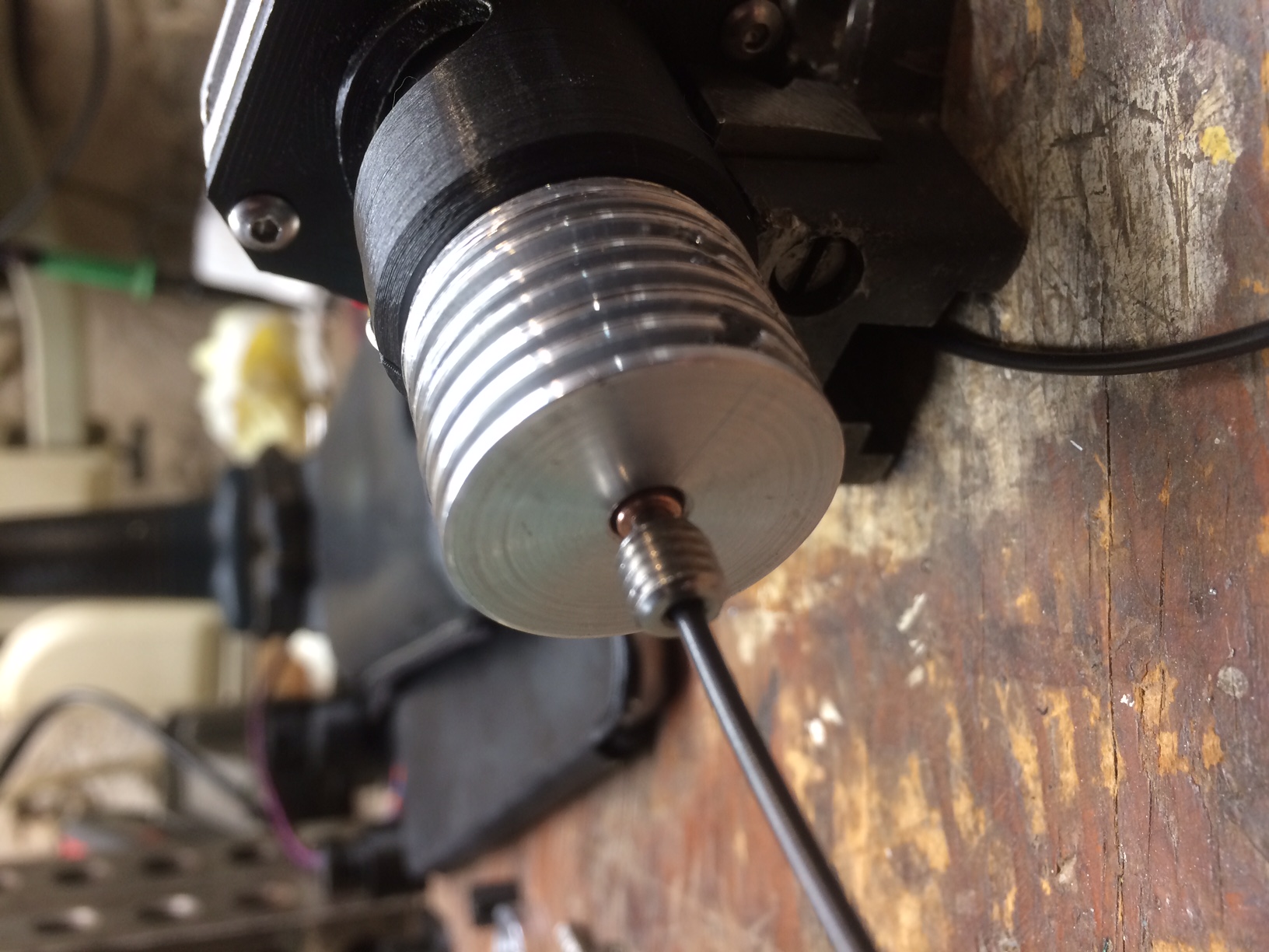
The extruder bearings are 10 mm OD ABEC-5 units, and I initially ran them as is. As expected, there was some slip, but the basic idea worked. The next step was to abrasive blast the OD of the bearings with 400 grit aluminum oxide (as seen in the photo). That was a major improvement. While repeatability is not perfect, the unit can lift just under 4 kilograms by the ABS filament in the picture. Next, I plan to grit coat the bearing OD's with thinned epoxy and aluminum oxide, and as a last step I have contacted the company that invented the diamond particle electroplate process. It costs about 62 cents to have each bearing diamond particle coated, but the set-up charges are not at all insignificant. I fully expect that diamond grit would work just like my early Roh'lix experiments and result in non-repeatability that can be ignored.
The bearing angle can be anything up to about 30 degrees, and is what determines the feed rate per shaft revolution (simply arc tan [rise/run]). The prototype is set at 4.16 degrees (theoretically), for an extrusion rate of 1 mm per 2.5 shaft rotations on a 1.75 mm filament. It's pretty close to that, so the math works, and can be fine tuned with the steps/mm in the firmware.
One of the bearings is spring loaded by the slot designed into the carrier. The compliance is enough to deal with a severely oval shaped filament (+/- 0.25 mm). It's very difficult to load, or unload, filament by just pushing or pulling it. But if you turn the motor on and gently introduce the filament, it just grabs it and sucks it in. I don't think this idea would work on very flexible filaments, as there is some torque on the filament from the bearings, but who knows. I don't have any flexible filament to check that.
I also machined a bearing carrier out of aluminum (see attached photo), which was interesting, but the prototype carrier is printed in PLA at a 0.05 mm layer height. The little stepper is rated for 1 amp per phase, but I am currently running it at 0.3 amps and it barely gets warm, so the PLA works for experimental purposes. The STL file for the carrier is attached as a Zip file so as not to exceed the 800KB limit.
Edited 1 time(s). Last edit at 05/05/2021 12:09PM by rq3.
|
Re: A Very Different Extruder May 05, 2021 02:52PM |
Registered: 12 years ago Posts: 1,450 |
Thank you for all of the detail. My only remaining question is with regard to the "nest" between the three bearings: With a bearing diameter of 10mm there is only enough space for a filament larger than 1.55 mm in diameter - barely enough to get a grip on 1.75mm filament. With any clearance between the bearings, and in particular, if there is a diamond coating, the nest may become too big to get any grip on the filament. SKF does a needle bearing of 8mm od (K 5×8×10 TN) which would work but doesn't deal with the end thrust - and needs a hardened 5mm shaft.
I will follow this with great interest.
Mike
I will follow this with great interest.
Mike
|
Re: A Very Different Extruder May 05, 2021 04:04PM |
Registered: 4 years ago Posts: 285 |
With 10 mm OD bearings equidistantly spaced on a 11.6 mm circle as the center locator, they each try to "bite" the filament by 0.075 mm. It doesn't sound like much, but if you draw it out, you'll see it's an appreciable amount of the filament circumference. You could go to an 11.55 mm mount diameter and get a 0.1 mm bite on each bearing, and there would still be clearance at the bearing periphery. Keep in mind that all three bearings are applying extrusion force to the filament, not just one.
In any case, it works well enough to pursue further, even without yet grit or diamond coating the bearings.
A needle bearing could work, on a hardened precision shoulder screw as a shaft (that's what I'm using). But you'd have to deal with end play and axial thrust loads. My bearings are 4 mm thick on a 5 mm shoulder length precision shoulder screw. There is a 0.5 mm thick precision shim under the head of the screw, and a 0.65 mm thick belleville spring under the bearing, which is compressed 0.15 mm when the screw is tightened. That eliminates end play without interfering with the bearing rotation.
I picked the 10 mm bearings because they are inexpensive commodity items available in ABEC 5,7, and even 9 quality., and they were the largest bearing that would fit. Smaller ball bearings are readily available. The ones I am using happen to have silicon nitride balls, just because that's what they had in stock. The nitride balls are stiffer and lighter than any steel, and don't mind high temperatures or insufficient lubrication, none of which is an issue here.
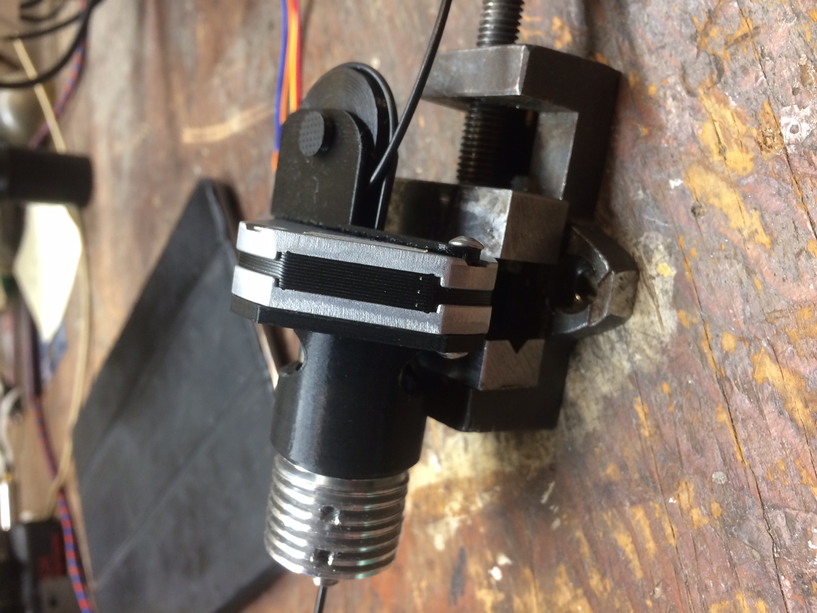
Attached are shots of a mock-up, with the groove mount heatsink adapter, heatsink, heat break, heater block, and nozzle attached. You can just barely see the bearings peeking out of the slots in the groove mount adapter. The slots let me rotate the bearings with my finger tips if necessary. The whole thing is clamped in a miniature machinists vice for stability while I play with it. The filament is visible on the right where it enters the hollow motor shaft. This is designed to go on my delta printer, where I hope it will replace a stock assembly roughly 4X larger and 6X heavier.
Edited 3 time(s). Last edit at 05/05/2021 04:50PM by rq3.
In any case, it works well enough to pursue further, even without yet grit or diamond coating the bearings.
A needle bearing could work, on a hardened precision shoulder screw as a shaft (that's what I'm using). But you'd have to deal with end play and axial thrust loads. My bearings are 4 mm thick on a 5 mm shoulder length precision shoulder screw. There is a 0.5 mm thick precision shim under the head of the screw, and a 0.65 mm thick belleville spring under the bearing, which is compressed 0.15 mm when the screw is tightened. That eliminates end play without interfering with the bearing rotation.
I picked the 10 mm bearings because they are inexpensive commodity items available in ABEC 5,7, and even 9 quality., and they were the largest bearing that would fit. Smaller ball bearings are readily available. The ones I am using happen to have silicon nitride balls, just because that's what they had in stock. The nitride balls are stiffer and lighter than any steel, and don't mind high temperatures or insufficient lubrication, none of which is an issue here.
Attached are shots of a mock-up, with the groove mount heatsink adapter, heatsink, heat break, heater block, and nozzle attached. You can just barely see the bearings peeking out of the slots in the groove mount adapter. The slots let me rotate the bearings with my finger tips if necessary. The whole thing is clamped in a miniature machinists vice for stability while I play with it. The filament is visible on the right where it enters the hollow motor shaft. This is designed to go on my delta printer, where I hope it will replace a stock assembly roughly 4X larger and 6X heavier.
Edited 3 time(s). Last edit at 05/05/2021 04:50PM by rq3.
|
Re: A Very Different Extruder May 05, 2021 05:03PM |
Admin Registered: 16 years ago Posts: 13,884 |
... for giving the rollers surface a better "grip" you could laserengrave the surface with a raster -- did this for testing with DIY-gears for filament or wire transport - works pretty good, as the laser creates sharp "coarse" edges at the engraving lines and "hardens" the steel, so the surface gives a perfect grip!
Here two images while laser-engraving and finished "gear"-surface -- no problem to make this with the bearings surface too:
Edited 1 time(s). Last edit at 05/05/2021 05:04PM by VDX.
Viktor
--------
Aufruf zum Projekt "Müll-freie Meere" - [reprap.org] -- Deutsche Facebook-Gruppe - [www.facebook.com]
Call for the project "garbage-free seas" - [reprap.org]
Here two images while laser-engraving and finished "gear"-surface -- no problem to make this with the bearings surface too:


Edited 1 time(s). Last edit at 05/05/2021 05:04PM by VDX.
Viktor
--------
Aufruf zum Projekt "Müll-freie Meere" - [reprap.org] -- Deutsche Facebook-Gruppe - [www.facebook.com]
Call for the project "garbage-free seas" - [reprap.org]
|
Re: A Very Different Extruder May 05, 2021 05:15PM |
Registered: 4 years ago Posts: 285 |
|
Re: A Very Different Extruder May 05, 2021 05:26PM |
Registered: 4 years ago Posts: 285 |
Quote
MKSA
So ?
Where is the hot end, and all the rest ?
Seriously, I know how this "works", not a new idea. What would be new is a working and if possible better extruder !
Someone who boasts: "Very repeatable, and accurate to 125 nanometers (16 microsteps and a 1.8 degree stepper. 62.5 nanometers with a 0.9 degree stepper)." better proves it !
Actually, I don't have to "prove" anything, and I'm not boasting, just stating simple physics. It's just an idea that appears to work. You're more than welcome to ignore it, or use the idea as you see fit. Golly, you could even put "all the rest" on it, and call the entire thing an extruder!
A piece of paper, a pencil, and some trig tables will confirm the figures. Or maybe you can even use a calculator?
|
Re: A Very Different Extruder May 05, 2021 06:23PM |
Admin Registered: 16 years ago Posts: 13,884 |
... this "gears-marking" was with a 20Watt fiber-laser, galvo-head with 110x110mm and turning axis, I've developed for the last company (my actual fiber-laser at home is a 30Watt) ...
Viktor
--------
Aufruf zum Projekt "Müll-freie Meere" - [reprap.org] -- Deutsche Facebook-Gruppe - [www.facebook.com]
Call for the project "garbage-free seas" - [reprap.org]
Viktor
--------
Aufruf zum Projekt "Müll-freie Meere" - [reprap.org] -- Deutsche Facebook-Gruppe - [www.facebook.com]
Call for the project "garbage-free seas" - [reprap.org]
|
Re: A Very Different Extruder May 06, 2021 12:11PM |
Registered: 9 years ago Posts: 31 |
Since nothing is keeping the filament from twisting on its own axis, won't a given extrusion pressure always result in some amount of torsional rotation of the filament instead of purely lateral displacement? This would be most obvious in soft/flexible materials, as you mention, but I'm curious if it's significant enough to cause print artifacts in stiffer materials as well. The effect could be mitigated with an additional counter-rotating head (albeit at double the weight), or a passive pair of pinch-rollers to hold the filament straight (I think the Fuselab3D extruder uses this approach). Eagerly awaiting first prints! 
|
Re: A Very Different Extruder May 07, 2021 03:01AM |
Registered: 6 years ago Posts: 1,007 |
Quote
rq3
..
A piece of paper, a pencil, and some trig tables will confirm the figures. Or maybe you can even use a calculator?
I can confirm the angle you computed is correct. Not bad if you used trig tables
Will check back in a year.
"A comical prototype doesn't mean a dumb idea is possible" (Thunderf00t)
|
Re: A Very Different Extruder May 07, 2021 06:19AM |
Registered: 12 years ago Posts: 1,450 |
I looked at the FuseLAB extruder on [www.youtube.com] - explanation of the mechanism of working from about 4:30. It is a bit chunky and complicated - rq3s extruder is smaller and simpler and more likely to be the basis of a RepRapable extruder.
btw, MKSA - your new mildly humorous sarcasm is better than your normal unrelentingly negative sarcasm - there is hope for you yet but please dump the stupid sigline about the dumb prototype.
Mike
btw, MKSA - your new mildly humorous sarcasm is better than your normal unrelentingly negative sarcasm - there is hope for you yet but please dump the stupid sigline about the dumb prototype.
Mike
|
Re: A Very Different Extruder May 09, 2021 04:27PM |
Registered: 4 years ago Posts: 285 |
A couple of observations after playing with this idea, for any one else who may want to pursue it. I tried grit coating the bearing OD's by rolling them on a film of thinned JB-Weld epoxy on a glass plate, and then into a dusting of 400 grit aluminum oxide. The process worked fine, but oddly didn't really make the pull-out force on the filament much better, and made the repeatability MUCH worse (several mm over 400 mm). I think sparsely spaced diamond particles is the way to go, but...
The orientation of the bearing axles is critical. I ended up printing a small jig so that when I tapped the holes for the bearing axle screws, they would be precisely aligned. The bearings now just barely kiss each other, and one is mounted on an adjustable cantilever spring. With the grit and epoxy cleaned off of the bearings, the filament broke at about 6 pounds of pull force (using a calibrated force gauge), and the filament never slipped in the bearings (1.75 mm diameter ABS from Filament Direct, very old stuff).
I'm also pretty shocked at how non-round this filament is!
At this point I need to machine an aluminum heatsink for the assembly, and see if I can actually print something with it. If so, I'll consider having the bearing OD's diamond gritted, but I don't think it's worth the expenditure yet, as the extrusion force with just naked bearings is much higher than I expected. IF the bearing axles are properly aligned.
Attached is the FreeCAD file for the most successful bearing carrier so far. It needs to be 1 mm thicker, as I thought I could get away with shaving a millimeter off of the height, but I need the screw head clearance.
Edited 1 time(s). Last edit at 05/09/2021 04:36PM by rq3.
|
Re: A Very Different Extruder May 10, 2021 06:00AM |
Registered: 12 years ago Posts: 1,450 |
Just a passing thought: Is it possible that this would work with only two wheels? At first blush, this sounds silly as the filament would pop out sideways as very under-constrained. However, the sideways force may possibly be easily constrained with guides if they were slippy enough or maybe with guide bearings just beyond the ends of the drive bearings. The question is, how big should the wheels be? There would be no sideways force with infinitely big wheels but perhaps 20mm is close enough to infinitely big for our purposes.
Mike
Edited 1 time(s). Last edit at 05/10/2021 06:01AM by leadinglights.
Mike
Edited 1 time(s). Last edit at 05/10/2021 06:01AM by leadinglights.
|
Re: A Very Different Extruder May 10, 2021 06:35PM |
Registered: 4 years ago Posts: 285 |
Quote
leadinglights
Just a passing thought: Is it possible that this would work with only two wheels? At first blush, this sounds silly as the filament would pop out sideways as very under-constrained. However, the sideways force may possibly be easily constrained with guides if they were slippy enough or maybe with guide bearings just beyond the ends of the drive bearings. The question is, how big should the wheels be? There would be no sideways force with infinitely big wheels but perhaps 20mm is close enough to infinitely big for our purposes.
Mike
Hi Mike, interesting idea, but I'm not sure I see the benefit, other than allowing larger bearings? As you say, the two drivers would still try to squirt the filament out sideways, so you need a third constraint of some kind to be a truly kinematic system. It may as well be a low friction bearing. And three bearings "automagically" align themselves to the filament diameter, even if it is not constant. And they all take an active part in driving the filament.
It's interesting to see the mechanism in action. If you visualize the filament path, it's very much like a snake doing a sidewinder motion in sand, but the "wiggle" is only very small fractions of a millimeter (about 0.025 millimeter with the latest bearing carrier). It's also interesting introducing the filament to the drive. I just turn the stepper on, and gently insert the filament into the hollow motor shaft. When it meets the bearings, even if they are adjusted very tight, it literally sucks the filament in. No spring loaded levers to retract. I can see this being evolved into an auto-loading extruder pretty easily.
The latest bearing carrier has a filament adjustment screw, which is very effective, and very sensitive. I'm currently using some Matterhackers PLA as test material. It is considerably "rounder" and more consistent than the antique, no-name ABS I was using before.
I really need to buckle down and machine a heatsink for this idea, and actually try it on one of my printers. Probably tomorrow. I have the aluminum bar stock, but I'm going to have to grind a custom plunging tool for the heatsink fins.
Edited 2 time(s). Last edit at 05/11/2021 09:31PM by rq3.
|
Heatsink done and mounted May 11, 2021 09:08PM |
Registered: 4 years ago Posts: 285 |
6061 aluminum, 19 grams, probably half of which is the darn groove mount end not visible in the photo.
Also attached is the FreeCad file for the latest, and hopefully last, bearing carrier. I've printed 19 of these things, with various tweaks, and machined one from 7075 aluminum. The cantilever spring slot is wider (0.5mm instead of 0.25mm), and there is a 3mmx0.5x5mm adjustment screw for the filament tension, although I haven't felt the need to use it yet. I went back to a total thickness of 6mm to get clearance for the adjustment screw head. I print this at 0.05 layer thickness in PLA, with 100% concentric infill. I think this object machined in 7075 aluminum would be ideal, as the spring constants work for both materials.
I may as well machine a tri-metal heatbreak while I'm at it. Tomorrow, if I can find my grade 5 titanium bolts. I don't mind turning and drilling titanium. Threading it is a completely different matter, so I like to start with threaded bolts and go from there when I can.
I also have a design for a fine silver heat block that uses industrial standard ring mount temp sensors, but the current price of pure silver casting grain will probably put that on the back burner for now.
OFHC copper rod and 12.5 gauge 316 SS hypo tube I have "in stock" for the heatbreak. Sometimes I forget what crap I've collected over the decades. I know I have quite a bit of sterling silver somewhere, but that's no good.
Edited 6 time(s). Last edit at 05/11/2021 09:51PM by rq3.
|
Tri-Metal Heatbreak May 12, 2021 03:39PM |
Registered: 4 years ago Posts: 285 |
Based on the E3D V5 units, but dimensioned for my heatsink. Grade 5 titanium hot end threads, OFHC copper cold end, connected with 0.009 inch wall 316 stainless hypodermic tubing. A lot easier to make than the heatsink!
I think I'll pop this puppy on a printer and try it out this weekend.
Edited 1 time(s). Last edit at 05/12/2021 03:41PM by rq3.
I think I'll pop this puppy on a printer and try it out this weekend.
Edited 1 time(s). Last edit at 05/12/2021 03:41PM by rq3.
|
Anti-Torque May 17, 2021 06:49PM |
Registered: 4 years ago Posts: 285 |
As expected, this extruder idea tries to twist the filament to the extent of the bearing torque spec, which is milligram-millimeters, not much but enough to have to be dealt with. I tried various clamps and clips, but have decided that a simple single loop in the filament serves the purpose very well. It doesn't interfere with feed and retraction repeatability, and weighs about 5 grams, including the stainless steel mounting screws.
I was hoping to try this on my printer this weekend, but this small detail got in the way.
I was hoping to try this on my printer this weekend, but this small detail got in the way.
|
Re: A Very Different Extruder May 23, 2021 05:32PM |
Registered: 4 years ago Posts: 285 |
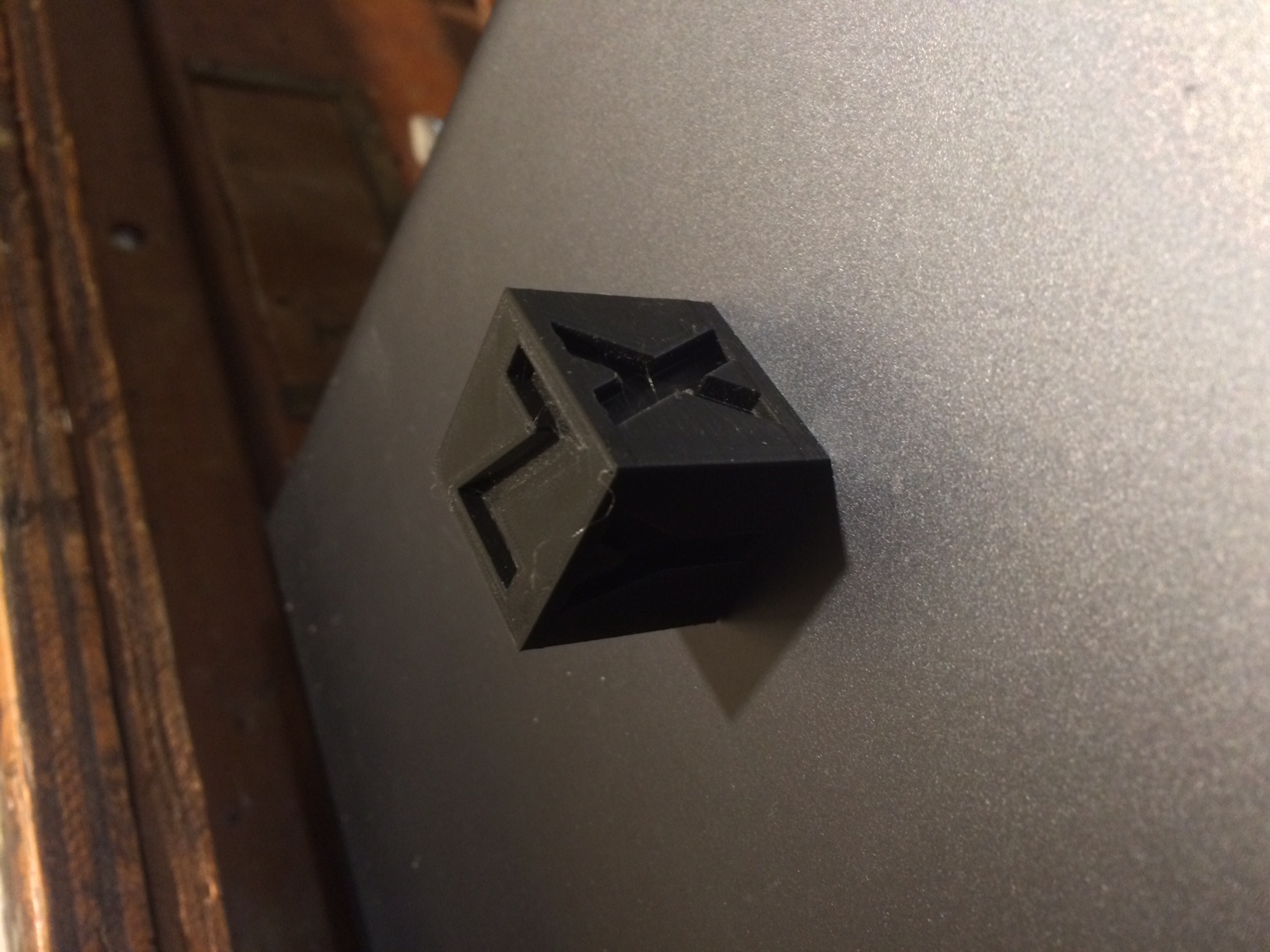
So, I mounted this thing on my delta, calibrated the extrusion rate, and printed a cube (results attached). My usual extruder is an almost stock Anycubic, which is a BMG clone, and quite nice and reliable. Some time ago, I converted all of the printer motors to 0.9 degree step units, and the current extruder needs 830 steps per millimeter.
The "very different extruder" (VDE for short) needs 11,100 steps per millimeter. While it prints fine, it has obvious issues with retraction (acceleration at those step pulse rates). I'm also battling the fact that I've changed several variables at once: the extrusion method, the heat sink, and the heat break. All of those add up to a lot of tail chasing when printing PLA for testing, especially the new heat break and retraction.
I could just make a new bearing carrier with a more severe bearing angle to help alleviate the retract acceleration issue. I did find that the original PLA bearing carrier softened too much from the stepper warmth to maintain its "springiness, so the final, actually printing, unit was made from ABS.
BUT:
During printing, and actually watching the VDE in action, I had a "face palm, what the hell was I thinking", moment. There is a MUCH easier way to build this idea that doesn't involve grit on bearings, weird shaft and bearing angles, or cantilevered springs machined into the bearing carrier. I printed prototypes (again in PLA), and the basic idea is good, though not yet "printer installation worthy". I've ordered a few new parts (mainly smaller bearings (8mm OD instead of 10mm), and will report back. This ain't over yet!
|
Re: A Very Different Extruder May 24, 2021 06:43AM |
Registered: 12 years ago Posts: 1,450 |
|
Re: A Very Different Extruder May 25, 2021 02:19PM |
Registered: 7 years ago Posts: 363 |
Well, you've certainly piqued my interest.
So, I've been mulling this concept over in my head a bit and had an idea, although I'm not sure how feasible this would be.and may result in more twisting of the filament, but what if the bearings rotation axis was slightly canted to apply the corner edge of the bearing to the filament with some light machining/grinding/sanding to provide a sharp 90 degree edge to bite into the filament instead of relying on oxide grit? It would imprint the helix into the filament potentially but would be a simpler and more repeatable process since you're not doing anything that alters the OD of your bearing.
Additionally, I'm curious why you chose to continue using 16 microsteps, If indeed you are operating 11000 microsteps per millimeter why not use 8x or 4x microstepping instead?
Edited 1 time(s). Last edit at 05/27/2021 08:33AM by obelisk79.
|
Re: A Very Different Extruder June 02, 2021 03:54PM |
Registered: 4 years ago Posts: 285 |
@obelisk79, great minds think alike. While watching the VDE in action, it occurred to me (face palm) that, rather than have a canted bearing that relies on surface friction, I needed a threaded sleeve on the OD of a smaller bearing. An Archimedes screw, if you will. Since my lathe doesn't having threading capabilities, a local machine shop is doing that for me. A prototype works on the bench, and I'm looking forward to the "real thing", hopefully this week. This also means that the bearings aren't canted at all, so the machining is stupid simple.
As to your other question: my primary printer is an Anycubic delta, and the A4988 stepper drivers are soldered to the motherboard. Changing the step function involves fiddly surface mount soldering which I'm not willing to do unless this idea pans out.
Edited 1 time(s). Last edit at 06/02/2021 03:55PM by rq3.
|
Re: A Very Different Extruder June 02, 2021 04:19PM |
Registered: 7 years ago Posts: 363 |
Do you have a screenshot of the updated design? I've been mocking up some simple experiments using 10deg pitch with some 683zz bearings and heatshrink to provide friction, I'm still dialing in tolerances on my design/print.
Another thing I've been struggling to calculate is the amount of relative force this setup provides.
the bearing, to filament diameter comes out to a ratio of roughly 4.28. But that isn't the only factor in play. The rotational torque then needs to be converted into axial force AND the bearing pitch should have an affect in final pushing force applied. If only I studied mechanical engineering instead of joining the Navy *hooray for beer!*
Edited 1 time(s). Last edit at 06/02/2021 04:30PM by obelisk79.
|
Re: A Very Different Extruder June 02, 2021 04:32PM |
Registered: 4 years ago Posts: 285 |
Quote
obelisk79
Do you have a screenshot of the updated design? I've been mocking up some simple experiments using 10deg pitch with some 683zz bearings and heatshrink to provide friction, I'm still dialing in tolerances on my design/print.
Attached is a shot of the prototype bearing carrier, printed in PLA just to see if the idea would work (it does). The bearings are mounted "normally" (not canted), and have 1mm pitch threaded sleeves which will bite into the filament as they rotate. The threads are being machined with no flat on the apex as a thread normally would. They come to a sharp point. With threads 10mm in diameter, mounted 120 degrees apart on a 10.55mm circle, they should bite into the filament 0.1mm (0.004 inch). I've also added a common "spider plate" on top of the bearings and under the screw heads to keep the bearing screws from spreading apart under load.
I think this is a much more straightforward and elegant design, but we'll see.
Edited 2 time(s). Last edit at 06/02/2021 04:40PM by rq3.
|
Re: A Very Different Extruder June 02, 2021 04:43PM |
Registered: 7 years ago Posts: 363 |
I like it, I was concerned that the screw being on a bearing would just sit in place as the carrier spins around the filament, but if its working like this then I stand corrected. My brain can only visualize so much I guess. What about just using a single stationary grub screw with 2 bearings as an alternative (and more off-the-shelf) approach? I think that could work well.
I might go to a hardware store tonight to see what they have on the shelves to try that idea out.
I might go to a hardware store tonight to see what they have on the shelves to try that idea out.

Sorry, only registered users may post in this forum.