A Very Different Extruder
Posted by rq3
|
Re: A Very Different Extruder June 02, 2021 05:13PM |
Registered: 4 years ago Posts: 285 |
Quote
obelisk79
I like it, I was concerned that the screw being on a bearing would just sit in place as the carrier spins around the filament, but if its working like this then I stand corrected. My brain can only visualize so much I guess. What about just using a single stationary grub screw with 2 bearings as an alternative (and more off-the-shelf) approach? I think that could work well.
I might go to a hardware store tonight to see what they have on the shelves to try that idea out.
I can't visualize the two bearings spinning around a stationary grub screw. My head hurts

|
Re: A Very Different Extruder June 02, 2021 09:53PM |
Registered: 9 years ago Posts: 31 |
I don't see how this newer design actually drives the filament-- it seems to me that the threads on the bearing sleeves would simply impress a "///////////" pattern on the cylindrical surface of the filament (much like a knurling tool) as they revolve around it, without any of the desired axial movement. The design will only function if the bearings don't actually rotate-- at that point the whole carrier would act as a solid, thread-forming nut being twisted onto the filament.
|
Re: A Very Different Extruder June 02, 2021 10:05PM |
Registered: 7 years ago Posts: 363 |
This is my concern as well. My proposal was to keep the 3 bearing configuration, however swap out a single bearing for a stationary threaded rod to use its thread to drive the filament.(I proposed a hex driven grub/set screw) I actually purchased 3 screws and am going to try using 3 stationary threaded sections without any bearings configured in a similar fashion to a thread die, instead of my initially proposed 1. I'm printing a prototype carrier to prove if it works. I'll take pictures of my series of failures along the way. If nothing else, it should entertain people who like to mock backyard engineers such as myself.
Edited 2 time(s). Last edit at 06/02/2021 10:12PM by obelisk79.
Edited 2 time(s). Last edit at 06/02/2021 10:12PM by obelisk79.
|
Re: A Very Different Extruder June 02, 2021 10:39PM |
Registered: 9 years ago Posts: 31 |
@obelisk79: I admittedly did not fully comprehend your post the first time around, but now I see what you mean  It will be interesting to see the concept in action.
My own "backyard engineering" idea, partially inspired by this bearing concept, is to replace the canted bearings with a helical coil (e.g. a compression spring) and bearing balls of an appropriate size as to create a recirculating ball-nut of sorts to drive the filament directly. Using a helical coil as a bearing race should make it possible to use a split housing with a screw to dial in the clamping force.
It will be interesting to see the concept in action.My own "backyard engineering" idea, partially inspired by this bearing concept, is to replace the canted bearings with a helical coil (e.g. a compression spring) and bearing balls of an appropriate size as to create a recirculating ball-nut of sorts to drive the filament directly. Using a helical coil as a bearing race should make it possible to use a split housing with a screw to dial in the clamping force.
|
Re: A Very Different Extruder June 02, 2021 10:41PM |
Registered: 4 years ago Posts: 285 |
Quote
NathanaelXYZ
I don't see how this newer design actually drives the filament-- it seems to me that the threads on the bearing sleeves would simply impress a "///////////" pattern on the cylindrical surface of the filament (much like a knurling tool) as they revolve around it, without any of the desired axial movement. The design will only function if the bearings don't actually rotate-- at that point the whole carrier would act as a solid, thread-forming nut being twisted onto the filament.
Well, I've already actually printed with my original prototype, with canted bearings (rotating inclined planes) friction driving the filament. I also know from many hours of machining, that a knurling tool (a rotating inclined plane) will drive itself axially up the work piece if allowed to do so (as you say, like a nut spinning on a bolt). I would think that the work piece in a lathe would advance axially if the knurling tool were spun around it without advancing axially itself. Rotary thread roll forming works in exactly that fashion.
In all cases, there is an axial force; it's just a matter of which piece is revolved, and which is constrained. In any case, it's all food for thought, and I should be able to shoot myself in the foot later this week. I'm going to visit the machine shop tomorrow to see how they are getting along with my threaded sleeves. It's a 20 minute job, and should certainly be done by now!
|
Re: A Very Different Extruder June 02, 2021 11:01PM |
Registered: 7 years ago Posts: 363 |
|
Re: A Very Different Extruder June 02, 2021 11:16PM |
Registered: 4 years ago Posts: 285 |
You guys are fantastic! Having other interpretations of a wing nut idea can only be a good thing! And the YouTube videos demonstrate the real value of 3D printing - realizing an idea in almost real time. The YouTube guy certainly has his printing down pat, with some terrific results. It's pretty cool when a printer can get better repeatable resolution than a watch makers lathe, which I'm just getting my head around. It's pretty cool to do a 20 minute print with 5 micron resolution, rather than half a day on the lathe and milling machine (assuming I have the stock on hand).
Also a hint that's not much publicized. McMaster-Carr has STEP files for almost all of the hardware they sell. They are directly importable into most CAD programs, and then can be modified, and saved as STL for slicing and printing. I have found their files to be very accurate, and in many cases a lot easier to use than, say, creating your own threaded parts from scratch. The 10mm diameter threaded sleeves on my "face palm" prototype started out as a metric bolt STEP file, clipped and cored in FreeCad, exported and saved as STL, and printed in PLA with 100% concentric infill and 0.05mm layer height. Sliced with the latest Cura using the ArcWelder plug-in. The entire process took less than an hour.
Edited 2 time(s). Last edit at 06/02/2021 11:38PM by rq3.
|
Re: A Very Different Extruder June 03, 2021 07:19PM |
Registered: 7 years ago Posts: 363 |
Ok, so need some help brain storming. What are some easy ways to evenly texture the bearings for filament grip that doesn't require specialty materials ie aluminum oxide powder or a laser.
Only thing I've tried so far was heatshrink tubing which was a big fail.
Thoughts on perhaps using thinned plasti-dip?
Edited 1 time(s). Last edit at 06/03/2021 07:30PM by obelisk79.
Only thing I've tried so far was heatshrink tubing which was a big fail.
Thoughts on perhaps using thinned plasti-dip?
Edited 1 time(s). Last edit at 06/03/2021 07:30PM by obelisk79.
|
Re: A Very Different Extruder June 04, 2021 03:35AM |
Admin Registered: 16 years ago Posts: 13,884 |
... grinding ...
Viktor
--------
Aufruf zum Projekt "Müll-freie Meere" - [reprap.org] -- Deutsche Facebook-Gruppe - [www.facebook.com]
Call for the project "garbage-free seas" - [reprap.org]
Viktor
--------
Aufruf zum Projekt "Müll-freie Meere" - [reprap.org] -- Deutsche Facebook-Gruppe - [www.facebook.com]
Call for the project "garbage-free seas" - [reprap.org]
|
Re: A Very Different Extruder June 04, 2021 09:18PM |
Registered: 4 years ago Posts: 285 |
Quote
obelisk79
Ok, so need some help brain storming. What are some easy ways to evenly texture the bearings for filament grip that doesn't require specialty materials ie aluminum oxide powder or a laser.
Only thing I've tried so far was heatshrink tubing which was a big fail.
Thoughts on perhaps using thinned plasti-dip?
If you've been following this thread closely, you need some kind of positive engagement between the drivers and the filament. Sparsely spaced grit for example. No purely friction based engagement will allow for exact and repeatable extrusion and retraction.
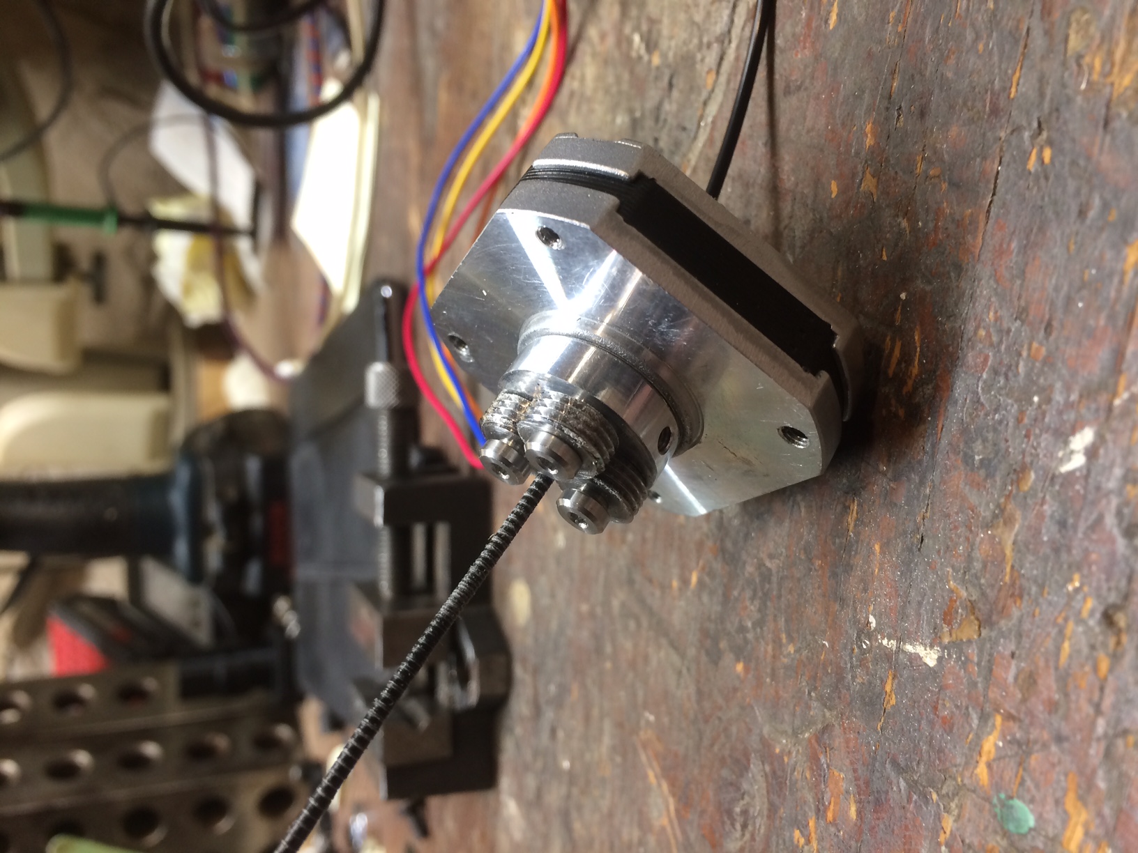
Attached is my latest drive assembly, with printed (non-functional) Archimedes screws. I was hoping to have the real thing (machined steel) from my machine shop this week, but they have larger projects before mine.
|
Re: A Very Different Extruder June 05, 2021 10:55PM |
Registered: 7 years ago Posts: 363 |
Your new carrier looks nice. Regarding the grit, I understand what you are saying, but is that even really necessary in this specific application? polished steel vs polished steel over a length of 1 meter, having a means to register the bearings at a precise point along a linear shaft I understand. But in this case, shouldn't rotary position be enough provided slippage through the bearings is entirely prevented? This would hold particularly true in the case of a direct drive configuration (the primary potential use-case for a design like this) as retraction should be quiet small indeed so any positioning error would be entirely negligible I think. Do my (what feels like logical) conclusions/assumptions not make sense?
Also, I came across a copy of the Fuselab patent and while it wasn't particularly detailed, it seems like they use a similar screw mechanism to your new archimedes approach, however I think they use a ring gear to sync the screws to each other. I'm not sure if they align the screw positions so the threads match though, that part is unclear.
Also, I came across a copy of the Fuselab patent and while it wasn't particularly detailed, it seems like they use a similar screw mechanism to your new archimedes approach, however I think they use a ring gear to sync the screws to each other. I'm not sure if they align the screw positions so the threads match though, that part is unclear.
|
Re: A Very Different Extruder June 06, 2021 05:12AM |
Registered: 8 years ago Posts: 62 |
|
Re: A Very Different Extruder June 06, 2021 07:19AM |
Registered: 7 years ago Posts: 363 |
|
Re: A Very Different Extruder June 06, 2021 12:43PM |
Registered: 8 years ago Posts: 62 |
All that makes a lot of sense: Actively rotating the grooved rollers will avoid the "free" torsional moment of the filament - simple & clever!
A new generation of extrusion systems is born

|
Re: A Very Different Extruder June 07, 2021 05:30PM |
Registered: 4 years ago Posts: 285 |
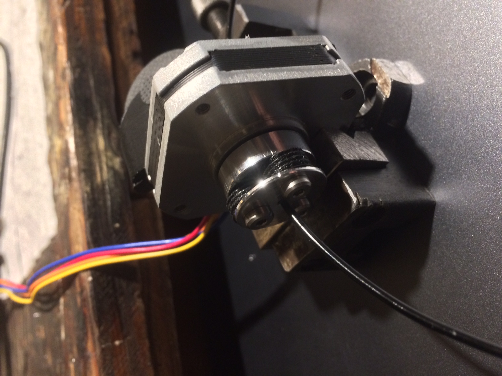
Hopefully, the final path to the final design. My watchmakers lathe doesn't cut threads, so I had a local machine shop thread some steel bar stock so that it was precisely 10mm in diameter, with 28 threads per inch coming to a sharp apex. Normally a thread has a flat apex; these don't. I then bored the bar to 4mm to fit the precision shoulder screws (I didn't bother with ball bearings with this iteration), and sliced off three 4mm thick sections.
While feeding filament, it is not possible to stop the feed without breaking the filament, even with the 11.6mm thick stepper running at 0.3 amps (rated for 1.0 amp). The feed rate is dependent upon the pitch of the threads. Repetitively feeding 100mm and then retracting 100mm is exactly repeatable. The marked filament stops in exactly the same place each time.
This design doesn't need canted bearings or axles; they are perpendicular to the motor shaft, so very easy to machine There is also no spring loading of the threaded rollers, they simply bite into the filament 0.1mm as they roll around it, which also provides the drive force for the rotating threads. You can see the impressed thread pattern in the filament in the attached photo. This design feeds even more slowly than the canted bearings, but again, that is just thread pitch dependent. Even without ball bearings in the threaded rollers, the torque on the filament doesn't seem to be any worse than with the other designs, which makes sense since the threaded rollers are...rolling on the filament and solely driven by contact with it.
I removed the "spider plate" under the screw heads for the photo. The spider plate keeps the screws from bending under load, although it seems to work just fine without the plate.
On to printing!
Edited 3 time(s). Last edit at 06/07/2021 05:45PM by rq3.
|
Re: A Very Different Extruder June 07, 2021 11:08PM |
Registered: 7 years ago Posts: 363 |
|
Re: A Very Different Extruder June 08, 2021 11:20AM |
Registered: 9 years ago Posts: 31 |
Are you sure the "rollers" are... rolling? Based on the grooves in the filament and what appears to be filament dust on the roller threads in your posted image, it looks like your design is gouging rather than pressing the threaded pattern into the plastic. I remain skeptical that pure rolling contact would result in any net axial thrust on the filament.
Of course, in the end, the proof is in the printing, and it is exciting to see your progress. :-)
Of course, in the end, the proof is in the printing, and it is exciting to see your progress. :-)
|
Re: A Very Different Extruder June 08, 2021 03:28PM |
Registered: 7 years ago Posts: 363 |
Quote
NathanaelXYZ
...appears to be filament dust on the roller threads in your posted image...
I noticed that too, which raises potential concerns about possible thread clogging in the future.
I still like the idea of textured friction contact using bearings better, because this new approach requires some custom machining. As mentioned before by someone else, the initial concept posted seemed more readily reprappable and the ease with which I've been able to reproduce the concept is proof of it.

Edit: On that note, my first attempt to 'texture' the bearing surfaces was to just scuff the bearing surface up with some 400 grit sandpaper, this improved the bearing grip quite a bit, but I don't feel like its 'enough' for higher speed printing where back-pressures could potentially build up trying to push plastic through the nozzle. I am going to try something coarser and do some more testing. Eventually I intend to turn the bearing carrier into a gear and drive it using a 50g nema 14 motor with a drive gear attached to the output shaft (don't have access to a lathe capable of putting a 3mm hole into the 5mm motor shaft). I'm uncertain what step-up ratio I want to drive the carrier at. 1:1, 1:2, or 1:3. I may just try each to determine which has a good balance between driving power, precision and max speed.
Edited 2 time(s). Last edit at 06/08/2021 03:37PM by obelisk79.
|
Re: A Very Different Extruder June 09, 2021 06:45PM |
Registered: 4 years ago Posts: 285 |
NathanaelXYZ, you are so right. There IS abrasion. Or was.
A few observations:
I noticed while running the threaded sleeves on non-canted axles, that the sleeves actually travel in the same direction as the filament. Wait. That can't be right. What happened to Newton's laws? If what I am seeing is true, I could epoxy a machine nut into my anus, sword swallow a matching thread rod, keep the rod from spinning with one hand, and spin like a ballerina while levitating. Literally lift myself by my bootstraps!
So I went to Home Depot, got a big machine nut and 3 feet of matching threaded rod, and some epoxy. Then I went home, lured the cat into my shop, and...
Not really. You can't hold the threaded rod with one hand, because then it wouldn't spin relative to the nut. Oh well. So much for visions of reactionless space propulsion, but I'm willing to predict that's an image you won't soon forget. Kind of like Scott Adams opening the kimono while doing jumping jacks in front of your picture window (only Dilbert fans need respond).
Back to reality. The threaded sleeves migrate up the axle in the same direction as the filament because the rotating pitch angle ratio is greater than than speed of the filament. It took a few minutes of thought to decipher that, and I proved it to my self by printing 3 more bearing carriers. One had a cant angle of 5.6 (less than the theoretical pitch angle of 5.7 degrees), one at 5.8 degrees, and one with a combination of the two. In my own head, I think of a rod (the filament) with 28 threads per inch, with a drive nut of either 27 or 29 threads per inch. There's a lot of friction and weird forces involved.
The threaded sleeves do indeed go to the other end of the axle while driving the filament in the same direction, depending upon their angle, which partially explains the anomalously slow feed and scuffing of the filament if the axles are parallel to the motor shaft. The threaded sleeves are grinding as much as they are feeding. More below.
With an axle cant exactly equal to the pitch angle, there is (theoretically) zero axial force on the sleeves, and their rotation goes purely into driving the filament. That angle is 5.71 degrees for a 1mm pitch on a 10mm major diameter (I don't use pitch diameter here, because the filament doesn't get that deep).
Another factor that contributes to the observations of NathanaelXYZ (thank you, Sir!) is that I had the axles canted the wrong way! The threads were trying to feed in one direction, and the cant was trying to oppose that (as if I were still using smooth drive bearings). I had to think through the fact that the threaded rollers are rotating in a direction opposite to the motor shaft.
One final oddity. My original design had the ball bearings carefully pre-loaded and constrained axially. With the threaded sleeves, they must be allowed to "float" axially at least one thread pitch. Otherwise, when the filament is introduced, there is a very high chance that the threaded rollers will introduce 1, 2, or 3 "starts" in the filament threads. Anything more than one means that a roller may be (likely will be) shaving material from the filament at the next rotation.
Everything makes sense, at least in my own warped mind. Torque on the filament is even less (I've dropped the stepper current to 0.2 amps from 0.3), repeatability is as good or better than before, and the filament feed rate is much higher because the geometry isn't fighting itself. At a first guess, I estimate the stepper rate will drop by an order of magnitude (from 11,100 to about 1000), which is more sane and in line with the math.
Attached is the FreeCad file for the latest and greatest bearing carrier, along with the Cura sliced STL. Printed in PLA at 0.05mm layer height, 100% concentric infill, with ArcWelder plug-in.
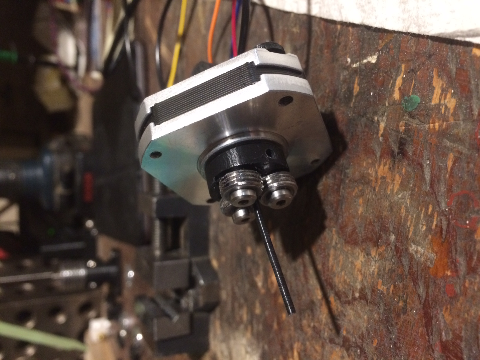
Also a shot of what I hope is close to the last iteration, given all that I have learned. So far. Two steps forward, one step back.
On to printing, again.
Edited 7 time(s). Last edit at 06/09/2021 09:49PM by rq3.
A few observations:
I noticed while running the threaded sleeves on non-canted axles, that the sleeves actually travel in the same direction as the filament. Wait. That can't be right. What happened to Newton's laws? If what I am seeing is true, I could epoxy a machine nut into my anus, sword swallow a matching thread rod, keep the rod from spinning with one hand, and spin like a ballerina while levitating. Literally lift myself by my bootstraps!
So I went to Home Depot, got a big machine nut and 3 feet of matching threaded rod, and some epoxy. Then I went home, lured the cat into my shop, and...
Not really. You can't hold the threaded rod with one hand, because then it wouldn't spin relative to the nut. Oh well. So much for visions of reactionless space propulsion, but I'm willing to predict that's an image you won't soon forget. Kind of like Scott Adams opening the kimono while doing jumping jacks in front of your picture window (only Dilbert fans need respond).
Back to reality. The threaded sleeves migrate up the axle in the same direction as the filament because the rotating pitch angle ratio is greater than than speed of the filament. It took a few minutes of thought to decipher that, and I proved it to my self by printing 3 more bearing carriers. One had a cant angle of 5.6 (less than the theoretical pitch angle of 5.7 degrees), one at 5.8 degrees, and one with a combination of the two. In my own head, I think of a rod (the filament) with 28 threads per inch, with a drive nut of either 27 or 29 threads per inch. There's a lot of friction and weird forces involved.
The threaded sleeves do indeed go to the other end of the axle while driving the filament in the same direction, depending upon their angle, which partially explains the anomalously slow feed and scuffing of the filament if the axles are parallel to the motor shaft. The threaded sleeves are grinding as much as they are feeding. More below.
With an axle cant exactly equal to the pitch angle, there is (theoretically) zero axial force on the sleeves, and their rotation goes purely into driving the filament. That angle is 5.71 degrees for a 1mm pitch on a 10mm major diameter (I don't use pitch diameter here, because the filament doesn't get that deep).
Another factor that contributes to the observations of NathanaelXYZ (thank you, Sir!) is that I had the axles canted the wrong way! The threads were trying to feed in one direction, and the cant was trying to oppose that (as if I were still using smooth drive bearings). I had to think through the fact that the threaded rollers are rotating in a direction opposite to the motor shaft.
One final oddity. My original design had the ball bearings carefully pre-loaded and constrained axially. With the threaded sleeves, they must be allowed to "float" axially at least one thread pitch. Otherwise, when the filament is introduced, there is a very high chance that the threaded rollers will introduce 1, 2, or 3 "starts" in the filament threads. Anything more than one means that a roller may be (likely will be) shaving material from the filament at the next rotation.
Everything makes sense, at least in my own warped mind. Torque on the filament is even less (I've dropped the stepper current to 0.2 amps from 0.3), repeatability is as good or better than before, and the filament feed rate is much higher because the geometry isn't fighting itself. At a first guess, I estimate the stepper rate will drop by an order of magnitude (from 11,100 to about 1000), which is more sane and in line with the math.
Attached is the FreeCad file for the latest and greatest bearing carrier, along with the Cura sliced STL. Printed in PLA at 0.05mm layer height, 100% concentric infill, with ArcWelder plug-in.
Also a shot of what I hope is close to the last iteration, given all that I have learned. So far. Two steps forward, one step back.
On to printing, again.
Edited 7 time(s). Last edit at 06/09/2021 09:49PM by rq3.
|
Re: A Very Different Extruder June 09, 2021 07:55PM |
Registered: 7 years ago Posts: 363 |
|
Re: A Very Different Extruder June 09, 2021 08:35PM |
Registered: 4 years ago Posts: 285 |
Quote
obelisk79
Thanks for the update, mind attaching a photo or screenshot of the new design? I'm in the Navy and on a ship in the middle of the ocean. Due to network restrictions, I have no current means to transfer freecad files to my personal computer from the network to look at what you've done.
obelisk79, thank you for all that you do. I have edited my previous post with a shot of the latest and greatest. I only wish that there was enough bandwidth on RepRap.org to post short videos, but 800K doesn't quite cut it.
Be well.
|
Re: A Very Different Extruder June 10, 2021 12:50AM |
Admin Registered: 16 years ago Posts: 13,884 |
... for the videos -- I'm uploading my videos to youtube and posting the link ...
Viktor
--------
Aufruf zum Projekt "Müll-freie Meere" - [reprap.org] -- Deutsche Facebook-Gruppe - [www.facebook.com]
Call for the project "garbage-free seas" - [reprap.org]
Viktor
--------
Aufruf zum Projekt "Müll-freie Meere" - [reprap.org] -- Deutsche Facebook-Gruppe - [www.facebook.com]
Call for the project "garbage-free seas" - [reprap.org]
|
Re: A Very Different Extruder June 10, 2021 06:21PM |
Registered: 4 years ago Posts: 285 |
Quote
VDX
... for the videos -- I'm uploading my videos to youtube and posting the link ...
It's been years since I posted on YouTube, and the process wasn't fun. But here you go:
[www.youtube.com]
|
Re: A Very Different Extruder June 20, 2021 11:08AM |
Registered: 11 years ago Posts: 5,780 |
I just found this post - my browser hadn't indicated any new posts for a couple years.
I worked on something similar to this, but not nearly as elegant, a few years ago using cheap plastic gears and counter rotating nuts. That was back when really crappy hot-ends and extruders were all that was available. My design worked for 3 mm filament (I used 6-32 nuts). I thought that the counter rotation would prevent the filament from twisting, and it sort-of worked, but the filament liked to twist when I reversed the drive. I put it on a printer and it worked well, providing extremely smooth extrusion. The biggest problems were that the nuts would bite different diameter filaments harder or softer and the twisting would get worse with the harder bite. Retraction didn't work very well. The drive could apply an enormous amount of force to the filament, so it would be really hard to make it jam in the hot end. It seemed like you could almost extrude cold filament through the nozzle with it.
[vimeo.com]
[vimeo.com]
[vimeo.com]
[vimeo.com]
[vimeo.com]
Have you tried your design on a printer yet?
Ultra MegaMax Dominator 3D printer: [drmrehorst.blogspot.com]
|
Re: A Very Different Extruder June 20, 2021 05:26PM |
Registered: 4 years ago Posts: 285 |
I really like that! Where did you find left hand threaded nuts? Yes, I've printed successfully (see the calibration cube on the previous page), and kick myself for not having a shot of the installed unit. Soon. I've been playing with various thread pitches and skew angles, and have found that I can make the threaded rollers from hardware store bolts, chucked in my lathe and rotated very slowly while I use a triangular jewelers file to "chase" the threads and make them sharp. As I've mentioned before, I'm not using ball bearings anymore. The threaded rollers ride directly on the shoulder screw axles, with 3 in 1 oil lubrication. Much easier during repetitive protyping and testing!
I've tried various filaments from various manufacturers, and they all seem to track the same. Perhaps the filament diameter tolerances are better these days, or, on the the fact that the threads are rolling around the filament, embedding only as deep or shallow as needed, based on the varying filament diameter. The torque on the filament is very light (equal to the bearing drag), if I keep the "bite" reasonable. About 0.1mm at each roller seems to be about optimum. It doesn't sound like much, but I cannot pull the filament out without breaking it. I'm using a 1 amp rated NEMA 17 pancake stepper, and only driving it at 0.2 amp. I suspect a NEMA 14 or even 11 would work just as well, and be even lighter.
Like your design, and for the same reason, the extrusion force is ludicrous due to the mechanical advantage of the thread's inclined plane.
The downside is that it can only be loaded (or unloaded) with the rollers rotating, and unless I monkey with my stepper drivers, I need silly steps per millimeter, like 11,000. But that's thread pitch, axle skew, motor, and driver microstep dependent. A lot of variables to play with!
Edited 1 time(s). Last edit at 06/20/2021 05:53PM by rq3.
|
Re: A Very Different Extruder June 20, 2021 06:33PM |
Registered: 11 years ago Posts: 5,780 |
I made the left hand threaded nut using a small piece of steel and a left hand threaded tap. The nuts were soldered to 5mm diameter brass tubes that fit tightly in the gears and into bearings that were embedded in the printed ABS housing. This blog post has some pictures of the snakebite extruder showing the bearings, etc. The housing is actually three printed parts with bosses to ensure alignment when assembling them. There were two ball bearings for each of the rotating brass tubes. I bought the set of gears for a dollar or two, so the most expensive part was the left hand tap at maybe $5. I first got an idea for using a nut when I was fooling around and noticed that I could thread a nut onto a piece of 3mm filament. Then I thought about how to drive it, then about how to deal with it trying to twist the filament and that's where I ended up with counter rotating nuts. If one nut gripped the filament harder than the other it tried to twist the filament. I thought about installing a wheel to prevent the twisting, but ultimately gave up on the whole thing as impractical when I found too much variability in 3 mm filament diameter and in inconsistencies in the diameter of the holes and depth of threads in nuts (which could be fixed by making my own nuts), and problems with retraction- similar to problems with retraction with bowden tube extruders, but inconsistent because of the whole filament/nut hole/thread depth diameter problems. I thought about threading the inside of a collet so I could make the size adjustable to compensate for filament diameter, but by then I had lost interest in it.
Your system seems much more practical. Loading and unloading is easy enough- just tell it to extrude or retract while the hot end is heated. That's standard operating procedure for Prusa I3s, so it isn't really anything too weird for people to figure out or get used to.
Here's the first test print- clearly there are retraction problems:
Here's another print with weird loops that show up in strange places:
Edited 1 time(s). Last edit at 06/20/2021 06:39PM by the_digital_dentist.
Ultra MegaMax Dominator 3D printer: [drmrehorst.blogspot.com]
Your system seems much more practical. Loading and unloading is easy enough- just tell it to extrude or retract while the hot end is heated. That's standard operating procedure for Prusa I3s, so it isn't really anything too weird for people to figure out or get used to.
Here's the first test print- clearly there are retraction problems:

Here's another print with weird loops that show up in strange places:

Edited 1 time(s). Last edit at 06/20/2021 06:39PM by the_digital_dentist.
Ultra MegaMax Dominator 3D printer: [drmrehorst.blogspot.com]
|
Some Final (?) Notes June 27, 2021 06:17PM |
Registered: 4 years ago Posts: 285 |
This extruder geometry is definitely functional, as I have actually printed with it. Having said that, and dozens of iterations later, a few notes:
None of the stepper motors that I have use hardened shafts, which makes sense since they expect a grub screw to be used to lock any applied device (pulley, whatever) to the shaft. And they all have centering countersinks in the shaft ends produced during manufacture. All of the shafts that I experimerimented with were easily drilled in a drill press, with the shaft clamped in a V groove machinists vice. If you want a nice, polished, bore, drill to #48 bit, apply a drop of high pressure lubricant to the hole (like STP), and press a 5/64" diameter Tungsten Carbide ball down the hole with a 1/16" drill rod using the drill press (not rotating) as an arbor press. I use this technique to apply a ballized finish to the interior of my experimental heat breaks. It leaves a mirror finished interior bore, and in the case of heatbreaks, slightly expands the tubing to provide an even better force fit with the hot and cold ends.
While a threaded roller on a straight (non-skewed) axle does work, the feed rate is very slow. My initial design needed about 11,000 steps per millimeter, which was untenable, particularly for high speed (acceleration) retraction. Skewing, or canting, the axle solves that issue.
With a skewed axle, all of the bearing surface treatments I have tried did not last very long. The contact is a straight line on the periphery of the bearing, and shot peening, grinding, grit coating, etc., does not provide a repeatable experience, at least not within the 1% I would need to see before investing in plated diamond grit.
I also machined single point rollers to provide skewed contact with the filament. While this worked well, it involved machining of unique parts. I'm not necessarily against that, but a simpler "hardware store" approach is more appealing.
So. The mechanics (physics, math?) get interesting. A 10mm diameter bolt with 1.25mm pitch threads has a pitch diameter of 9.188mm. It needs roughly 5.7 revolutions aound a 1.75mm diameter filament to compete a revolution. The pitch angle of the threaded bolt is 2.48 degrees, so a skew angle of about 14.2 degrees should get each thread re-engaged with each groove at the proper time. And it does, though I settled on a design skew of 15 degrees (call me a fool for 0.8 degrees). Drive torque is even lower, repeatability and accuracy is acceptable (to me), and the trick is to use ONE threaded drive roller, and TWO smooth filament contact rollers. While this reduces the drive engagement with the filament, I cannot pull the filament out of the drive without stripping the axle bolt threads (>30 pounds force). The bearing carrier is PLA, printed at 0.05mm layer height, 100% concentric infill (FreeCad file attached, STL is too large).
One interesting artifact of this approach is that, as the filament diameter varies from ideal, the contact point with the drive roller varies more or less in regard to the pitch diameter of the drive threads. In other words, it tends to auto-correct for filament diameter variation. The smaller the filament, the faster it extrudes, because the drive roller diameter becomes effectively larger (within obvious limits).
I have yet more bearings on order, which are due to arrive next week. Currently, my threaded roller is riding directly on the precision shoulder screw as an axle. Not good. I'm going to modify a threaded roller to accept two flanged bearings before re-installing this animal on my delta printer again, and do some more test printing. Steps per millimeter is down from a ludicrous 11,100 to a high but reasonable 2285 (0.9 degree stepper, 16 microsteps).
Edited 5 time(s). Last edit at 06/27/2021 10:06PM by rq3.
|
Final Prototype-time for more printing June 29, 2021 02:56PM |
Registered: 4 years ago Posts: 285 |
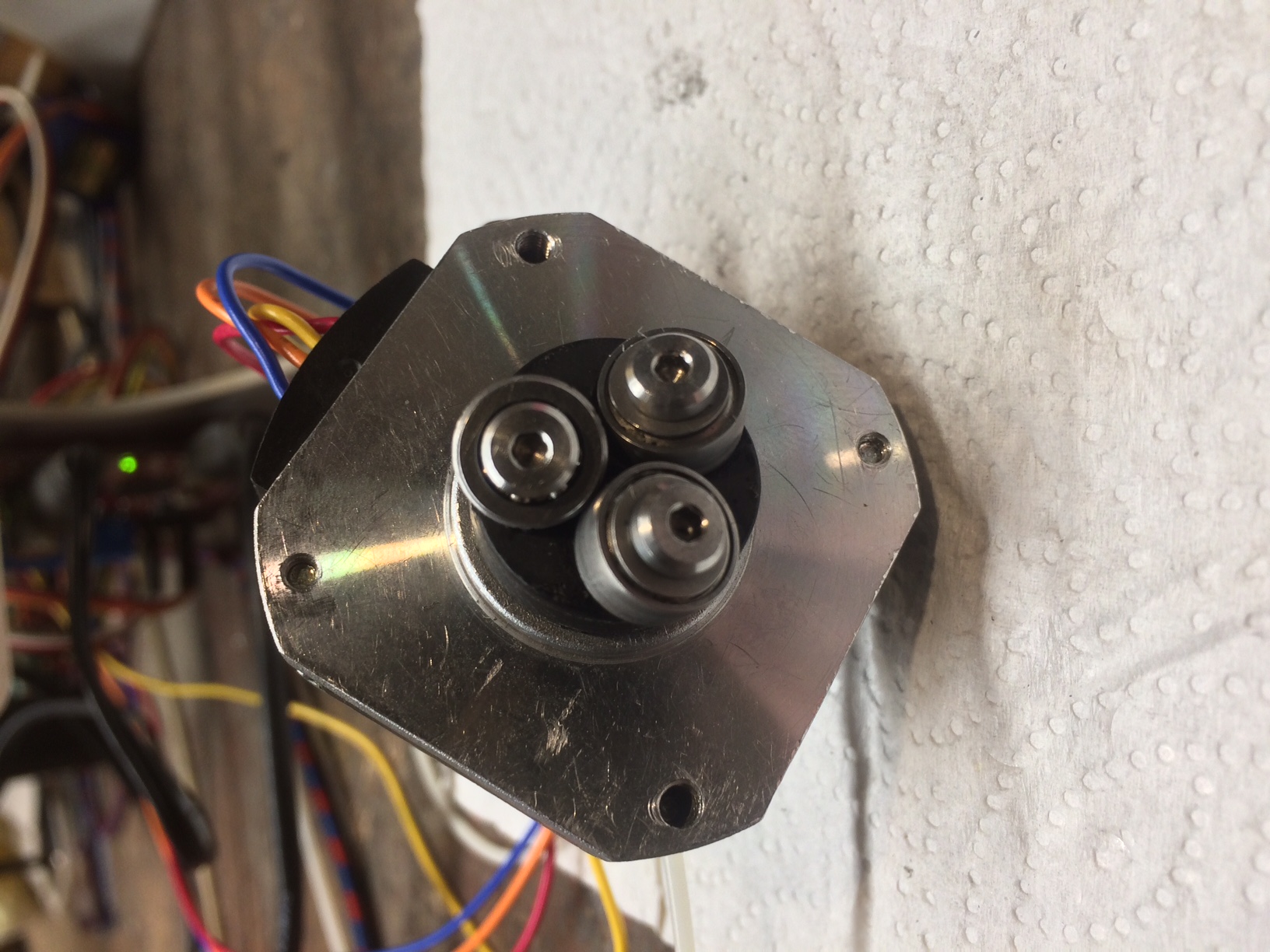
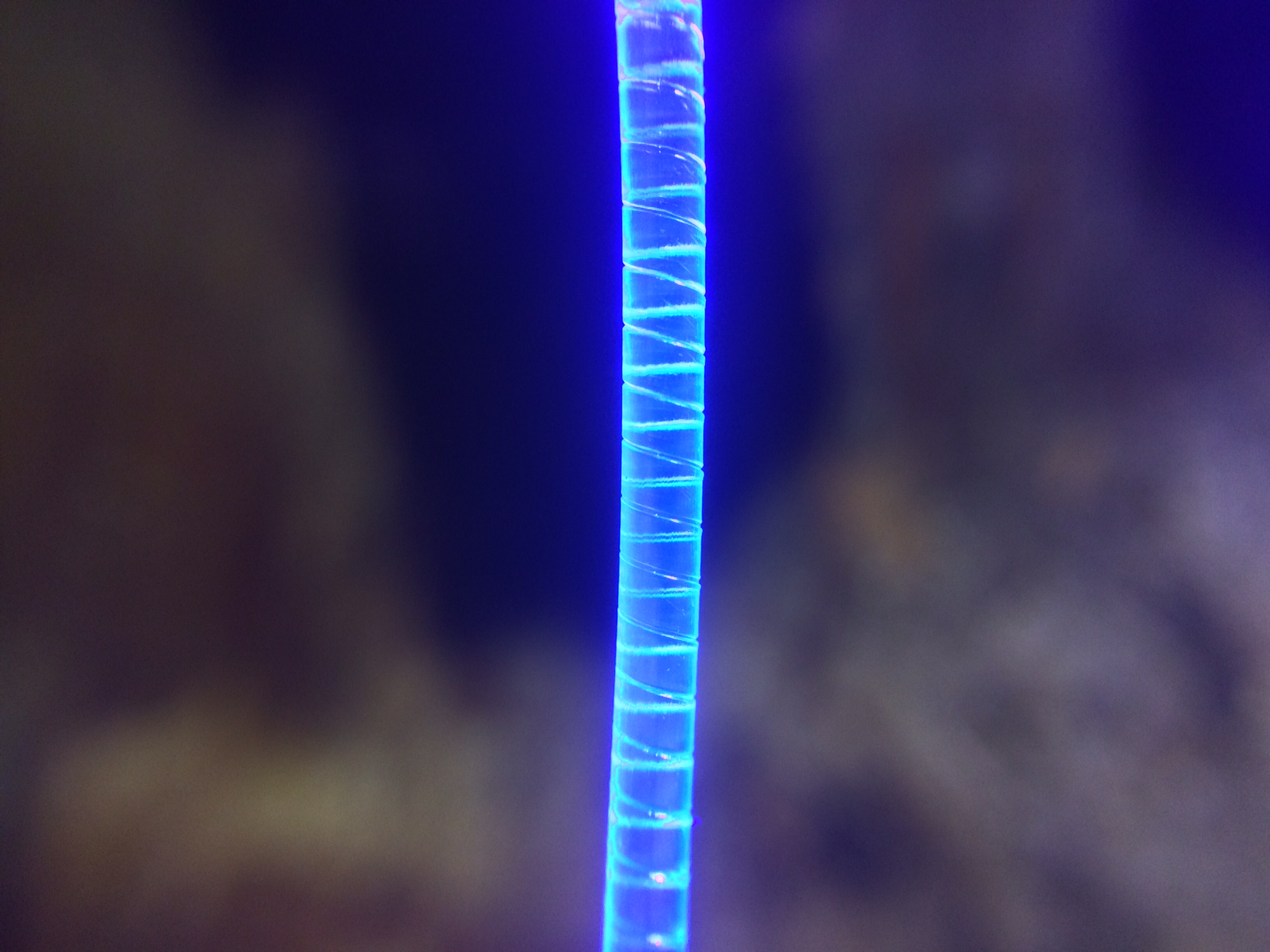
Adding two miniature flanged ball bearings to the threaded drive roller drastically reduces the filament torsion and the motor current. I'm sure a NEMA 14 or even 11 motor would work. No real surprise here. These two bearings are open (no seals or shields) so I can watch them in action (you can just make out a few of the balls under the head of the screw). So the only "custom" part is a short (3.85mm) length of 10mmx1 bolt, bored to 8mm.
Also a macro shot of clear PETG filament fluorescing under UV illumination. If you zoom in you can make out the 0.1mm deep scores from the drive roller.
Edited 3 time(s). Last edit at 07/01/2021 01:01PM by rq3.
Also a macro shot of clear PETG filament fluorescing under UV illumination. If you zoom in you can make out the 0.1mm deep scores from the drive roller.
Edited 3 time(s). Last edit at 07/01/2021 01:01PM by rq3.
|
Re: A Very Different Extruder July 18, 2021 10:21PM |
Registered: 10 years ago Posts: 239 |
|
Re: A Very Different Extruder July 19, 2021 01:02AM |
Registered: 7 years ago Posts: 363 |


Sorry, only registered users may post in this forum.