A Very Different Extruder
Posted by rq3
|
Re: A Very Different Extruder July 19, 2021 01:55AM |
Admin Registered: 16 years ago Posts: 13,884 |
... I've tested with some "micro-gearing/teething" with screw-heads for better friction -- it works pretty well with a fiberlaser and the edges/teeth are harder than the not heated surface 
Viktor
--------
Aufruf zum Projekt "Müll-freie Meere" - [reprap.org] -- Deutsche Facebook-Gruppe - [www.facebook.com]
Call for the project "garbage-free seas" - [reprap.org]


Viktor
--------
Aufruf zum Projekt "Müll-freie Meere" - [reprap.org] -- Deutsche Facebook-Gruppe - [www.facebook.com]
Call for the project "garbage-free seas" - [reprap.org]
|
Re: A Very Different Extruder July 19, 2021 03:05PM |
Registered: 11 years ago Posts: 5,780 |
rq3: This looks quite similar to your extruder: [www.youtube.com]
Ultra MegaMax Dominator 3D printer: [drmrehorst.blogspot.com]
Ultra MegaMax Dominator 3D printer: [drmrehorst.blogspot.com]
|
Re: A Very Different Extruder July 19, 2021 04:33PM |
Admin Registered: 16 years ago Posts: 13,884 |
... there where/are some other versions too around -- it's an older principle, patented 1952 by a Mr. Uhing for moving spool-heads on horizontal axes ... but could be used for other tasks too 
Especially this "scewed tap-rollers" were sometimes used for special high precision CNC-applications ...
Viktor
--------
Aufruf zum Projekt "Müll-freie Meere" - [reprap.org] -- Deutsche Facebook-Gruppe - [www.facebook.com]
Call for the project "garbage-free seas" - [reprap.org]
Especially this "scewed tap-rollers" were sometimes used for special high precision CNC-applications ...
Viktor
--------
Aufruf zum Projekt "Müll-freie Meere" - [reprap.org] -- Deutsche Facebook-Gruppe - [www.facebook.com]
Call for the project "garbage-free seas" - [reprap.org]
|
Re: A Very Different Extruder July 19, 2021 09:21PM |
Registered: 4 years ago Posts: 285 |
Yes, mentioned and linked to earlier in this thread. However, my drive rollers are not gear syncronized. Completely different design, unless we all want to give credit to Archimedes. And I do.
Generally there is rarely anything new under the sun, which is part of what makes the current patent system unworkable. Different topic.
|
Re: A Very Different Extruder July 19, 2021 09:32PM |
Registered: 4 years ago Posts: 285 |
Quote
VDX
... there where/are some other versions too around -- it's an older principle, patented 1952 by a Mr. Uhing for moving spool-heads on horizontal axes ... but could be used for other tasks too
Especially this "scewed tap-rollers" were sometimes used for special high precision CNC-applications ...
I'm not sure what you mean by "screwed tap-rollers". The Rohlix linear drive is commercially available, but not particularly accurate or repeatable (see the very beginning of this thread).
Rolled threads are very common industrially, especially external. Some web searching will yield a plethora of data on the design of the tools used, and the criticality of their angles.
It's a good place to start if you want to repeat or improve upon my effort.
|
Re: A Very Different Extruder July 20, 2021 03:07AM |
Registered: 7 years ago Posts: 11 |
I think VDX is reffering to this patent: https://patents.google.com/patent/US2940322A/ which, as far as I'm aware, is the oldest recording of using canted bearing riding on a smooth rod to propel the bearing assembly (or rod, whichever way you look at it).
https://groups.google.com/g/3dp-ideas/c/YGFYajwyVrc is a google group discussing a similar extruder to the Fuselab 3D one, though predating their patent with a few years.
There is another execution of the idea here: https://www.reddit.com/r/3Dprinting/comments/nowr6v/i_made_a_silly_extruder_works_like_a_charm/.
By the way; hollow tubes with an outside thread are called "nipples" (though if you search for them, add "threaded"). Commonly available for lampfittings or as a plumbing connector. I've seen them with diameters ranging from 10mm to 1", in materials from stainless to brass.
What made you switch from the treaded sleeve to a single, sharpened concentric race? Ease of manufacturing? Is there a performance difference? Intuitively I'd excpect a lower gripping force, but also less grinding, compared to the threaded sleeve.
|
Re: A Very Different Extruder July 20, 2021 10:11AM |
Registered: 7 years ago Posts: 363 |
Quote
Skrogh
What made you switch from the treaded sleeve to a single, sharpened concentric race? Ease of manufacturing? Is there a performance difference? Intuitively I'd excpect a lower gripping force, but also less grinding, compared to the threaded sleeve.
I think rq3 mentioned it in the other thread, but if I understand correctly, their concern was over repeatability. By using the concentric edge it allowed for greater repeatability and accuracy as it would always ride the resulting groove in the filament during retraction/de-retraction. You could probably get improved grip (if its even necessary in this application) by stacking additional races. However you'd have to consider implementation carefully. Do you space it to cut 2 helices into the filament or attempt to accurately space/machine them so they ride the same helix. For simplicity sake, I would assume 2 helices would be easier and potentially superior for grip.
|
Re: A Very Different Extruder July 24, 2021 08:08AM |
Registered: 3 years ago Posts: 92 |
Brilliant design! Might actually be light enough to convert my SCARA printer to direct drive. I have a 50 gram round NEMA14 I could use. And TMC2209 drivers, so I can adjust the microsteps to whatever works best. I'd prefer to use non-canted axles so I can make the carrier out of aluminum, but would all three rollers need to be threaded then since the filament would be getting dragged axially across the smooth rollers, or do you think the friction would be negligible? It would be nice not to have to worry about the issue of cutting multiple thread starts into the filament.
|
Re: A Very Different Extruder July 24, 2021 05:34PM |
Registered: 4 years ago Posts: 285 |
Quote
dekutree64
Brilliant design! Might actually be light enough to convert my SCARA printer to direct drive. I have a 50 gram round NEMA14 I could use. And TMC2209 drivers, so I can adjust the microsteps to whatever works best. I'd prefer to use non-canted axles so I can make the carrier out of aluminum, but would all three rollers need to be threaded then since the filament would be getting dragged axially across the smooth rollers, or do you think the friction would be negligible? It would be nice not to have to worry about the issue of cutting multiple thread starts into the filament.
From my experiments, non-canted axles will work with one threaded drive roller. BUT, you will have to turn off all micro-stepping for the motor to get reasonable stepping rates. Use the largest pitch thread that you can fit onto the drive roller. The friction of the other two support rollers is negligable. I did machine an aluminum carrier with canted axles, and it wasn't too tedious. The worst part was feeding the canted 11mm end mill into the aluminum. It's engaging at the edge of the cutter, and wants to chatter pretty ferociously. Go slow. Once the end mill flat spot is done, you're all set to drill the hole for the axle threads, since you are going into a flat surface, and the mill is already properly located.
Edited 2 time(s). Last edit at 07/24/2021 09:30PM by rq3.
|
Re: A Very Different Extruder July 25, 2021 07:33AM |
Registered: 3 years ago Posts: 92 |
Thanks, that confirms my thoughts. I probably could make a fixture to mill/drill the tilted axes on my 3DOF mini-mill, but I'd actually prefer the higher effective gear ratio since it should allow using even lighter motors. There is one seller for pancake NEMA11 on ebay, though it costs $25 with shipping, and has a 4mm shaft, which doesn't leave much meat after drilling a 2mm hole.
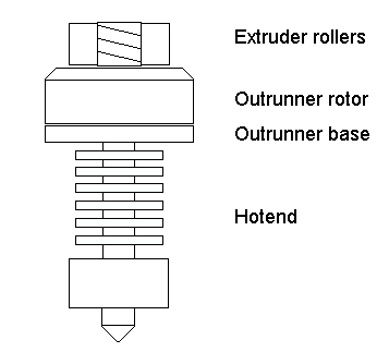
I'm also toying around with the idea of making one of these based on a small outrunner instead of NEMA stepper. I'm fairly sure it would be possible to rewind one as a stepper as long as it has an even number of stator arms. Resolution would be very coarse (for example the common 12 stator arms/14 rotor magnets would be 28 steps per revolution, or 12.86 degrees per step), so probably will need microstepping even with straight axles (if my calculations are correct, that would give 128 full steps per mm with 1.75mm filament and 10mm rollers with 1.25mm thread pitch). Both the roller carrier and hollow mounting structure between the motor and hotend could potentially be eliminated. But there's nowhere to mount the anti-torsion wheel without an equally heavy structure to reach around the motor, so it may be a no-go. Depends on if I can come up with some other anti-torsion technique.
Edited 1 time(s). Last edit at 07/25/2021 07:46AM by dekutree64.
|
Re: A Very Different Extruder July 25, 2021 04:25PM |
Registered: 4 years ago Posts: 285 |
Quote
dekutree64
Thanks, that confirms my thoughts. I probably could make a fixture to mill/drill the tilted axes on my 3DOF mini-mill, but I'd actually prefer the higher effective gear ratio since it should allow using even lighter motors. There is one seller for pancake NEMA11 on ebay, though it costs $25 with shipping, and has a 4mm shaft, which doesn't leave much meat after drilling a 2mm hole.
I'm also toying around with the idea of making one of these based on a small outrunner instead of NEMA stepper. I'm fairly sure it would be possible to rewind one as a stepper as long as it has an even number of stator arms. Resolution would be very coarse (for example the common 12 stator arms/14 rotor magnets would be 28 steps per revolution, or 12.86 degrees per step), so probably will need microstepping even with straight axles (if my calculations are correct, that would give 128 full steps per mm with 1.75mm filament and 10mm rollers with 1.25mm thread pitch). Both the roller carrier and hollow mounting structure between the motor and hotend could potentially be eliminated. But there's nowhere to mount the anti-torsion wheel without an equally heavy structure to reach around the motor, so it may be a no-go. Depends on if I can come up with some other anti-torsion technique.
You are right, there are several NEMA 11 pancake steppers available that have appropriate torque curves. They mass about 28 grams, which would make the entire assembly weigh in at about 60 grams. They have 3 mm shaft diameters, which doesn't concern me. A 0.5mm shaft wall would be more than enough. And yes, they are not cheap, but prototypes rarely are. I estimate I'm about $700 into this project so far, and I'm in the process of placing an order for the parts for the final, final, no really, the final design.
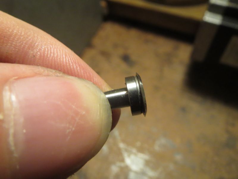
One hopefully final note. I have settled on two plain ABEC-5 shielded bearings as pressure rollers, and one flanged ABEC-5 shielded bearing for the drive roller. The flange will be ground to provide the required hardened knife edge, as I mentioned before. The note is that if the flange isn't ground symetrically, the filament extrusion and retraction will be different (which makes sense if you think about the filament contact geometry).
A final, final, no really, final note. It is possible for the drive roller to not roll at all, but just cut into the filament. This gives the fastest and most repeatable extrusion and retraction, but unless the knife edge is fabricated from boron nitride or zirconia, it will only last a few hours. I estimate I've run about 3 spools of PLA, ABS, and PETG through the rotating sharpened flange so far with no sign of wear, though the filament feed rate is reduced by about 20% versus a fixed knife edge.
Edited 1 time(s). Last edit at 07/25/2021 04:33PM by rq3.
|
Very Different Extruder Bill of Materials July 26, 2021 07:04PM |
Registered: 4 years ago Posts: 285 |
Attached is the Bill of Materials for the Very Different Extruder (VDE-100), or SchnekenStruder. These are all common industrial parts, and require no machining with the exception of:
1) The Belleville washers act as preload springs for the bearings, and need to be stacked together, spun in a lathe, drill press, or a drill mounted in a vise, and ground with a dremel tool abrasive disc to an outside diameter of about 9mm to ensure clearance for the filament.
2) The drive bearing needs the same treatment so that its flange is ground to a symmetrical knife edge 10mm in diameter.
Note that I have increased all of the bearing axle diameters from 4mm to 5mm, so that I could use commonly available shielded bearings through out the design, and to stiffen the bending moment of the axles and their screw threads. I spent a great deal of time selecting parts so that the drive and pressure rollers are vertically aligned within 0.1mm (0.004"), inclusive of worst case part dimension tolerances. The bearing, washer, and spacer stack sequence is critical. It only goes together one way!
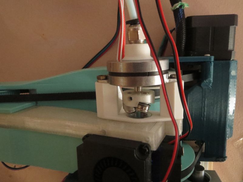
One of the issues with this entire design was that, while very easy to load (it just inhales the filament), it was a bear to unload. Originally I had the motor and drive assembly screwed to the groove mount adapter with 2 screws, which also fastened the anti-torque housing. I have changed to using rare-earth magnets implanted with epoxy in the groove mount adapter and the motor itself. For a filament change, or even an "atomic pull" for a clogged nozzle, I just twist the motor and drive assembly 45 degrees to unlock it from the groove mount adapter. It's then a simple matter to remove the whole thing, with the offending filament. The twist to unlock is required. It is VERY difficult to un-mate the magnets with a straight pull.
The magnets don't affect the motor at all, but may affect nearby sensors. This is not a problem for me as my nozzle contact sensor is a single under-bed piezo unit (previously described).
Have fun!
Edited 1 time(s). Last edit at 07/26/2021 07:09PM by rq3.
1) The Belleville washers act as preload springs for the bearings, and need to be stacked together, spun in a lathe, drill press, or a drill mounted in a vise, and ground with a dremel tool abrasive disc to an outside diameter of about 9mm to ensure clearance for the filament.
2) The drive bearing needs the same treatment so that its flange is ground to a symmetrical knife edge 10mm in diameter.
Note that I have increased all of the bearing axle diameters from 4mm to 5mm, so that I could use commonly available shielded bearings through out the design, and to stiffen the bending moment of the axles and their screw threads. I spent a great deal of time selecting parts so that the drive and pressure rollers are vertically aligned within 0.1mm (0.004"), inclusive of worst case part dimension tolerances. The bearing, washer, and spacer stack sequence is critical. It only goes together one way!
One of the issues with this entire design was that, while very easy to load (it just inhales the filament), it was a bear to unload. Originally I had the motor and drive assembly screwed to the groove mount adapter with 2 screws, which also fastened the anti-torque housing. I have changed to using rare-earth magnets implanted with epoxy in the groove mount adapter and the motor itself. For a filament change, or even an "atomic pull" for a clogged nozzle, I just twist the motor and drive assembly 45 degrees to unlock it from the groove mount adapter. It's then a simple matter to remove the whole thing, with the offending filament. The twist to unlock is required. It is VERY difficult to un-mate the magnets with a straight pull.
The magnets don't affect the motor at all, but may affect nearby sensors. This is not a problem for me as my nozzle contact sensor is a single under-bed piezo unit (previously described).
Have fun!
Edited 1 time(s). Last edit at 07/26/2021 07:09PM by rq3.
|
Re: A Very Different Extruder July 27, 2021 08:58PM |
Registered: 3 years ago Posts: 92 |
Thank you! That ought to save me a few trials and errors. But I also now see where all your money went 
We should be able to eliminate the expensive shoulder screws by machining the posts as part of the carrier and using short M3 screws to hold the rollers on. Also can leave a little ledge at the bottom to replace the shims. Of course this will mean that only people with CNC milling capability can make them, but for larger production runs the carrier will probably be machined regardless.
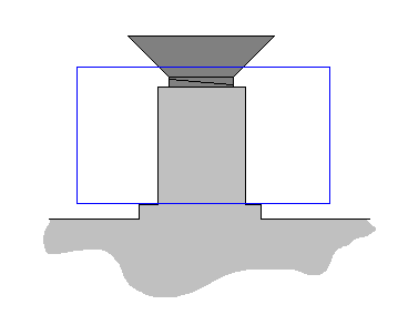
I don't think the belleville is necessary either with the machined posts. They can be made slightly shorter than the bearings, and use a countersunk screw to pinch the roller with some thread to spare. I've attached a drawing showing my envisioned post with ledge at the bottom to provide clearance, and screw with a bit of thread to spare at the top. The see-through blue rectangle represents the bearing.
For unloading, have you tried running it backward 15mm or so, waiting for the filament to cool, and then running some more? The previously-melted filament end may be too lumpy and jam, but may make it through. Especially if it's still a little warm and soft. The magnetic detachment system is certainly more reliable, but also adds to the cost.
EDIT: I had a second drawing attached before, but realized it made no sense.
Edited 1 time(s). Last edit at 07/27/2021 10:00PM by dekutree64.
We should be able to eliminate the expensive shoulder screws by machining the posts as part of the carrier and using short M3 screws to hold the rollers on. Also can leave a little ledge at the bottom to replace the shims. Of course this will mean that only people with CNC milling capability can make them, but for larger production runs the carrier will probably be machined regardless.
I don't think the belleville is necessary either with the machined posts. They can be made slightly shorter than the bearings, and use a countersunk screw to pinch the roller with some thread to spare. I've attached a drawing showing my envisioned post with ledge at the bottom to provide clearance, and screw with a bit of thread to spare at the top. The see-through blue rectangle represents the bearing.
For unloading, have you tried running it backward 15mm or so, waiting for the filament to cool, and then running some more? The previously-melted filament end may be too lumpy and jam, but may make it through. Especially if it's still a little warm and soft. The magnetic detachment system is certainly more reliable, but also adds to the cost.
EDIT: I had a second drawing attached before, but realized it made no sense.
Edited 1 time(s). Last edit at 07/27/2021 10:00PM by dekutree64.
|
Re: A Very Different Extruder July 28, 2021 07:58AM |
Registered: 3 years ago Posts: 92 |
I've decided to go with the canted axle/sharpened bearing flange approach. I'm not sure my mill could handle boring out a 10mm steel screw, nor do I have an easy way to get it centered and vertical under the spindle, so I'm going to have to make some new fixturing regardless. And the bearing should be sharper and longer lasting.
I'm using a 4x8x3mm flange bearing because it's what I have on hand (along with a couple of 4x9x4mm without flange). And I think the 9.2mm flange diameter is good, because it gives exactly 0.1mm "extra" radius for penetration into the filament compared to the two idlers. It also makes grinding easier since you can just go until the edge is sharp, rather than having to reduce the diameter by a precise amount.
I made a 30 degree holder for my trusty DMT Dia-sharp stones out of a scrap of 2x4, with a little ledge glued along the edge to prevent the stone sliding down. Then hot glued the bearing to a 4mm rod, chucked it up in my mini-mill (a drill press would work just as well), applied some more hot glue, and went at it. I like to rub some water on the diamond stone for cooling and dust collection. Turn on the spindle and gently slide the stone back and forth against the bearing, while gradually changing Z position so you're not just running back and forth along the same line on the stone (spread out wear on the stone, and don't have to stop and clear away dust). Once the edge is sharp, repeat with finer diamond stones to polish. You really only need extra-extra-coarse and extra-extra-fine, but it's nice to have one more grit inbetween (I'd recommend fine).
Then take it out of the chuck, put some alcohol on your thumb and pick off the hot glue (hot glue releases with alcohol). Easy
|
Re: A Very Different Extruder July 28, 2021 12:03PM |
Registered: 4 years ago Posts: 285 |
Quote
dekutree64
I've decided to go with the canted axle/sharpened bearing flange approach. I'm not sure my mill could handle boring out a 10mm steel screw, nor do I have an easy way to get it centered and vertical under the spindle, so I'm going to have to make some new fixturing regardless. And the bearing should be sharper and longer lasting.
I'm using a 4x8x3mm flange bearing because it's what I have on hand (along with a couple of 4x9x4mm without flange). And I think the 9.2mm flange diameter is good, because it gives exactly 0.1mm "extra" radius for penetration into the filament compared to the two idlers. It also makes grinding easier since you can just go until the edge is sharp, rather than having to reduce the diameter by a precise amount.
I made a 30 degree holder for my trusty DMT Dia-sharp stones out of a scrap of 2x4, with a little ledge glued along the edge to prevent the stone sliding down. Then hot glued the bearing to a 4mm rod, chucked it up in my mini-mill (a drill press would work just as well), applied some more hot glue, and went at it. I like to rub some water on the diamond stone for cooling and dust collection. Turn on the spindle and gently slide the stone back and forth against the bearing, while gradually changing Z position so you're not just running back and forth along the same line on the stone (spread out wear on the stone, and don't have to stop and clear away dust). Once the edge is sharp, repeat with finer diamond stones to polish. You really only need extra-extra-coarse and extra-extra-fine, but it's nice to have one more grit inbetween (I'd recommend fine).
Then take it out of the chuck, put some alcohol on your thumb and pick off the hot glue (hot glue releases with alcohol). Easy
Looks nice! One thing I did find is that the knife edge on the bearing flange needs to be symmetric, not flat on one side. Otherwise, the extrusion and retraction rates will be different. Of course, that could be dealt with in software, but it's a quirk to be aware of. Also, the tiny radius on the edges of the flange need to be removed during the sharpening process, so you'll never get a razor edge on the full flange diameter if you bevel only one side.
I think you will need at least some method of quick access to the drive assembly, whether its magnetic or mechanical. Retracting molten filament through the drive leads to an un-godly mess. Ask me how I know.
The drive carrier can certainly be simplified and CNC machined for production once the exact geometry is nailed down. For development purposes, 3D printed carriers and "mix and match" standard washers, belleville springs, shoulder screws, bearings, etc., was an easy method of making the unit at least partially "RepRap"able, with easy machining of just a few standard parts that could be done without access to a lathe or milling machine.
Using belleville washers to preload bearings is pretty standard practice, as they apply a known force that compensates for dimensions that vary with load and temperature. I'd be very leery of using countersunk screws to preload a bearing's inner race, as the preload will be non-constant, or even non-existant, and the tapered screw surface will want to spread the bearing race. A real concern with very small components like these!
There is certainly more than one way to skin a cat, as your approach clearly shows!
Edited 2 time(s). Last edit at 07/28/2021 12:37PM by rq3.
|
Re: Very Different Extruder Bill of Materials July 28, 2021 09:35PM |
Registered: 4 years ago Posts: 285 |
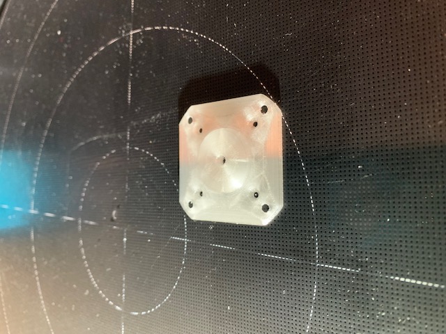
Sorry for the new post. For some reason I can't edit my BOM post. Attached is the STL file for the 5mm axle bearing carrier, edited and tuned to 1 micron. I print this directly in PLA at 50 micron layer height with a 0.4mm nozzle. I slice with the latest Cura with the Arcwelder plugin, 100% concentric infill.
For those designing the CAD file directly, note that every time you move the origin axis for the axles, especially for engagement angle, the contact point of the driver knife edge changes drastically.
For those designing the CAD file directly, note that every time you move the origin axis for the axles, especially for engagement angle, the contact point of the driver knife edge changes drastically.
|
Re: A Very Different Extruder August 10, 2021 12:15AM |
Registered: 5 years ago Posts: 58 |
|
Re: A Very Different Extruder August 10, 2021 08:03AM |
Registered: 4 years ago Posts: 285 |
This is about the 5th time someone's linked to this video. It's a completely different mechanism.
|
Re: A Very Different Extruder December 08, 2021 06:47PM |
Registered: 7 years ago Posts: 15 |
you mention a few posts back that you considered using a bldc, rather than re-wiring it, consider going with a smart controller like the odrive. It needs an encoder, but you don't need to go with a high resolution encoder like people normally do, as you note with 28 positions/rev you can get to 125 steps/mm, so a 7 ppr quad encoder setup (say with a copy photodiods) would be enough resolution, and the bldc will be very happy to spin faster, and to stop/reverse for pulling the filiment back.
a couple other youtube videos of folks doing similar things (but going with much smaller diameter, custom rollers) [www.youtube.com] [www.youtube.com]
a couple other youtube videos of folks doing similar things (but going with much smaller diameter, custom rollers) [www.youtube.com] [www.youtube.com]
|
Re: A Very Different Extruder January 23, 2022 01:04PM |
Registered: 4 years ago Posts: 285 |
Quote
dlang
you mention a few posts back that you considered using a bldc, rather than re-wiring it, consider going with a smart controller like the odrive. It needs an encoder, but you don't need to go with a high resolution encoder like people normally do, as you note with 28 positions/rev you can get to 125 steps/mm, so a 7 ppr quad encoder setup (say with a copy photodiods) would be enough resolution, and the bldc will be very happy to spin faster, and to stop/reverse for pulling the filiment back.
a couple other youtube videos of folks doing similar things (but going with much smaller diameter, custom rollers) [www.youtube.com] [www.youtube.com]
It's interesting that all of these have rollers that appear to be 20 or 30mm tall. If you play with 3 pencils, it becomes quickly apparent that there can be only ONE central point of contact between 3 canted rollers, which is what makes the roller positions and spacing so critical.
Any roller taller than that one point of contact is just wasted space and mass.
|
Re: A Very Different Extruder January 23, 2022 06:07PM |
Registered: 7 years ago Posts: 15 |
Quote
It's interesting that all of these have rollers that appear to be 20 or 30mm tall. If you play with 3 pencils, it becomes quickly apparent that there can be only ONE central point of contact between 3 canted rollers, which is what makes the roller positions and spacing so critical.
Any roller taller than that one point of contact is just wasted space and mass.
The added length would give them room for the bearings and to get the bearings far enough away from the filament to hold them.
I could see tall skinny bearings being lighter than short fat ones (and lave less angular inertia)
you do get a little more than a single point of contact as the sharp edges of the rollers do bite in to the filament, but I agree it's not much more.
|
Re: A Very Different Extruder January 23, 2022 08:26PM |
Registered: 4 years ago Posts: 285 |
Quote
dlang
Quote
It's interesting that all of these have rollers that appear to be 20 or 30mm tall. If you play with 3 pencils, it becomes quickly apparent that there can be only ONE central point of contact between 3 canted rollers, which is what makes the roller positions and spacing so critical.
Any roller taller than that one point of contact is just wasted space and mass.
The added length would give them room for the bearings and to get the bearings far enough away from the filament to hold them.
I could see tall skinny bearings being lighter than short fat ones (and lave less angular inertia)
you do get a little more than a single point of contact as the sharp edges of the rollers do bite in to the filament, but I agree it's not much more.
In case you missed it, here's a video of my design in action, and it pre-dates the other efforts. The rollers are one bearing thick. No more, and no less.
[www.youtube.com]
|
Re: A Very Different Extruder January 23, 2022 09:41PM |
Registered: 7 years ago Posts: 15 |
one bearing thick, but a largish bearing 10mm dia, x 4 mm tall is ~315mm^3
something 4mm dia and 25mm tall would be about the same volume (so similar mass, although bearings are not solid), but smaller diameter, so less angular momentum (i.e. easier to stop and reverse)
I am NOT saying that their design is better, just that it may not be as obviously worse as first glance would have it. I was just pointing out other similar ones, with the idea of cross pollinating ideas.
Your design looks easier to make the working end of.
I'm not thrilled about trying to drill through the center shaft of a stepper. I would just prefer to be able to use a BLDC with the solid pin replaced by a tube rather than trying to drill through the center shaft of a stepper (on many BLDC motors they are designed to be able to be pressed out and replaced)
|
Re: A Very Different Extruder January 24, 2022 09:21AM |
Registered: 4 years ago Posts: 285 |
Quote
dlang
one bearing thick, but a largish bearing 10mm dia, x 4 mm tall is ~315mm^3
something 4mm dia and 25mm tall would be about the same volume (so similar mass, although bearings are not solid), but smaller diameter, so less angular momentum (i.e. easier to stop and reverse)
I am NOT saying that their design is better, just that it may not be as obviously worse as first glance would have it. I was just pointing out other similar ones, with the idea of cross pollinating ideas.
Your design looks easier to make the working end of.
I'm not thrilled about trying to drill through the center shaft of a stepper. I would just prefer to be able to use a BLDC with the solid pin replaced by a tube rather than trying to drill through the center shaft of a stepper (on many BLDC motors they are designed to be able to be pressed out and replaced)
Yes, but. Those excessively long rollers STILL need two bearings each.
And drilling a stepper shaft is trivial on a drill press or lathe. You don't even have to take the motor apart.
|
Re: A Very Different Extruder February 09, 2022 05:27PM |
Registered: 3 years ago Posts: 92 |
Finally got around to finishing my poor man's schnekenstruder, and it actually works! At least mostly. For some reason it doesn't seem to be able to retract. Even with jerk/acceleration set very low, motor current set much too high for continuous running, and retraction distance 0.5mm, it still just makes a suffering noise and fails to rotate backward. But if I command it to rotate forward and backward from the move axis menu, it does it just fine. Takes no effort to do it by hand either, so it must be some sort of software issue.
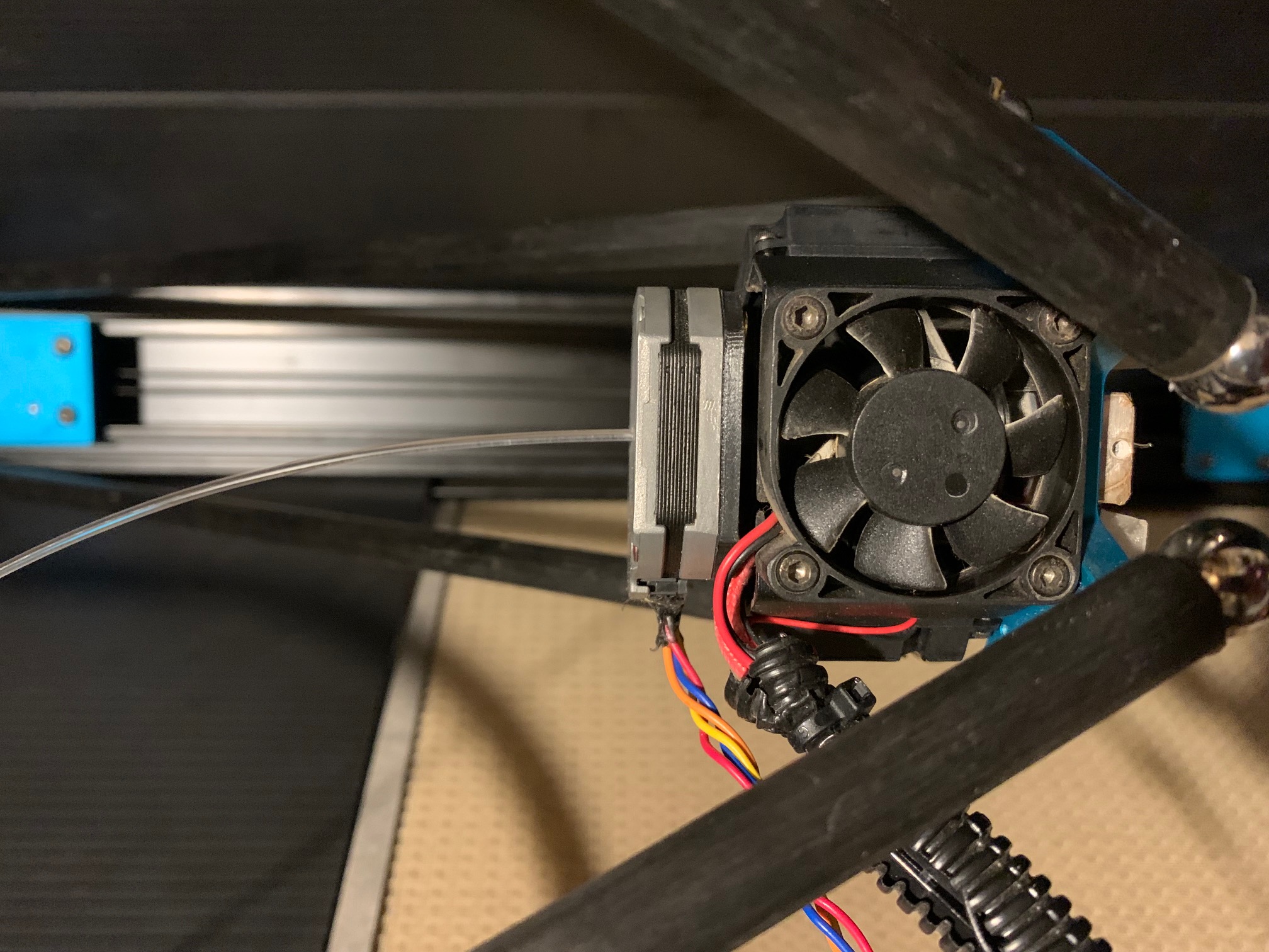
The motor is NEMA14 pancake. I epoxied a 3D printed pneumatic fitting adapter to it for reverse bowden setup. The tube should also serve the purpose of the anti-torque wheel, although from the other thread it sounds like it isn't necessary anyway. I'm still using the bowden heatsink, so there is about a 15mm space between the rollers and where the filament goes into the 2mm heatsink hole. But I don't think it's enough to matter for PLA, which is all I plan to use on this machine.
I reworked the carrier for 4mm bearings. The cutter is 4x8x3mm flanged, sharpened on both sides (to sharpen the difficult side of the flange, I used the same angled block as in my previous post, but with a diamond grit dremel wheel protruding off the top edge). The passive rollers are 4x9x4mm. I just used regular m4x10mm screws and split lock washers instead of the fancy shoulder screws and bellevilles. I did have to file a bevel around the edge of one of the lock washers since it was near impossible to keep it from jamming the smaller diameter cutter bearing. The other two didn't need any custom work, although it can take a couple tries to get them screwed down in the right spot to not jam the bearings.
I currently have it mounted to the printer with screws, but I may change to magnets. Haven't tried unloading it yet...
Thank you rq3 for sharing this brilliant extruder design!
EDIT: Got the retraction issue sorted. Apparently any speed above 5mm/s results in missed steps. Acceleration does not seem to affect it, so I've gone back to the default 10000 and jerk set to 10. Not sure why speed would be such an issue though. Steps per mm is 288 with 0.9 degree full steps, so 5mm/s is only 1440 steps per second. And that's 216RPM, so I wouldn't think torque dropoff would be the problem, especially since motor current doesn't seem to affect it either. I'm currently running a conservative 150mA. The motor is rated for 500mA, but even 250 gets uncomfortably hot after running for half an hour. 200 may be ok, will need to do another half hour test.
I definitely need to upgrade to ABEC 5 bearings. These cheap ones are pretty floppy, giving it some backlash. I can hear it every time it reverses direction, and after printing a retraction test the filament looks pretty chewed up due to not following the spiral groove back. I think the screws and lock washers are fine though. As far as I can tell, the inner race of each bearing is firmly held in place.
Edited 1 time(s). Last edit at 02/10/2022 02:24AM by dekutree64.
|
Re: A Very Different Extruder February 10, 2022 10:14AM |
Registered: 4 years ago Posts: 285 |
Quote
dekutree64
Finally got around to finishing my poor man's schnekenstruder, and it actually works! At least mostly. For some reason it doesn't seem to be able to retract. Even with jerk/acceleration set very low, motor current set much too high for continuous running, and retraction distance 0.5mm, it still just makes a suffering noise and fails to rotate backward. But if I command it to rotate forward and backward from the move axis menu, it does it just fine. Takes no effort to do it by hand either, so it must be some sort of software issue.
The motor is NEMA14 pancake. I epoxied a 3D printed pneumatic fitting adapter to it for reverse bowden setup. The tube should also serve the purpose of the anti-torque wheel, although from the other thread it sounds like it isn't necessary anyway. I'm still using the bowden heatsink, so there is about a 15mm space between the rollers and where the filament goes into the 2mm heatsink hole. But I don't think it's enough to matter for PLA, which is all I plan to use on this machine.
I reworked the carrier for 4mm bearings. The cutter is 4x8x3mm flanged, sharpened on both sides (to sharpen the difficult side of the flange, I used the same angled block as in my previous post, but with a diamond grit dremel wheel protruding off the top edge). The passive rollers are 4x9x4mm. I just used regular m4x10mm screws and split lock washers instead of the fancy shoulder screws and bellevilles. I did have to file a bevel around the edge of one of the lock washers since it was near impossible to keep it from jamming the smaller diameter cutter bearing. The other two didn't need any custom work, although it can take a couple tries to get them screwed down in the right spot to not jam the bearings.
I currently have it mounted to the printer with screws, but I may change to magnets. Haven't tried unloading it yet...
Thank you rq3 for sharing this brilliant extruder design!
EDIT: Got the retraction issue sorted. Apparently any speed above 5mm/s results in missed steps. Acceleration does not seem to affect it, so I've gone back to the default 10000 and jerk set to 10. Not sure why speed would be such an issue though. Steps per mm is 288 with 0.9 degree full steps, so 5mm/s is only 1440 steps per second. And that's 216RPM, so I wouldn't think torque dropoff would be the problem, especially since motor current doesn't seem to affect it either. I'm currently running a conservative 150mA. The motor is rated for 500mA, but even 250 gets uncomfortably hot after running for half an hour. 200 may be ok, will need to do another half hour test.
I definitely need to upgrade to ABEC 5 bearings. These cheap ones are pretty floppy, giving it some backlash. I can hear it every time it reverses direction, and after printing a retraction test the filament looks pretty chewed up due to not following the spiral groove back. I think the screws and lock washers are fine though. As far as I can tell, the inner race of each bearing is firmly held in place.
This is too cool! I did find that ABEC 5 bearings were almost a necessity, that the ground flange had to have a symetrical angle to equalize extrusion and retraction, and that the default retract acceleration in Marlin was WAY too high.
I also found that the filament melting in the nozzle was more than enough "anti-torque", at least with PLA and PETG, so no anti-torque roller is necessary. That was a big surprise, and I'm looking forward to trying some flexible filament, which I have never used before, with any extruder.
Loading filament is obviously no problem. To unload, I uncouple the motor while the nozzle is hot, then just pull the filament out. I then cut the filament just above the motor, and turn the motor until the filament is free. I've tried several "quick coupling" methods for the motor, including magnets and clips, but am currently just using two screws. I don't change the filament often enough to need anything fancier, and I found that the other methods allowed enough microscopic play between the motor and the adapter that the result could show up as almost invisible printing artifacts.
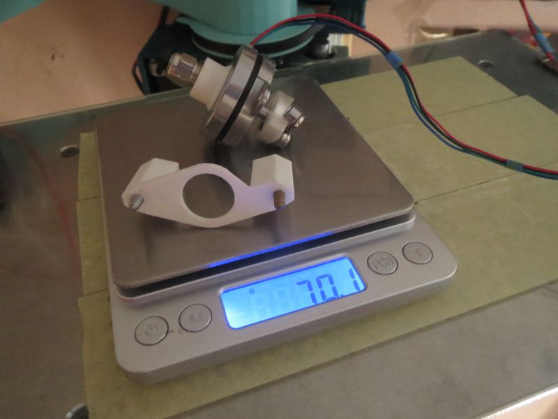
Since I'm running the current NEMA 17 pancake motor at only 0.2 amps (out of 1.0 amp allowed), and the motor stays stone cold even after multi-hour print, I have a NEMA 11 pancake on order that weighs only 28 grams. If it works (and I think it will), that will shave another 42 grams off the assembly, much more than enough to off-set the pure silver heat block.
I already have an adapter plate printed to allow the smaller motor to be directly used on the existing set-up, and just last night I ordered CNC machined 7075 aluminum bearing carriers. Although the printed carrier seems to be holding up nicely, so far.
After printing with this for awhile now, it's apparent that my heatsink is way over-kill, especilly with my DIY tri-metal heat break. I machined the heat sink to fit the existing effector and it's fans, and it uses a groove mount style mate with the drive adapter, which is a lot of excess weight. Redesigning the heatsink let me shave almost half the weight off. If all goes well, this entire thing, from the nozzle to the entry point of the filament into the motor, should mass somewhere around 60 grams.
Edited 3 time(s). Last edit at 02/10/2022 10:28AM by rq3.
|
Re: A Very Different Extruder February 11, 2022 12:03AM |
Registered: 3 years ago Posts: 92 |
Ah, I'm glad I didn't bother with magnets yet then. I recommend using coarse thread screws if you're screwing into plastic. Fewer turns to take them in and out, and at least in my experience machine threads in plastic tend to wear out more quickly.
I have unloaded mine once, and with some gentle turning back and forth by hand I was able to get the lumpy end of the filament through the rollers without having to unscrew the mount. Probably would be better to do it while the filament is still warm so it puts less pressure on the rollers, but it will take some experimentation to find the right time window when it's soft but not sticky. Another option would be to retract part way and then reach in with some nippers and cut the filament between the rollers and heatsink. Then purge the remnant through the nozzle when loading the next filament.
My two-post mount is very nice in terms of usability, since it gives such a clear view and finger access. The long screws support the upward pressure from extrusion just fine, but a three-post mount or full cylinder like yours may be better for high lateral acceleration, to better resist whiplash in all directions. You only really need finger access from one side since it's so easy to turn, but loading and unloading is twice as fast when you can use both hands to spin it.
I look forward to the results with your NEMA 11. My guess is that it will be a bit underpowered. The NEMA 14 seems just right, with enough headroom that you can run cool without worrying about missing steps. Though with an aluminum carrier, a heat-tolerant mounting surface, and no bowden adapter epoxied to it like mine, the stepper should be fine running a little hot.
I still want to try the outrunner design I posted before as well, especially now that we know the anti-torque device is unnecessary. But I won't have a place to put the bowden adapter, so I may have to do it on my other printer. The design is a little mechanically iffy since it puts the extrusion force pulling upward on the roller screws, and pulling upward on the rotor so the shaft retainer clip will have to be shimmed just right so there's no wiggle room. But it should be about as lightweight as you can get.
|
Re: A Very Different Extruder February 13, 2022 10:32PM |
Registered: 10 years ago Posts: 6 |
|
Re: A Very Different Extruder February 14, 2022 12:29PM |
Registered: 4 years ago Posts: 285 |
Quote
dekutree64
Ah, I'm glad I didn't bother with magnets yet then. I recommend using coarse thread screws if you're screwing into plastic. Fewer turns to take them in and out, and at least in my experience machine threads in plastic tend to wear out more quickly.
I look forward to the results with your NEMA 11. My guess is that it will be a bit underpowered. The NEMA 14 seems just right, with enough headroom that you can run cool without worrying about missing steps. Though with an aluminum carrier, a heat-tolerant mounting surface, and no bowden adapter epoxied to it like mine, the stepper should be fine running a little hot.
I still want to try the outrunner design I posted before as well, especially now that we know the anti-torque device is unnecessary. But I won't have a place to put the bowden adapter, so I may have to do it on my other printer. The design is a little mechanically iffy since it puts the extrusion force pulling upward on the roller screws, and pulling upward on the rotor so the shaft retainer clip will have to be shimmed just right so there's no wiggle room. But it should be about as lightweight as you can get.
Agreed, dekutree64! The only screws I have directly threaded into plastic are the two that squeeze the clamp on the adapter to the heatsink. Others, like the motor mount screws, use brass threaded inserts pressed in with a hot drift pin, using a (non-rotating) drill press as an arbor press.
And I, too, suspect that the NEMA 11 may be a bit under-powered (aNEMAic?). The math says it will work, but experience so far says otherwise. We'll see! The current NEMA 17 pancake is only 11.6mm thick and rated for 1.0 amp. I'm running it happily at 0.2 amps, so I have hopes for the NEMA 11 (9.5mm thick), rated for 0.5 amp, but 28 grams versus 70 grams for the current motor.
Thomas Sanladerer of YouTube fame just did a segment on the new E3D hot end, including measurements of just how much force it takes to squeeze molten plastic out of a nozzle. It's not as much as I thought, and the Schnekenstruder has a mechanical advantage of about 21:1.
Edited 1 time(s). Last edit at 02/14/2022 03:43PM by rq3.
|
Re: A Very Different Extruder February 14, 2022 03:34PM |
Registered: 4 years ago Posts: 285 |


Sorry, only registered users may post in this forum.