Outrunner Schnekenstruder
Posted by dekutree64
|
Outrunner Schnekenstruder February 16, 2022 08:14PM |
Registered: 3 years ago Posts: 92 |
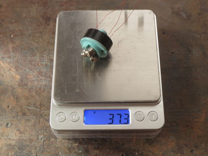
Last July in rq3's Schnekenstruder thread I wrote about my idea to make an outrunner-based version, and finally the dream is realized! It has the same thread as the pneumatic fitting commonly used for bowden tube, so you can screw it into most heatsinks that are designed for bowden use. 37 grams, and probably could be 10 less using a 2204 motor (which is what I ordered, but received a 2208 so I went ahead and used it). It's a $4 gimbal motor from ebay, which is not much good to start with, but the stator core and magnet ring are all I wanted from it and they are fine quality.
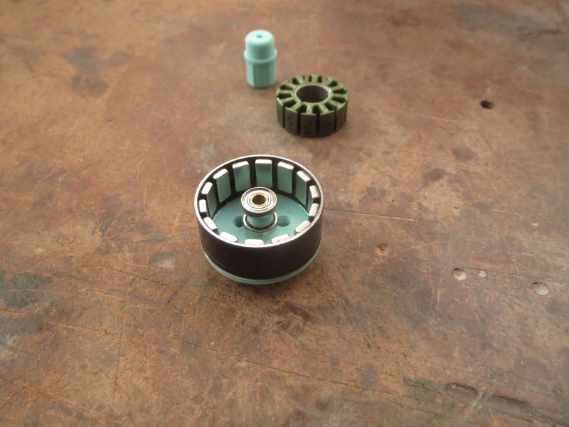
Step 1 is to take it apart. Simply twisting and pulling by hand got the stator off the bearing tube (with it mounted to something for a better grip), and coils had no glue. Other motors I've had to mill the bearing tube out of the stator it was so tight.
Then I milled off the cap of the rotor (and didn't do any cleaner of a job than I would have with a hacksaw). Sand it flat and square. Tip: calipers are not just good for measuring distance; the jaws are parallel, so you can use them to see if one side of the rotor is higher than the other.
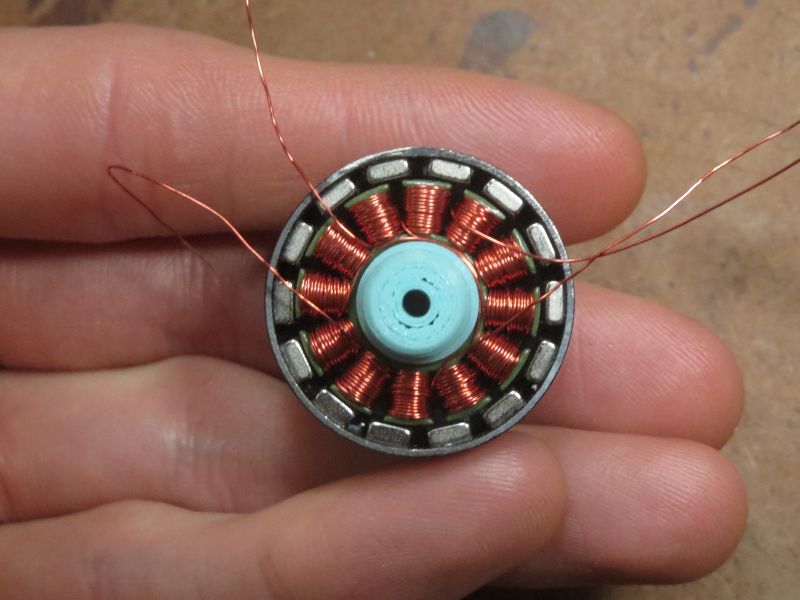
The stator must be rewound as a stepper motor so it can be driven by the usual hardware. I used the winding scheme written about here [hackaday.io] with 30 gauge wire, 45 turns per stator arm (I should have done less, because it took forever and I don't really need to max out the torque). It would probably be possible to design a step/dir board using DRV8313 or something to drive the regular 3-phase windings through their 6 step commutation sequence with current limiting, though it wouldn't be able to do microstepping unless you also put a microcontroller on it to PWM the DRV8313 inputs. And anyway my printer has integrated TMC2209 drivers.
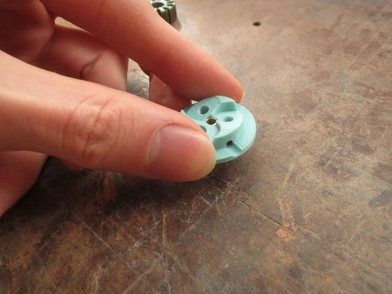
The extruder roller carrier is 3D printed and then drilled and tapped using the jig. The stator mount is printed, and has crush ribs and one larger rib which fits into the keyway in the stator. It will still probably take several attempts to get the fit just right. It needs to be tight in the stator so the rotor magnets don't pull it off when putting the rotor on, but not so tight that it deforms the bearings inside. One nice thing about crush ribs is that you can err on the large side and then file them down until the fit is just right. Unlike filing a full circle, you can clearly see how much material you've removed and keep it even all the way around.
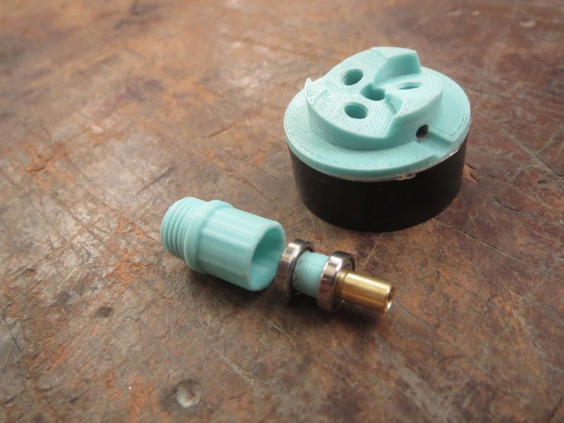
The shaft is 4mm brass tubing, about 14.5mm long. The length doesn't have to be exact, and the ends don't have to be square. The bearings are 4x8x2mm. Rough up an area between 2mm and 6mm from the end. See Parts.jpg for how things should look at this point. Next we will glue everything together with epoxy, so wash the metal parts with soap and water to remove any oil, else the epoxy won't stick.
Put on a rubber glove and epoxy the bearing spacer to the shaft, the rotor spacer to the rotor cap, and the roller carrier to the magnet ring. This can all be done with a single batch of 5 minute epoxy. First apply epoxy to the bearing spacer and shaft, and slide the spacer on. Wipe the excess epoxy off the shaft. Then put on the bearings and rotor spacer, and apply epoxy to the rotor spacer to glue it to the underside of the carrier (not strictly necessary, but saves having to keep track of the little thing). Put the carrier onto the shaft and press downward (ShaftAssembled.jpg). Then apply epoxy to the rim of the magnet ring and stick the rotor onto it (RotorAssembled.jpg). It wouldn't be a bad idea to make a jig to get it perfectly centered. I just did it by eye and came out a tiny bit off (AirGap.jpg), but fortunately not enough for the magnets to make contact. Balance shouldn't be an issue either at the slow rotation rate of extrusion.
After the epoxy sets up, pull the shaft out of the rotor and press it into the stator mount (ShaftIntoStatorMount.jpg). My original idea was that you could use a hot tool to fold the edge of the stator mount over the bearing to retain it, but in practice it was fairly difficult and resulted in a messy appearance so I redid it using epoxy to create the retaining lip.
Now to solder some wires onto it and see if it works...
EDIT: Well that was an epic fail. Magnets rubbing, axial play, and twitching instead of spinning. It seems the shaft hole is a bit loose. I'll re-print the carrier in tougher material, and get it centered better on the magnet ring this time. Hopefully the twitching was just due to magnet rubbing and not a winding error. The axial play is presumably due to some failure of the epoxy lip, so I may have to return to the melting approach. I'll scrape it out and redo it and see if it happens again.
Future improvements would obviously be to machine the carrier and stator mount out of aluminum, and shaft with bearing spacer as a single piece. The stator mount could use an internal snap ring to retain the shaft/bearing assembly, but it would have to be very precise to avoid any axial play. Personally I prefer epoxy.
Another potential improvement would be to stick a PTFE tube in from the bottom that fits tightly in the hole and loosely in the shaft, so the shaft spins around the tube. That would prevent the filament contacting the moving wall of the tube and being torqued a bit.
Edited 1 time(s). Last edit at 02/17/2022 01:47AM by dekutree64.
Step 1 is to take it apart. Simply twisting and pulling by hand got the stator off the bearing tube (with it mounted to something for a better grip), and coils had no glue. Other motors I've had to mill the bearing tube out of the stator it was so tight.
Then I milled off the cap of the rotor (and didn't do any cleaner of a job than I would have with a hacksaw). Sand it flat and square. Tip: calipers are not just good for measuring distance; the jaws are parallel, so you can use them to see if one side of the rotor is higher than the other.
The stator must be rewound as a stepper motor so it can be driven by the usual hardware. I used the winding scheme written about here [hackaday.io] with 30 gauge wire, 45 turns per stator arm (I should have done less, because it took forever and I don't really need to max out the torque). It would probably be possible to design a step/dir board using DRV8313 or something to drive the regular 3-phase windings through their 6 step commutation sequence with current limiting, though it wouldn't be able to do microstepping unless you also put a microcontroller on it to PWM the DRV8313 inputs. And anyway my printer has integrated TMC2209 drivers.
The extruder roller carrier is 3D printed and then drilled and tapped using the jig. The stator mount is printed, and has crush ribs and one larger rib which fits into the keyway in the stator. It will still probably take several attempts to get the fit just right. It needs to be tight in the stator so the rotor magnets don't pull it off when putting the rotor on, but not so tight that it deforms the bearings inside. One nice thing about crush ribs is that you can err on the large side and then file them down until the fit is just right. Unlike filing a full circle, you can clearly see how much material you've removed and keep it even all the way around.
The shaft is 4mm brass tubing, about 14.5mm long. The length doesn't have to be exact, and the ends don't have to be square. The bearings are 4x8x2mm. Rough up an area between 2mm and 6mm from the end. See Parts.jpg for how things should look at this point. Next we will glue everything together with epoxy, so wash the metal parts with soap and water to remove any oil, else the epoxy won't stick.
Put on a rubber glove and epoxy the bearing spacer to the shaft, the rotor spacer to the rotor cap, and the roller carrier to the magnet ring. This can all be done with a single batch of 5 minute epoxy. First apply epoxy to the bearing spacer and shaft, and slide the spacer on. Wipe the excess epoxy off the shaft. Then put on the bearings and rotor spacer, and apply epoxy to the rotor spacer to glue it to the underside of the carrier (not strictly necessary, but saves having to keep track of the little thing). Put the carrier onto the shaft and press downward (ShaftAssembled.jpg). Then apply epoxy to the rim of the magnet ring and stick the rotor onto it (RotorAssembled.jpg). It wouldn't be a bad idea to make a jig to get it perfectly centered. I just did it by eye and came out a tiny bit off (AirGap.jpg), but fortunately not enough for the magnets to make contact. Balance shouldn't be an issue either at the slow rotation rate of extrusion.
After the epoxy sets up, pull the shaft out of the rotor and press it into the stator mount (ShaftIntoStatorMount.jpg). My original idea was that you could use a hot tool to fold the edge of the stator mount over the bearing to retain it, but in practice it was fairly difficult and resulted in a messy appearance so I redid it using epoxy to create the retaining lip.
Now to solder some wires onto it and see if it works...
EDIT: Well that was an epic fail. Magnets rubbing, axial play, and twitching instead of spinning. It seems the shaft hole is a bit loose. I'll re-print the carrier in tougher material, and get it centered better on the magnet ring this time. Hopefully the twitching was just due to magnet rubbing and not a winding error. The axial play is presumably due to some failure of the epoxy lip, so I may have to return to the melting approach. I'll scrape it out and redo it and see if it happens again.
Future improvements would obviously be to machine the carrier and stator mount out of aluminum, and shaft with bearing spacer as a single piece. The stator mount could use an internal snap ring to retain the shaft/bearing assembly, but it would have to be very precise to avoid any axial play. Personally I prefer epoxy.
Another potential improvement would be to stick a PTFE tube in from the bottom that fits tightly in the hole and loosely in the shaft, so the shaft spins around the tube. That would prevent the filament contacting the moving wall of the tube and being torqued a bit.
Edited 1 time(s). Last edit at 02/17/2022 01:47AM by dekutree64.
Attachments:
open | download - Parts.jpg (80 KB)
open | download - ShaftAssembled.jpg (68.9 KB)
open | download - RotorAssembled.jpg (76.4 KB)
open | download - ShaftIntoStatorMount.jpg (76.7 KB)
open | download - FinishedWeight.jpg (75.2 KB)
open | download - AirGap.jpg (67.4 KB)
open | download - Outrunner.zip (366.7 KB)
|
Re: Outrunner Schnekenstruder February 17, 2022 11:25AM |
Registered: 4 years ago Posts: 285 |
|
Re: Outrunner Schnekenstruder March 28, 2022 03:34AM |
Registered: 7 years ago Posts: 15 |
|
Re: Outrunner Schnekenstruder March 28, 2022 02:06PM |
Registered: 3 years ago Posts: 92 |
That may work if you have a motor with three screw holes (or drill and tap two more holes yourself spaced 120 degrees from the first). Otherwise the extruder roller screw holes overlap the motor mounting screw holes. But you would have to deal with the screw heads being in the way of the rollers. They could be counterbored, but that doesn't leave much material left around the roller screw holes. Fine for aluminum, not sure about plastic.
3D printing the whole rotor would have the same problem with flexibility as gluing on a printed cap, but it would probably work if you use a longer hollow shaft than I did and increase thickness of the rotor cap. And 2204 motor would have less trouble in the first place since it would take more angular tilt for the magnets to contact the stator. The motor would be less powerful due to not having the iron ring behind the magnets, unless you use halbach array. That's mostly a matter of finding magnets the right size. But running the numbers for 2204 motor, you could use 4x3x2mm radial-facing magnets, and 4x2x2mm tangential-facing ones, giving a total circumference of (3+2)*14=70mm. Divide by pi and diameter is 22.28mm, just about perfect. And this site has suitable sizes [www.umagnets.com]
You would have to stick two 4x2x1mm together to make 4x2x2, but that should be fine.
|
Re: Outrunner Schnekenstruder September 11, 2023 08:08AM |
Registered: 3 years ago Posts: 92 |
New idea: Mount the extruder on a single 17x23x4mm bearing, with a large gear integrated so it can be turned by a tiny motor off to the side, and have plenty of resolution even with hall sensors (around 150 steps/mm in this case).
I wasn't able to get it to run closed loop (sensor placement trouble, I think), and I may need a larger motor, but I think the concept is viable. This motor is 1404 size, and gets hotter than I'd like above 0.5 amps. Theoretically that should be around 5kg extrusion force, which may be enough, especially since it will keep pushing until it catches up rather than missing steps. But a 1408 motor would fit just as well and double the extrusion force. Would tip the weight over 30 grams though
The small bearings in the middle are intended for a reverse bowden tube, to allow the gear to rotate passively around it. I'm not entirely sure it would work. Movement of the printhead may also cause rotation of the tube relative to the nozzle, and cause extrusion artifacts. Maybe better just to let the gear lightly rub against the filament as it comes in, similar to the hollow stepper shaft in the original Schnekenstruder. It won't be usable on my SCARA printer in any case, which needs a reverse bowden that rigidly holds its rotation relative to the nozzle.
Edited 1 time(s). Last edit at 09/11/2023 08:09AM by dekutree64.
Sorry, only registered users may post in this forum.