CNC vs 3D Print
Posted by rq3
|
CNC vs 3D Print February 16, 2023 08:06PM |
Registered: 4 years ago Posts: 285 |
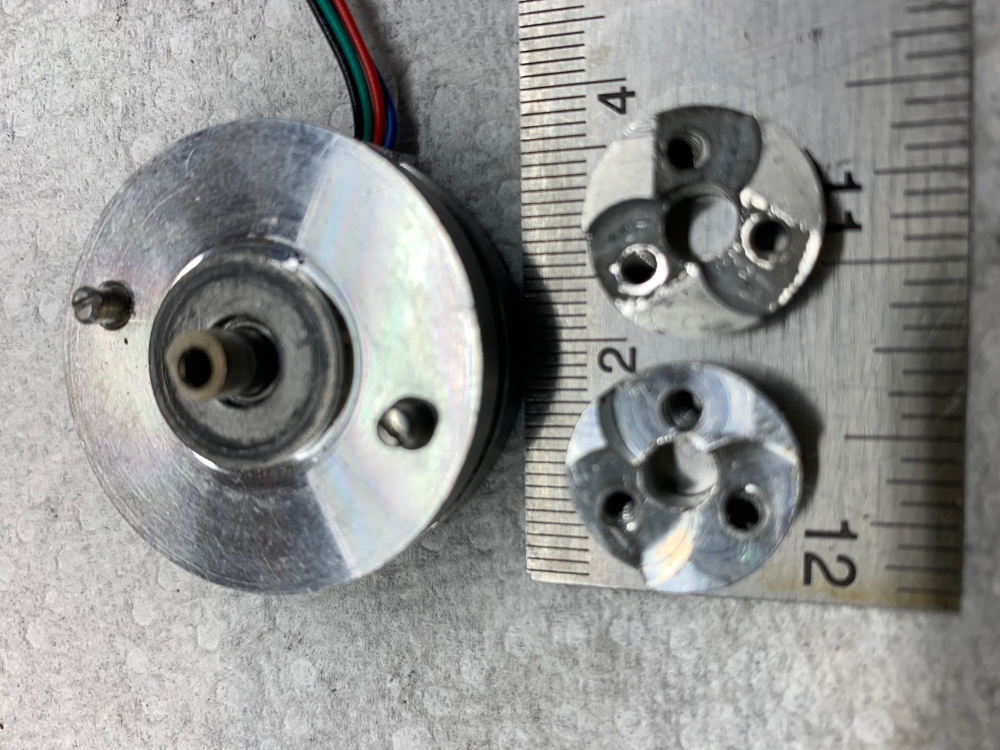
Attached is a photo of bearing carriers for the VDE extruder, against the NEMA14 motor I am currently using.. One (on the left) is CNC machined from 7075-T6 aluminum, at $60 each in lots of five, by hubs.com. The other (on the right) was 3D printed in 316 stainless steel by JLCPCB.com, at $8 each. Shipping was $3, and much faster than expected.
Both parts were fabricated from the same STEP file.
The stainless steel 3D printed part was an absolute bear to post finish. Machining this stuff is like machining bad cast iron with massive inclusions. Carbide tools would work great, except that they are brittle, and the layers and grain boundaries in the part are guaranteed to break the tool, with no way to easily remove it (carbide is not alum soluable). This part spent 3 days in hot alum solution to remove a broken HS steel drill bit. The Z axis dimension is very accurate (within +/- 0.05mm), but the x and y are unuseable.
It was an interesting experiment that I won't soon try again.
Edited 4 time(s). Last edit at 02/16/2023 08:17PM by rq3.
|
Re: CNC vs 3D Print February 16, 2023 08:15PM |
Admin Registered: 16 years ago Posts: 13,884 |
... want you compare 3D-printing vs. lost cast molding from 3D-printed wax parts?
Made something for one of my sisters this way - the "master" was resin-printed, then copied into wax, then LC-molded ... was around 3-5 Euros per part for 100 pieces:
Viktor
--------
Aufruf zum Projekt "Müll-freie Meere" - [reprap.org] -- Deutsche Facebook-Gruppe - [www.facebook.com]
Call for the project "garbage-free seas" - [reprap.org]
Made something for one of my sisters this way - the "master" was resin-printed, then copied into wax, then LC-molded ... was around 3-5 Euros per part for 100 pieces:

Viktor
--------
Aufruf zum Projekt "Müll-freie Meere" - [reprap.org] -- Deutsche Facebook-Gruppe - [www.facebook.com]
Call for the project "garbage-free seas" - [reprap.org]
|
Re: CNC vs 3D Print February 16, 2023 08:22PM |
Registered: 4 years ago Posts: 285 |
Quote
VDX
... want you compare 3D-printing vs. lost cast molding from 3D-printed wax parts?
Made something for one of my sisters this way - the "master" was resin-printed, then copied into wax, then LC-molded ... was around 3-5 Euros per part for 100 pieces:
[attachment 120152 101Freyas.jpg]
I've considered lost print molding, but once you're into hundreds of parts, CNC machining gets to be quite reasonable. At least for my simple part. Not your detail oriented part.
|
Re: CNC vs 3D Print February 17, 2023 02:29AM |
Admin Registered: 16 years ago Posts: 13,884 |
... your part seems to be smaller than my pendants - so even cheaper than 3€ per piece (my was cast from bronze) ... hard to beat this with CNC-milling though 
Viktor
--------
Aufruf zum Projekt "Müll-freie Meere" - [reprap.org] -- Deutsche Facebook-Gruppe - [www.facebook.com]
Call for the project "garbage-free seas" - [reprap.org]
Viktor
--------
Aufruf zum Projekt "Müll-freie Meere" - [reprap.org] -- Deutsche Facebook-Gruppe - [www.facebook.com]
Call for the project "garbage-free seas" - [reprap.org]
|
Re: CNC vs 3D Print February 17, 2023 07:12AM |
Registered: 12 years ago Posts: 1,450 |
A medium-scale way of doing the bearing carrier is to make up a jig that could be fitted in a lathe chuck so that each of the bearing mounting surfaces and internal threads could be cut before turning the block 120º to turn the next position. Old-fashioned (pre-CNC) machinists would make 100 of these before breakfast.
Nice to see that your project is ongoing.
Mike
Nice to see that your project is ongoing.
Mike
|
Re: CNC vs 3D Print February 17, 2023 09:54PM |
Registered: 3 years ago Posts: 92 |
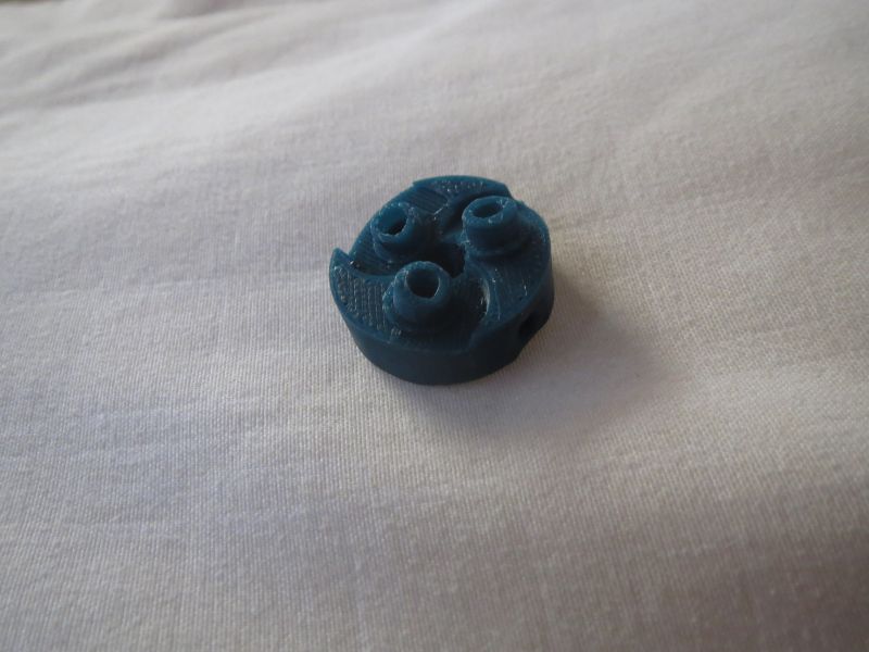
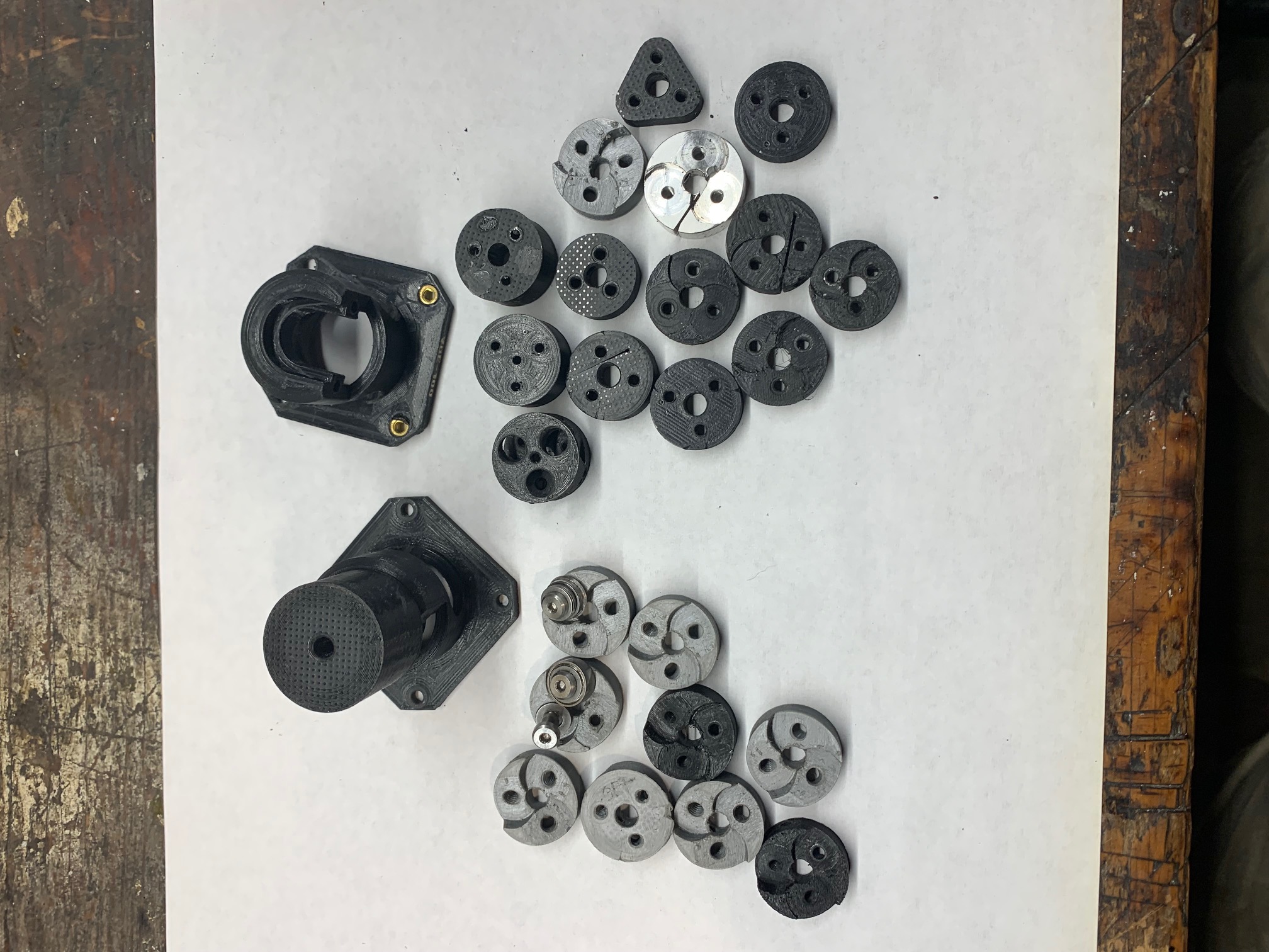
I see no reason to use metal at all anymore. Tom Brazier's style of carrier with integrated hollow posts is a thing of beauty. With a bit of trial and error you can get it to print out ready to use, no cleanup needed (attachment Carrier.jpg). With a belt printer you could just put a bucket at the end and print more than you could ever sell 
Use PLA+ and coarse threaded screws. Grind the tip of one flat to use as a set screw. Regular PLA tends to crack under the continuous stress from a set screw, but PLA+ doesn't, and is a bit more heat resistant. Coarse threads grip really nicely and don't wear out like machine threads in plastic. A cup point set screw would grip the shaft better, but I don't think anyone makes them with coarse threads, and with a flat on the shaft this grips well enough.
So the only difficult production steps are drilling the motor shaft and grinding the cutter bearing flange. I bought a NEMA11 but haven't made a drilling jig for it yet. Hopefully it will go easily this time by drilling it from both ends.
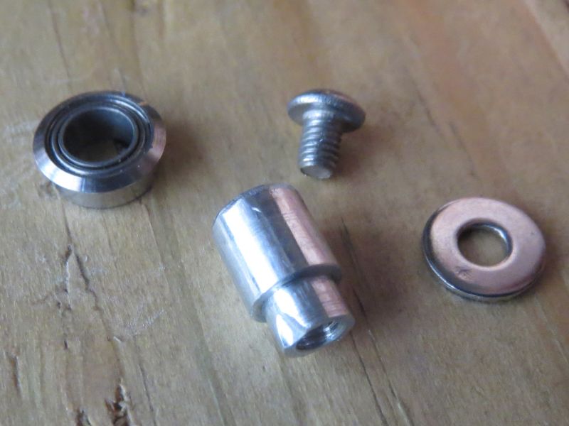
I also bought an ABEC-7 bearing to use as the cutter. Since I don't have a 3/16" collet, I made a little adapter that steps down from 1/4" to 3/16" (BearingHolder.jpg, note: the scoop taken out of the corner was a mistake but doesn't hurt functionality). I also drilled and tapped a hole in the center, so I can use a screw to keep the bearing from pulling off when grinding the underside of the flange, as it often did when it was only held on by hot glue. But I do still use hot glue around the outside of the bearing to prevent it from spinning.
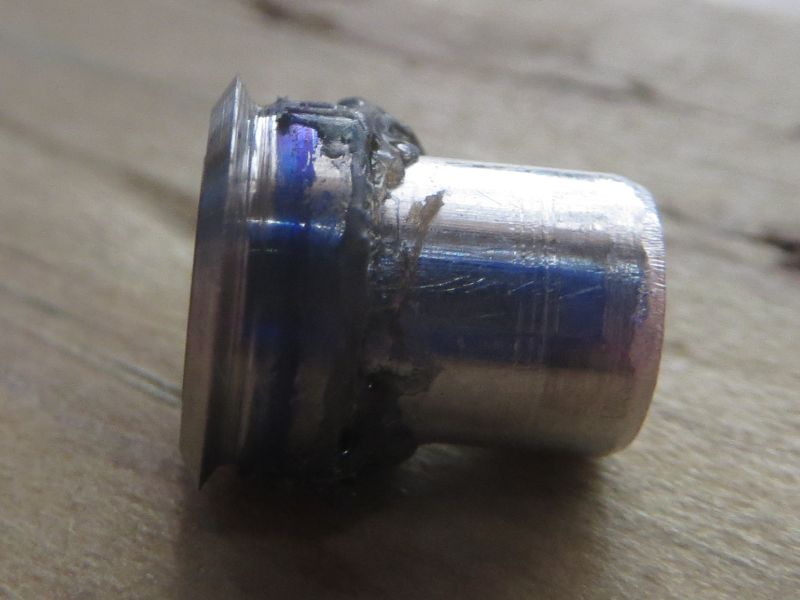
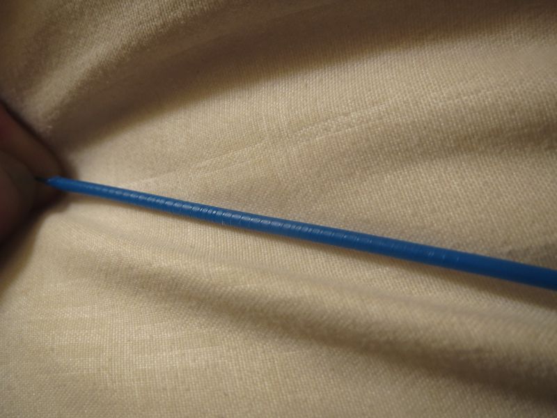
I grind the flange using an angled piece of 2x4 with diamond dremel wheel protruding off the edge, with an aluminum disc for support (GrindingUnderside.jpg). The aluminum disc does not contact the spindle, and screw head does not contact the wood, although they are both close to it. The only contact is between the diamond wheel and bearing flange. The outer bevel is ground using diamond stones on the angled 2x4 with bearing held on only by hot glue (Grinding.jpg), no different from my previous experiments. Final result is CutterCloseup.jpg. Looks pretty near perfect to me, but it still doesn't follow the same helix after retracting (Helix.jpg). Not sure what more I can do.
The .stl may not perfectly match the Blender file. It is what prints perfectly on my printer. If it's not right on yours, open the .blend and scale the hole diameters and bearings posts as necessary, apply all the booleans, and export stl.
Edited 3 time(s). Last edit at 02/18/2023 02:31AM by dekutree64.
Use PLA+ and coarse threaded screws. Grind the tip of one flat to use as a set screw. Regular PLA tends to crack under the continuous stress from a set screw, but PLA+ doesn't, and is a bit more heat resistant. Coarse threads grip really nicely and don't wear out like machine threads in plastic. A cup point set screw would grip the shaft better, but I don't think anyone makes them with coarse threads, and with a flat on the shaft this grips well enough.
So the only difficult production steps are drilling the motor shaft and grinding the cutter bearing flange. I bought a NEMA11 but haven't made a drilling jig for it yet. Hopefully it will go easily this time by drilling it from both ends.
I also bought an ABEC-7 bearing to use as the cutter. Since I don't have a 3/16" collet, I made a little adapter that steps down from 1/4" to 3/16" (BearingHolder.jpg, note: the scoop taken out of the corner was a mistake but doesn't hurt functionality). I also drilled and tapped a hole in the center, so I can use a screw to keep the bearing from pulling off when grinding the underside of the flange, as it often did when it was only held on by hot glue. But I do still use hot glue around the outside of the bearing to prevent it from spinning.
I grind the flange using an angled piece of 2x4 with diamond dremel wheel protruding off the edge, with an aluminum disc for support (GrindingUnderside.jpg). The aluminum disc does not contact the spindle, and screw head does not contact the wood, although they are both close to it. The only contact is between the diamond wheel and bearing flange. The outer bevel is ground using diamond stones on the angled 2x4 with bearing held on only by hot glue (Grinding.jpg), no different from my previous experiments. Final result is CutterCloseup.jpg. Looks pretty near perfect to me, but it still doesn't follow the same helix after retracting (Helix.jpg). Not sure what more I can do.
The .stl may not perfectly match the Blender file. It is what prints perfectly on my printer. If it's not right on yours, open the .blend and scale the hole diameters and bearings posts as necessary, apply all the booleans, and export stl.
Edited 3 time(s). Last edit at 02/18/2023 02:31AM by dekutree64.
Attachments:
open | download - Carrier.jpg (67.2 KB)
open | download - BearingHolder.jpg (63.3 KB)
open | download - GrindingUnderside.jpg (49.8 KB)
open | download - CutterCloseup.jpg (55.2 KB)
open | download - Helix.jpg (74 KB)
open | download - CarrierBoca.blend (1.22 MB)
open | download - CarrierBoca.stl (239.6 KB)
open | download - Grinding.jpg (54.3 KB)
|
Re: CNC vs 3D Print February 18, 2023 04:53PM |
Registered: 4 years ago Posts: 285 |
Quote
dekutree64
I see no reason to use metal at all anymore. Tom Brazier's style of carrier with integrated hollow posts is a thing of beauty. With a bit of trial and error you can get it to print out ready to use, no cleanup needed (attachment Carrier.jpg). With a belt printer you could just put a bucket at the end and print more than you could ever sell
So the only difficult production steps are drilling the motor shaft and grinding the cutter bearing flange. I bought a NEMA11 but haven't made a drilling jig for it yet. Hopefully it will go easily this time by drilling it from both ends.
.
I probably printed 100 prototypes in PLA, and they worked fine as long as the motor didn't get too warm.
If you have a decent drill press, drilling the shaft is trivial. Chuck the motor shaft in the drill press, lower the motor to the table with the quill, and firmly clamp the motor body in place. Loosen the chuck, raise the quill, and insert a 135 degree, split point, 2mm diameter high speed steel bit in the chuck. It will, of course, be as perfectly aligned with the motor shaft as your chuck will allow, due to the exercize above. A split point drill won't wander the way a "standard" hardware store drill does, but you can always start with a center drill before switching over to the 2mm. A small vice-grip plier on the motor shaft prevents it from spinning while drilling.
I have yet to find a motor shaft that can't be drilled this way in one shot. Even the rare case hardened shaft.
Edited 1 time(s). Last edit at 02/18/2023 04:57PM by rq3.
|
Re: CNC vs 3D Print February 18, 2023 08:19PM |
Registered: 4 years ago Posts: 90 |
An idea about drilling the shaft...
With a drill press (fixed part, spinning drill bit), the drill tends to deviate. Moreover, drill press chucks usually have a huge runout. With a lathe it's the opposite : the drill tends to auto center, even without center drilling, or with a poorly aligned tailstock. It's a fact, experienced it many times, never understood why... Recently confirmed, one more time, by an old retired machinist.
What about spinning the motor while keeping the drill bit fixed ?
1000-2000 RPM is on the low side for a 2mm drill bit, but could do it.
Could even spin the drill press and run the motor in the opposite direction, adding RPMs...
[EDIT] I use split point drills only, and always with collets. My feelings could be biased
Edited 2 time(s). Last edit at 02/18/2023 08:25PM by yet-another-average-joe.
|
Re: CNC vs 3D Print February 18, 2023 08:58PM |
Registered: 4 years ago Posts: 285 |
Quote
yet-another-average-joe
An idea about drilling the shaft...
With a drill press (fixed part, spinning drill bit), the drill tends to deviate. Moreover, drill press chucks usually have a huge runout. With a lathe it's the opposite : the drill tends to auto center, even without center drilling, or with a poorly aligned tailstock. It's a fact, experienced it many times, never understood why... Recently confirmed, one more time, by an old retired machinist.
What about spinning the motor while keeping the drill bit fixed ?
1000-2000 RPM is on the low side for a 2mm drill bit, but could do it.
Could even spin the drill press and run the motor in the opposite direction, adding RPMs...
[EDIT] I use split point drills only, and always with collets. My feelings could be biased
We're on the same page. I heard horror stores about machining titanium, but found it delightful when I actually tried it. I use Grade 5 Titanium for parts that need the lowest possible heat conductivity, like heat breaks. For drilling a 2mm hole 16mm deep, I found that 800 RPM (to reduce heat and hardening), with very heavy feed rates to avoid work hardening works very well. Black oxide bits, no lubricant. This is completely contrary to anything you find on the interwebs, but it works for me.
For turning a 6mm diameter titanium part, 1200 RPM, heavy bites (at least 4 thou per pass), very sharp C2 carbide, no lubricant, zero top rake. 5 degrees on all others. Again, completely against the "common wisdom" grain, but, hey, it works. At least for me.
Edited 2 time(s). Last edit at 02/18/2023 09:00PM by rq3.
|
Re: CNC vs 3D Print February 18, 2023 11:49PM |
Registered: 3 years ago Posts: 92 |
Yeah, regular PLA will certainly work. It just might need replaced periodically, whereas PLA+ with coarse threads will probably be trouble-free for many years.Quote
rq3
I probably printed 100 prototypes in PLA, and they worked fine as long as the motor didn't get too warm.
I shall add that to my list of desired tools!Quote
rq3
135 degree, split point, 2mm diameter high speed steel bit
I finally got it to follow the helix when retracting. I had left the wrong pressure roller bearings on it from some previous test. After switching to ABEC-5 it works perfectly. This confirms that all 3 bearings must be ABEC-5 or better, not just the cutter.
So now I can produce these things for around $25 in bearings, $25 motor, and probably an hour of work. But should I? I would be profiting from your original design and Tom Brazier's improved carrier. I could share some of the profit. Mostly I just want them to be available to people without expensive machinery, and if you're not interested in producing them then somebody has to do it
Apparently my promoting the DIY version hasn't gotten much notice. CNC Kitchen just posted an extruder comparison video, but no mention of it.
|
Re: CNC vs 3D Print February 20, 2023 02:48PM |
Registered: 3 years ago Posts: 26 |
I'm not surprised that Stefan of CNC Kitchen did not include your brilliant extruder in his testing. He has probably never even heard of it. The only place that I've ever noticed discussion of your extruder is this forum, and this forum has become very, very quiet in the last few years. Perhaps you should contact him directly, and send him an extruder to play with. He'll be interested for sure.
|
Re: CNC vs 3D Print February 26, 2023 02:49AM |
Registered: 3 years ago Posts: 92 |
Ok, my NEMA11 is complete.
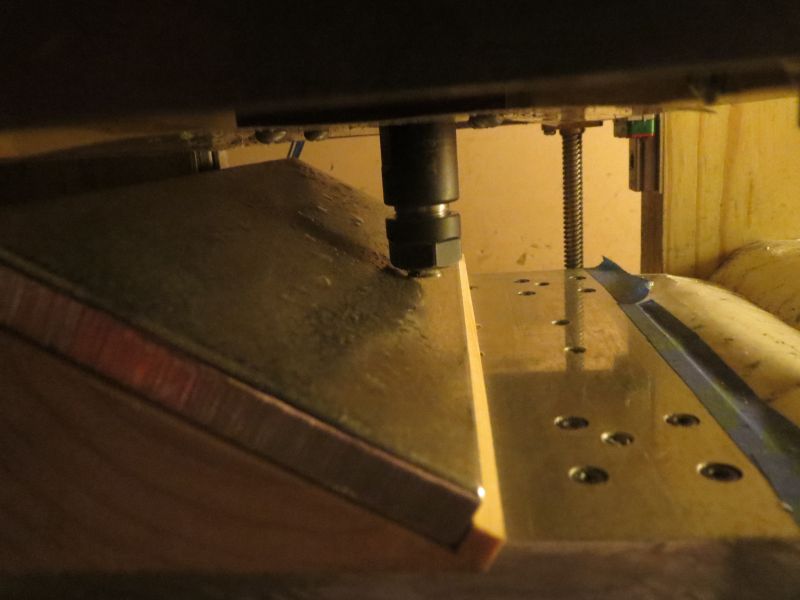
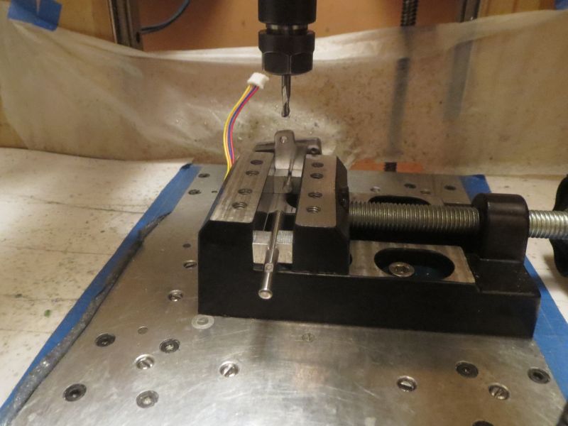
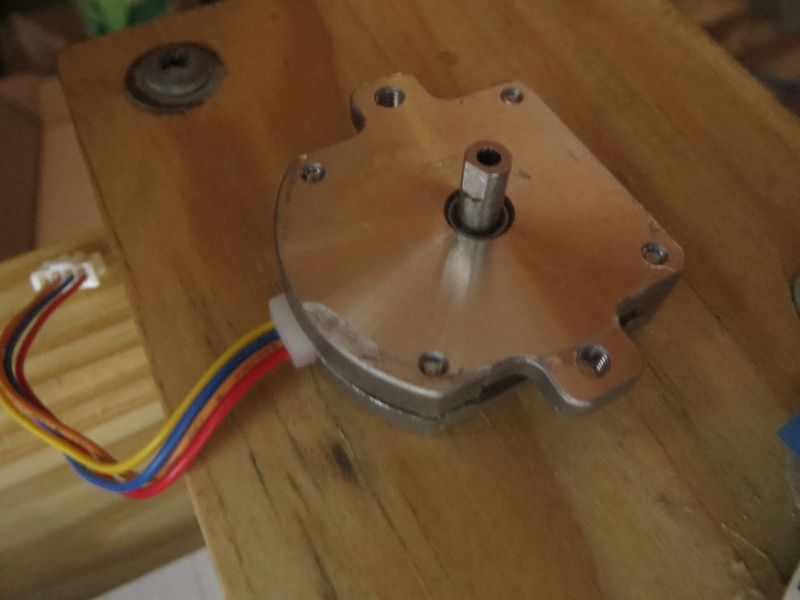
I wanted to add a flat on the shaft, and thought it would be nice to shorten it by 3mm as well, so I decided to do both at once on the mill. I made some little clamping assist blocks, 14x8x6mm with a 4mm hole in the center, and then cut in half. Two of them hold the motor shaft square in the vise, and the other two hold a random piece of 4mm rod to support the other side of the jaws (in hindsight I could have just used anything 14mm wide for that...). Can you spot the mistake waiting to happen in MillingShaft.jpg? The endmill isn't sticking out far enough, and resulted in the chuck running into the motor and roughing it up. Fortunately happened before getting too close to any final dimensions, so no harm done aside from appearance. Re-did the setup and continued on.
Shaft drilling was trouble again. I made another tool I've been wanting for a while (ChuckHolder.jpg), which is a way to mount a spare ER11 chuck to the bed facing up so I can use it either for workholding, or toolholding with the workpiece in the spindle like a lathe. To get it centered, I clamp a 3mm rod in the spindle, and a 1/4" OD, 3mm ID ring in the stationary chuck. With the rod in the hole, they are held in alignment while tightening down the screws.
Unfortunately I did not verify the angular alignment of the chuck holder, which was slightly off and resulted in a broken 1.5mm drill. At least I had the sense to do a practice run drilling a hole through a piece of 4mm rod rather than the actual motor shaft, so it was no problem to have the broken bit stuck in it. I never did think to check angular alignment at the time, and instead just drilled a shallow hole in the motor shaft and gave up on it.
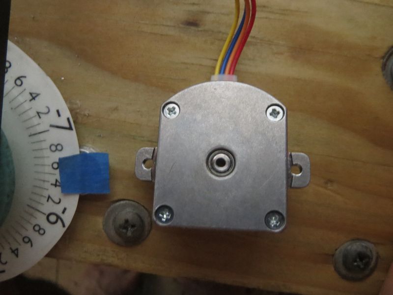
Then I clamped the motor down to the table, got all centered up on the shaft (would have been easier if I had a good 4mm collet...), clamped some vise grips on it (worked great), and proceeded with drilling the usual way. This seemed to go relatively smoothly, yet still came out slightly off center at the other end. Probably due to use of a Chinese 2mm collet.
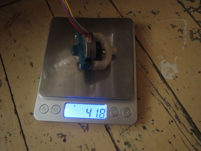
NEMA11Weight.jpg is the finished extruder. 42 grams including a new mount and reverse bowden design. The mount screws into a V6 hotend designed for bowden tube. Possible that it will need some sort of locking mechanism to keep it from wiggling loose, but I'll do some printing with it and see if it's actually an issue. Note that this mount is designed for the shortened motor shaft. With the original 10mm long shaft, the mount arms would need to be 3mm taller.
For the bowden adapter, instead of printing internal threads for a pneumatic fitting, I just printed a barbed 4mm hole that is held on by the same screws that hold the motor itself. Lighter weight, cheaper, and doesn't have to be epoxied to the motor like my previous design so heat is less of a threat. The screw holes intentionally do not go quite all the way through. This allows printing it with concentric supports, where the first floating layer bridges between the support lines, and subsequent layers have the screw holes. A little bit of manual labor to cut them through, but not bad.
The V6 hotend is about 56 grams, so together the weight is just under 100g (excluding any part cooling fan you may add).
Performance-wise, the initial test did not look good. Largely unable to turn. But after printing a new carrier with 0.05mm less blade penetration into the filament, it works much better and still has more than enough grip. I was getting some missed steps when pushing PLA through a 200C 0.5mm nozzle at 5mm/s, but after reducing speed to 1mm/s I don't think it's missing. But I'm not entirely sure because my steps per mm adjustments were not giving predictable results. I ended up on 230 steps per mm by trial and error. Tomorrow I'll do some actual prints with it and see how they turn out, and how hot the motor gets when running continuously at the rated 300mA.
I wanted to add a flat on the shaft, and thought it would be nice to shorten it by 3mm as well, so I decided to do both at once on the mill. I made some little clamping assist blocks, 14x8x6mm with a 4mm hole in the center, and then cut in half. Two of them hold the motor shaft square in the vise, and the other two hold a random piece of 4mm rod to support the other side of the jaws (in hindsight I could have just used anything 14mm wide for that...). Can you spot the mistake waiting to happen in MillingShaft.jpg? The endmill isn't sticking out far enough, and resulted in the chuck running into the motor and roughing it up. Fortunately happened before getting too close to any final dimensions, so no harm done aside from appearance. Re-did the setup and continued on.
Shaft drilling was trouble again. I made another tool I've been wanting for a while (ChuckHolder.jpg), which is a way to mount a spare ER11 chuck to the bed facing up so I can use it either for workholding, or toolholding with the workpiece in the spindle like a lathe. To get it centered, I clamp a 3mm rod in the spindle, and a 1/4" OD, 3mm ID ring in the stationary chuck. With the rod in the hole, they are held in alignment while tightening down the screws.
Unfortunately I did not verify the angular alignment of the chuck holder, which was slightly off and resulted in a broken 1.5mm drill. At least I had the sense to do a practice run drilling a hole through a piece of 4mm rod rather than the actual motor shaft, so it was no problem to have the broken bit stuck in it. I never did think to check angular alignment at the time, and instead just drilled a shallow hole in the motor shaft and gave up on it.
Then I clamped the motor down to the table, got all centered up on the shaft (would have been easier if I had a good 4mm collet...), clamped some vise grips on it (worked great), and proceeded with drilling the usual way. This seemed to go relatively smoothly, yet still came out slightly off center at the other end. Probably due to use of a Chinese 2mm collet.
NEMA11Weight.jpg is the finished extruder. 42 grams including a new mount and reverse bowden design. The mount screws into a V6 hotend designed for bowden tube. Possible that it will need some sort of locking mechanism to keep it from wiggling loose, but I'll do some printing with it and see if it's actually an issue. Note that this mount is designed for the shortened motor shaft. With the original 10mm long shaft, the mount arms would need to be 3mm taller.
For the bowden adapter, instead of printing internal threads for a pneumatic fitting, I just printed a barbed 4mm hole that is held on by the same screws that hold the motor itself. Lighter weight, cheaper, and doesn't have to be epoxied to the motor like my previous design so heat is less of a threat. The screw holes intentionally do not go quite all the way through. This allows printing it with concentric supports, where the first floating layer bridges between the support lines, and subsequent layers have the screw holes. A little bit of manual labor to cut them through, but not bad.
The V6 hotend is about 56 grams, so together the weight is just under 100g (excluding any part cooling fan you may add).
Performance-wise, the initial test did not look good. Largely unable to turn. But after printing a new carrier with 0.05mm less blade penetration into the filament, it works much better and still has more than enough grip. I was getting some missed steps when pushing PLA through a 200C 0.5mm nozzle at 5mm/s, but after reducing speed to 1mm/s I don't think it's missing. But I'm not entirely sure because my steps per mm adjustments were not giving predictable results. I ended up on 230 steps per mm by trial and error. Tomorrow I'll do some actual prints with it and see how they turn out, and how hot the motor gets when running continuously at the rated 300mA.
Attachments:
open | download - MillingShaft.jpg (67.7 KB)
open | download - MachinedShaft.jpg (52.1 KB)
open | download - OffCenter.jpg (57.1 KB)
open | download - NEMA11Weight.jpg (60.9 KB)
open | download - NEMA11Mount.stl (164.6 KB)
open | download - BowdenAdapter.stl (53.5 KB)
open | download - NEMA11Mount.blend (1.61 MB)
open | download - ChuckHolder.jpg (57.9 KB)
|
Re: CNC vs 3D Print February 26, 2023 08:25PM |
Registered: 3 years ago Posts: 92 |
Initial printing tests are not looking good. Lots of underextrusion, especially at the start of each line. Retract moves were failing entirely (vibrating in place) until I lowered the max velocity to 3mm/s, and still sometimes failed to de-retract. 2mm/s doesn't visibly skip, but apparently is still missing some steps.
It's also back to not following the helix after retracting, probably due to the decreased blade penetration.
The 300mA current rating seems to be quite conservative actually. I went up to 450 and the motor was still not too hot to keep my hand in contact with it. I didn't push it to 500, but that would probably be comparable to the level of heating you get with the rated current of NEMA17 steppers.
Maybe my imperfect shaft hole is giving it some resistance. I could drill it out to 2.5mm like I did on the NEMA14 before.
|
Re: CNC vs 3D Print February 27, 2023 12:43PM |
Registered: 4 years ago Posts: 285 |
Quote
dekutree64
Initial printing tests are not looking good. Lots of underextrusion, especially at the start of each line. Retract moves were failing entirely (vibrating in place) until I lowered the max velocity to 3mm/s, and still sometimes failed to de-retract. 2mm/s doesn't visibly skip, but apparently is still missing some steps.
It's also back to not following the helix after retracting, probably due to the decreased blade penetration.
The 300mA current rating seems to be quite conservative actually. I went up to 450 and the motor was still not too hot to keep my hand in contact with it. I didn't push it to 500, but that would probably be comparable to the level of heating you get with the rated current of NEMA17 steppers.
Maybe my imperfect shaft hole is giving it some resistance. I could drill it out to 2.5mm like I did on the NEMA14 before.
The NEMA-11 in your photos looks very much like the one I tried, without much success. It just didn't have quite enough torque. The round NEMA-14 seems like the sweet spot. Works as well as the NEMA-17, but is much lighter.
I tried driver voltages of up to 45VDC on the NEMA-11 to try to get it to co-operate, but it was a real balancing act between available torque and motor heat. Most folks freak out when their steppers get hot, but they are designed to run that way. The problem was that filament like standard PLA can't tolerate the dwell time inside a hot motor shaft.
A few thoughts should you try to "commercialize" my idea. Ultra-low head profile, precision shoulder screws are obscenely expensive. Unless you talk to the manufacturers themselves. A screw that costs $12 each is about $0.40 if you commit to 1000. Then you can make the carrier correctly, with a proper Belleville spring, and not rely on flexible plastics to maintain critical (as you know) tolerances. My final Imperial carrier STL file is attached. It includes all the "secret sauce" dimensions (like X and Y axis offsets to compensate for the bearing cant) that my previous designs included, but not to this level of detail. It prints and works very well in PETG with Imperial 5/16" bearings, which is what it was designed for. The knife edge is 0.328" diameter, 60 degree included angle. The carrier I am currently using is CNC machined from 7075-T6 aluminum.
Metric bearings have far fewer "options" than Imperial bearings. Sizes, flanges, materials, and tolerances are very much more available in the Imperial world. And cheaper. Which makes a weird kind of sense, since a millimeter is about 0.04 inch. Pretty large and gross in the bearing industry. If you wanted to go nuts, you can get an ABEC5 Imperial flanged bearing with a manufactured ground knife edge, for about $140. All ceramic. In single piece quantities. By all ceramic, I mean races AND balls. In metric, you will be laughed at.
Finally, I have manufactured and sold aviation related items for decades, and recently stopped doing so. As you can imagine, the hoops I had to jump through with the Federal government (FAA) to produce something installed on an aircraft were not trivial. But three things made me quit:
1) I'm retired, and don't need the hassle or income.
2) The chips I need for the electronics are now unobtainium.
3) Humans have become phenomenally stupid.
The last item above was the clincher. Having been in the avionics business since the late 1970's, it has only been within the last 10 or 12 years that I started receiving phone calls and e-mails regarding technical support that were, frankly, beyond belief. The sheer lack of basic knowledge or troubleshooting skills frightened me. And these were from "technicians" certified and licensed by the FAA to actually work on airplanes. I won't go into details, but we're talking "which way do I rotate the wrench to remove the nut" kinds of questions.
So. If you do decide to commercialize this thing, send me $1 per kit on your honor, and expect to spend all of your free time dealing with the clueless, because I'll have nothing to do with them, unless VERY carefully approached. I imagine the first thing you'll run into is "will this work/fit/adapt to my Squeezle 3000/Creality/Anycubic wonder printer", or "I followed the recipe exactly, BUT the chronosynclastic infidibulum won't clear the tremmy bearing". Have fun.
Edited 4 time(s). Last edit at 02/27/2023 08:24PM by rq3.
|
Re: CNC vs 3D Print February 27, 2023 08:34PM |
Registered: 4 years ago Posts: 285 |
Quote
leadinglights
A medium-scale way of doing the bearing carrier is to make up a jig that could be fitted in a lathe chuck so that each of the bearing mounting surfaces and internal threads could be cut before turning the block 120º to turn the next position. Old-fashioned (pre-CNC) machinists would make 100 of these before breakfast.
Nice to see that your project is ongoing.
Mike
That won't work (easily) in a lathe, but will easily work in a mill. The angled bearing screw holes are offset in two axes from the centerline. Been there, done that, see previous posts.
Yes, it's easy once jigged, but not worth the time for me.
Sorry, only registered users may post in this forum.