Home
>
RepRap User Groups
>
Europe
>
Italy RepRap User Group - Gruppo RepRap Italia
>
Discussioni generali - NO PROBLEMI DELLA STAMPANTE
>
Topic
Prime prove e primi test
Posted by INCO
|
Prime prove e primi test April 09, 2013 02:45PM |
Registered: 11 years ago Posts: 108 |
|
Re: Prime prove e primi test April 10, 2013 10:43AM |
Registered: 11 years ago Posts: 1,865 |
|
Re: Prime prove e primi test April 10, 2013 04:21PM |
Registered: 12 years ago Posts: 964 |
> ciao,
> devi prima far "sentire i fine corsa, immagino,
> premento i pulsanti del "torna a casa lessi"
Presumo che INCO da una risposta del genere non abbia capito nulla. Vediamo di fare meno gli spiritosi e dare risposte esaustive e semplici. Tutti qui hanno iniziato facendo queste domande.
Cmq collega gli endsto (seguendo lo schematico della tua scheda elettronica). Da repetier nella scheda “controllo manuale”, clicca sulle caselle a forma di cassetta. I motori a questo punto si muoveranno finché non troveranno l'endstop che li ferma. Fatto ciò potrai muovere in ambo le direzioni i carrelli.
Ivan
|
Re: Prime prove e primi test April 10, 2013 04:56PM |
Registered: 11 years ago Posts: 1,865 |
|
Re: Prime prove e primi test April 10, 2013 05:08PM |
Registered: 12 years ago Posts: 964 |
|
Re: Prime prove e primi test April 11, 2013 06:08AM |
Registered: 11 years ago Posts: 108 |
 Stasera dopo il lavoro, appena ho la macchina di nuovo sotto mano, vedo di impostare il tutto...e magari di fare la prima stampa!!!
|
Re: Prime prove e primi test April 12, 2013 06:58AM |
Registered: 11 years ago Posts: 108 |
Buongiorno a tutti. Ho collegato correttamente i fine corsa. Ho fatto la prova con il chiamiamolo "torna a casa lessie" ed effettivamente i motori si muovono piano piano fino ai fine corsa. Appena toccati tornano indietro di pochi mm, però, anche con questa operazione, i motori non tornano indietro sugli assi x,y,z. quando lo richiedo io... Cosa può essere? Voglio far presente che i pololu scaldano tantissimo nell'arco dei pochi secondi di prova (30/60 sec.) è normale?
Grazie
Inco
Grazie
Inco
|
Re: Prime prove e primi test April 12, 2013 07:06AM |
Registered: 11 years ago Posts: 108 |
|
Re: Prime prove e primi test April 12, 2013 07:45AM |
Registered: 12 years ago Posts: 964 |
Hai problemi di attrito ed il motore perde passi. Da qui il surriscaldamento dei driver...
-------------------------------------------------------
> Voglio puntualizzare che, quando li richiamo
> indietro (in verso negativo) sembra che i motori
> si sforzino (anche rimanendo fermi) e si sente un
> rumore tipo tum-tum-tum...
-------------------------------------------------------
> Voglio puntualizzare che, quando li richiamo
> indietro (in verso negativo) sembra che i motori
> si sforzino (anche rimanendo fermi) e si sente un
> rumore tipo tum-tum-tum...
|
Re: Prime prove e primi test April 12, 2013 08:48AM |
Registered: 11 years ago Posts: 67 |
Anche se sono fermi i motori sono sempre alimentati, lo senti dal fatto che sono "duri" da muovere.
Se i driver Pololu scaldano significa che non sono tarati e scorre una corrente eccessiva.
Regola i trimmer come spiegato nei wiki, altrimenti si danneggiano.
Fallo subito prima di continuare gli esperimenti.
ciao
Eugenio
Se i driver Pololu scaldano significa che non sono tarati e scorre una corrente eccessiva.
Regola i trimmer come spiegato nei wiki, altrimenti si danneggiano.
Fallo subito prima di continuare gli esperimenti.
ciao
Eugenio
|
Re: Prime prove e primi test April 12, 2013 03:14PM |
Registered: 11 years ago Posts: 108 |
Ciao Ivan ,cosa intendi precisamente per problemi di attrito? La macchina dovrebbe essere stata montata in maniera corretta e non dovrebbe esserci nulla fuori squadra, manualmente scorre tutto abbastanza bene...
Per reolare i trimmer basta ruotare in senso antiorario la piccola croce che csi trova sui pololu? Di quanto? In parole povere facendo così arriverebbe meno corrente anche ai motori?
Grazie.
Inco
Per reolare i trimmer basta ruotare in senso antiorario la piccola croce che csi trova sui pololu? Di quanto? In parole povere facendo così arriverebbe meno corrente anche ai motori?
Grazie.
Inco
|
Re: Prime prove e primi test April 13, 2013 01:42AM |
Registered: 11 years ago Posts: 67 |
|
Re: Prime prove e primi test April 13, 2013 09:23AM |
Registered: 11 years ago Posts: 108 |
|
Re: Prime prove e primi test April 13, 2013 10:25AM |
Registered: 11 years ago Posts: 67 |
|
Re: Prime prove e primi test April 13, 2013 10:54AM |
Registered: 11 years ago Posts: 108 |

|
Re: Prime prove e primi test April 13, 2013 11:31AM |
Registered: 11 years ago Posts: 67 |
Non sono sicuro che il problema sia lo stesso, nel mio caso l'asse X funzionava sono in una direzione per colpa di un errato setup del JTAG.
In altre parole alcuni dei pin del micro erano sempre attivi, impedendo il cambio di direzione.
Leggiti su questo tread i dettagli e facci sapere se il problema ha origine dallo stesso fatto:
[forums.reprap.org]
Ciao
Eugenio
In altre parole alcuni dei pin del micro erano sempre attivi, impedendo il cambio di direzione.
Leggiti su questo tread i dettagli e facci sapere se il problema ha origine dallo stesso fatto:
[forums.reprap.org]
Ciao
Eugenio
|
Re: Prime prove e primi test April 13, 2013 11:36AM |
Registered: 11 years ago Posts: 108 |
queste sono le mie impostazioni
#ifndef CONFIGURATION_H
#define CONFIGURATION_H
// This configurtion file contains the basic settings.
// Advanced settings can be found in Configuration_adv.h
// BASIC SETTINGS: select your board type, temperature sensor type, axis scaling, and endstop configuration
//User specified version info of this build to display in [Pronterface, etc] terminal window during startup.
//Implementation of an idea by Prof Braino to inform user that any changes made
//to this build by the user have been successfully uploaded into firmware.
#define STRING_VERSION_CONFIG_H __DATE__ "3-16-2013" __TIME__ // build date and time
#define STRING_CONFIG_H_AUTHOR "Jeff Christiana @ inDimension3" //Who made the changes.
// SERIAL_PORT selects which serial port should be used for communication with the host.
// This allows the connection of wireless adapters (for instance) to non-default port pins.
// Serial port 0 is still used by the Arduino bootloader regardless of this setting.
#define SERIAL_PORT 0
// This determines the communication speed of the printer
//#define BAUDRATE 250000
#define BAUDRATE 250000
//// The following define selects which electronics board you have. Please choose the one that matches your setup
// 33 = RAMPS 1.3 (Power outputs: Extruder, Bed, Fan)TF3D
// 34 = RAMPS 1.3 (Power outputs: Extruder0, Extruder1, Bed)TF3D
// 70 = Megatronics TF3D
// 701 = Megatronics V2 TF3D
#ifndef MOTHERBOARD
#define MOTHERBOARD 701
#endif
//// The following define selects which power supply you have. Please choose the one that matches your setup
// 1 = ATX
// 2 = X-Box 360 203Watts (the blue wire connected to PS_ON and the red wire to VCC)
#define POWER_SUPPLY 1
//===========================================================================
//=============================Thermal Settings ============================
//===========================================================================
//
//--NORMAL IS 4.7kohm PULLUP!-- 1kohm pullup can be used on hotend sensor, using correct resistor and table
//
//// Temperature sensor settings:
// -2 is thermocouple with MAX6675 (only for sensor 0)
// -1 is thermocouple with AD595
// 0 is not used
// 1 is 100k thermistor - best choice for EPCOS 100k (4.7k pullup)
// 2 is 200k thermistor - ATC Semitec 204GT-2 (4.7k pullup)
// 3 is mendel-parts thermistor (4.7k pullup)
// 4 is 10k thermistor !! do not use it for a hotend. It gives bad resolution at high temp. !!
// 5 is 100K thermistor - ATC Semitec 104GT-2 (Used in ParCan) (4.7k pullup)
// 6 is 100k EPCOS - Not as accurate as table 1 (created using a fluke thermocouple) (4.7k pullup)
// 7 is 100k Honeywell thermistor 135-104LAG-J01 (4.7k pullup)
// 8 is 100k 0603 SMD Vishay NTCS0603E3104FXT (4.7k pullup)
// 9 is 100k GE Sensing AL03006-58.2K-97-G1 (4.7k pullup)
// 10 is 100k RS thermistor 198-961 (4.7k pullup)
//
// 1k ohm pullup tables - This is not normal, you would have to have changed out your 4.7k for 1k
// (but gives greater accuracy and more stable PID)
// 51 is 100k thermistor - EPCOS (1k pullup)
// 52 is 200k thermistor - ATC Semitec 204GT-2 (1k pullup)
// 55 is 100k thermistor - ATC Semitec 104GT-2 (Used in ParCan) (1k pullup)
#define TEMP_SENSOR_0 1
#define TEMP_SENSOR_1 1
#define TEMP_SENSOR_2 1
#define TEMP_SENSOR_BED 1
// Actual temperature must be close to target for this long before M109 returns success
#define TEMP_RESIDENCY_TIME 10 // (seconds)
#define TEMP_HYSTERESIS 3 // (degC) range of +/- temperatures considered "close" to the target one
#define TEMP_WINDOW 1 // (degC) Window around target to start the recidency timer x degC early.
// The minimal temperature defines the temperature below which the heater will not be enabled It is used
// to check that the wiring to the thermistor is not broken.
// Otherwise this would lead to the heater being powered on all the time.
#define HEATER_0_MINTEMP 5
#define HEATER_1_MINTEMP 5
#define HEATER_2_MINTEMP 5
#define BED_MINTEMP 5
// When temperature exceeds max temp, your heater will be switched off.
// This feature exists to protect your hotend from overheating accidentally, but *NOT* from thermistor short/failure!
// You should use MINTEMP for thermistor short/failure protection.
#define HEATER_0_MAXTEMP 500
#define HEATER_1_MAXTEMP 500
#define HEATER_2_MAXTEMP 500
#define BED_MAXTEMP 160
// If your bed has low resistance e.g. .6 ohm and throws the fuse you can duty cycle it to reduce the
// average current. The value should be an integer and the heat bed will be turned on for 1 interval of
// HEATER_BED_DUTY_CYCLE_DIVIDER intervals.
//#define HEATER_BED_DUTY_CYCLE_DIVIDER 4
// PID settings:
// Comment the following line to disable PID and enable bang-bang.
#define PIDTEMP
#define PID_MAX 256 // limits current to nozzle; 256=full current
#ifdef PIDTEMP
//#define PID_DEBUG // Sends debug data to the serial port.
//#define PID_OPENLOOP 1 // Puts PID in open loop. M104/M140 sets the output power from 0 to PID_MAX
#define PID_FUNCTIONAL_RANGE 10 // If the temperature difference between the target temperature and the actual temperature
// is more then PID_FUNCTIONAL_RANGE then the PID will be shut off and the heater will be set to min/max.
#define PID_INTEGRAL_DRIVE_MAX 255 //limit for the integral term
#define K1 0.95 //smoothing factor withing the PID
#define PID_dT ((16.0 * 8.0)/(F_CPU / 64.0 / 256.0)) //sampling period of the temperature routine
// If you are using a preconfigured hotend then you can use one of the value sets by uncommenting it
// The Future Is 3D, Inc.
#define DEFAULT_Kp 22.2
#define DEFAULT_Ki 1.08
#define DEFAULT_Kd 114
// Makergear
// #define DEFAULT_Kp 7.0
// #define DEFAULT_Ki 0.1
// #define DEFAULT_Kd 12
// Mendel Parts V9 on 12V
// #define DEFAULT_Kp 63.0
// #define DEFAULT_Ki 2.25
// #define DEFAULT_Kd 440
#endif // PIDTEMP
// Bed Temperature Control
// Select PID or bang-bang with PIDTEMPBED. If bang-bang, BED_LIMIT_SWITCHING will enable hysteresis
//
// uncomment this to enable PID on the bed. It uses the same ferquency PWM as the extruder.
// If your PID_dT above is the default, and correct for your hardware/configuration, that means 7.689Hz,
// which is fine for driving a square wave into a resistive load and does not significantly impact you FET heating.
// This also works fine on a Fotek SSR-10DA Solid State Relay into a 250W heater.
// If your configuration is significantly different than this and you don't understand the issues involved, you proabaly
// shouldn't use bed PID until someone else verifies your hardware works.
// If this is enabled, find your own PID constants below.
//#define PIDTEMPBED
//
//#define BED_LIMIT_SWITCHING
// This sets the max power delived to the bed, and replaces the HEATER_BED_DUTY_CYCLE_DIVIDER option.
// all forms of bed control obey this (PID, bang-bang, bang-bang with hysteresis)
// setting this to anything other than 256 enables a form of PWM to the bed just like HEATER_BED_DUTY_CYCLE_DIVIDER did,
// so you shouldn't use it unless you are OK with PWM on your bed. (see the comment on enabling PIDTEMPBED)
#define MAX_BED_POWER 256 // limits duty cycle to bed; 256=full current
#ifdef PIDTEMPBED
//120v 250W silicone heater into 4mm borosilicate (MendelMax 1.5+)
//from FOPDT model - kp=.39 Tp=405 Tdead=66, Tc set to 79.2, argressive factor of .15 (vs .1, 1, 10)
#define DEFAULT_bedKp 10.00
#define DEFAULT_bedKi .023
#define DEFAULT_bedKd 305.4
//120v 250W silicone heater into 4mm borosilicate (MendelMax 1.5+)
//from pidautotune
// #define DEFAULT_bedKp 97.1
// #define DEFAULT_bedKi 1.41
// #define DEFAULT_bedKd 1675.16
// FIND YOUR OWN: "M303 E-1 C8 S90" to run autotune on the bed at 90 degreesC for 8 cycles.
#endif // PIDTEMPBED
//this prevents dangerous Extruder moves, i.e. if the temperature is under the limit
//can be software-disabled for whatever purposes by
#define PREVENT_DANGEROUS_EXTRUDE
//if PREVENT_DANGEROUS_EXTRUDE is on, you can still disable (uncomment) very long bits of extrusion separately.
#define PREVENT_LENGTHY_EXTRUDE
#define EXTRUDE_MINTEMP 0
#define EXTRUDE_MAXLENGTH (X_MAX_LENGTH+Y_MAX_LENGTH) //prevent extrusion of very large distances.
//===========================================================================
//=============================Mechanical Settings===========================
//===========================================================================
// Uncomment the following line to enable CoreXY kinematics
// #define COREXY
// corse Endstop Settings
#define ENDSTOPPULLUPS // Comment this out (using // at the start of the line) to disable the endstop pullup resistors
//#ifndef ENDSTOPPULLUPS
// // fine Enstop settings: Individual Pullups. will be ignord if ENDSTOPPULLUPS is defined
// #define ENDSTOPPULLUP_XMAX
// #define ENDSTOPPULLUP_YMAX
// #define ENDSTOPPULLUP_ZMAX
// #define ENDSTOPPULLUP_XMIN
// #define ENDSTOPPULLUP_YMIN
// //#define ENDSTOPPULLUP_ZMIN
//#endif
#ifdef ENDSTOPPULLUPS
// #define ENDSTOPPULLUP_XMAX
// #define ENDSTOPPULLUP_YMAX
// #define ENDSTOPPULLUP_ZMAX
#define ENDSTOPPULLUP_XMIN
#define ENDSTOPPULLUP_YMIN
#define ENDSTOPPULLUP_ZMIN
#endif
// The pullups are needed if you directly connect a mechanical endswitch between the signal and ground pins.
const bool X_ENDSTOPS_INVERTING = false; // set to true to invert the logic of the endstops.
const bool Y_ENDSTOPS_INVERTING = false; // set to true to invert the logic of the endstops.
const bool Z_ENDSTOPS_INVERTING = false; // set to true to invert the logic of the endstops.
#define DISABLE_MAX_ENDSTOPS
// For Inverting Stepper Enable Pins (Active Low) use 0, Non Inverting (Active High) use 1
#define X_ENABLE_ON 0
#define Y_ENABLE_ON 0
#define Z_ENABLE_ON 0
#define E_ENABLE_ON 0 // For all extruders
// Disables axis when it's not being used.
#define DISABLE_X false
#define DISABLE_Y false
#define DISABLE_Z false
#define DISABLE_E false // For all extruders
#define INVERT_X_DIR false // for Mendel set to false, for Orca set to true
#define INVERT_Y_DIR false // for Mendel set to true, for Orca set to false
#define INVERT_Z_DIR true // for Mendel set to false, for Orca set to true
#define INVERT_E0_DIR false // for direct drive extruder v9 set to true, for geared extruder set to false
#define INVERT_E1_DIR false // for direct drive extruder v9 set to true, for geared extruder set to false
#define INVERT_E2_DIR false // for direct drive extruder v9 set to true, for geared extruder set to false
// ENDSTOP SETTINGS:
// Sets direction of endstops when homing; 1=MAX, -1=MIN
#define X_HOME_DIR -1
#define Y_HOME_DIR -1
#define Z_HOME_DIR -1
#define min_software_endstops false //If true, axis won't move to coordinates less than HOME_POS.
#define max_software_endstops false //If true, axis won't move to coordinates greater than the defined lengths below.
// Travel limits after homing
#define X_MAX_POS 210
#define X_MIN_POS 0
#define Y_MAX_POS 210
#define Y_MIN_POS 0
#define Z_MAX_POS 110
#define Z_MIN_POS 0
#define X_MAX_LENGTH (X_MAX_POS - X_MIN_POS)
#define Y_MAX_LENGTH (Y_MAX_POS - Y_MIN_POS)
#define Z_MAX_LENGTH (Z_MAX_POS - Z_MIN_POS)
// The position of the homing switches
//#define MANUAL_HOME_POSITIONS // If defined, MANUAL_*_HOME_POS below will be used
//#define BED_CENTER_AT_0_0 // If defined, the center of the bed is at (X=0, Y=0)
//Manual homing switch locations:
#define MANUAL_X_HOME_POS 0
#define MANUAL_Y_HOME_POS 0
#define MANUAL_Z_HOME_POS 0
//// MOVEMENT SETTINGS
#define NUM_AXIS 4 // The axis order in all axis related arrays is X, Y, Z, E
#define HOMING_FEEDRATE {2000, 2000, 100, 0} // set the homing speeds (mm/min)
// default settings
#define DEFAULT_AXIS_STEPS_PER_UNIT {80,80,2560,95.62841530054645} // X, Y, Z, E default steps per unit for The Future Is 3D, Inc. For no direct drive use value like (x,x,x,750)
#define DEFAULT_MAX_FEEDRATE {500, 500, 5, 45} // (mm/sec)
#define DEFAULT_MAX_ACCELERATION {5000,5000,50,5000} // X, Y, Z, E maximum start speed for accelerated moves. E default values are good for skeinforge 40+, for older versions raise them a lot.
#define DEFAULT_ACCELERATION 3000 // X, Y, Z and E max acceleration in mm/s^2 for printing moves
#define DEFAULT_RETRACT_ACCELERATION 3000 // X, Y, Z and E max acceleration in mm/s^2 for r retracts
// Offset of the extruders (uncomment if using more than one and relying on firmware to position when changing).
// The offset has to be X=0, Y=0 for the extruder 0 hotend (default extruder).
// For the other hotends it is their distance from the extruder 0 hotend.
// #define EXTRUDER_OFFSET_X {0.0, 20.00} // (in mm) for each extruder, offset of the hotend on the X axis
// #define EXTRUDER_OFFSET_Y {0.0, 5.00} // (in mm) for each extruder, offset of the hotend on the Y axis
// The speed change that does not require acceleration (i.e. the software might assume it can be done instanteneously)
#define DEFAULT_XYJERK 20.0 // (mm/sec)
#define DEFAULT_ZJERK 0.4 // (mm/sec)
#define DEFAULT_EJERK 5.0 // (mm/sec)
//===========================================================================
//=============================Additional Features===========================
//===========================================================================
// EEPROM
// the microcontroller can store settings in the EEPROM, e.g. max velocity...
// M500 - stores paramters in EEPROM
// M501 - reads parameters from EEPROM (if you need reset them after you changed them temporarily).
// M502 - reverts to the default "factory settings". You still need to store them in EEPROM afterwards if you want to.
//define this to enable eeprom support
//#define EEPROM_SETTINGS
//to disable EEPROM Serial responses and decrease program space by ~1700 byte: comment this out:
// please keep turned on if you can.
//#define EEPROM_CHITCHAT
//LCD and SD support
#define ULTRA_LCD //general lcd support, also 16x2
#define SDSUPPORT // Enable SD Card Support in Hardware Console
#define ULTIMAKERCONTROLLER //as available from the ultimaker online store.
#define ULTIPANEL //the ultipanel as on thingiverse
// The RepRapDiscount Smart Controller (white PC
// [reprap.org]
//#define REPRAP_DISCOUNT_SMART_CONTROLLER
// The GADGETS3D G3D LCD/SD Controller (blue PC
// [reprap.org]
#define G3D_PANEL
//automatic expansion
#if defined(ULTIMAKERCONTROLLER) || defined(REPRAP_DISCOUNT_SMART_CONTROLLER) || defined(G3D_PANEL)
#define ULTIPANEL
#define NEWPANEL
#endif
// Preheat Constants
#define PLA_PREHEAT_HOTEND_TEMP 180
#define PLA_PREHEAT_HPB_TEMP 70
#define PLA_PREHEAT_FAN_SPEED 255 // Insert Value between 0 and 255
#define ABS_PREHEAT_HOTEND_TEMP 240
#define ABS_PREHEAT_HPB_TEMP 100
#define ABS_PREHEAT_FAN_SPEED 255 // Insert Value between 0 and 255
#ifdef ULTIPANEL
// #define NEWPANEL //enable this if you have a click-encoder panel
#define SDSUPPORT
#define ULTRA_LCD
#define LCD_WIDTH 20
#define LCD_HEIGHT 4
#else //no panel but just lcd
#ifdef ULTRA_LCD
#define LCD_WIDTH 16
#define LCD_HEIGHT 2
#endif
#endif
// Increase the FAN pwm frequency. Removes the PWM noise but increases heating in the FET/Arduino
//#define FAST_PWM_FAN
// M240 Triggers a camera by emulating a Canon RC-1 Remote
// Data from: [www.doc-diy.net]
// #define PHOTOGRAPH_PIN 23
// SF send wrong arc g-codes when using Arc Point as fillet procedure
//#define SF_ARC_FIX
#include "Configuration_adv.h"
#include "thermistortables.h"
#endif //__CONFIGURATION_H
|
Re: Prime prove e primi test April 13, 2013 11:46AM |
Registered: 11 years ago Posts: 67 |
Non si tratta di una modifica sul firmware arduino, ma di una programmazione di base sul bootloader.
Per prima cosa dovresti controllare che i pin di output dei segnali DIR non siano sempre a +5, ma devono andare a 0 quando il motore cambia verso di rotazione.
Se invece rimangono sempre a +5 significa che devi configurare e ricaricare il bootloader (con un programmatore AVR, ad esempio), perchè l'impostazione dei JTAG li mantiene sempre alti.
Leggi bene il tread che ho indicato e segui le istruzioni.
Ci sono passato anch'io e ci ho messo un mese a trovare la soluzione.
ciao
Eugenio
|
Re: Prime prove e primi test April 13, 2013 03:00PM |
Registered: 11 years ago Posts: 108 |
Devo essere sincero...premetto che di informatica e programmazione non ci capisco un gran che...Ho cercato la sezione PIN.h tra le varie sezioni (configuration.h, configurationstore.cpp,configurationstore.h,configuration_adv.h,ecc) ma non lìho trovato! Scusate se avete a che fare con una persona inesperta ma mi piacerebbe far funzionare questa stampante! smiling bouncing smiley
Grazie a tutti preventivamente.
Inco
Grazie a tutti preventivamente.
Inco
|
Re: Prime prove e primi test April 14, 2013 08:01AM |
Registered: 11 years ago Posts: 67 |
Cerco di spiegarmi meglio, anche se la cosa non è facile da comprendere senza avere delle basi di elettronica hardware.
La prima verifica che devi fare è controllare con un multimetro(un tester impostato su VOLT per leggere max 15-20 V in corrente continua, la tensione presente sui piedini (PIN) del microprocessore. Quali piedini? Quelli che alimentano i pololu ovviamente
Facciamo un passo indietro: come funzionano i driver dei motori stepper?
Il micro genera due segnali per ogni motore: uno STEP e uno DIR.
Lo STEP fa muovere di un passo (o micropasso) il motore. Supponendo di avere un motore da 1.8 gradi/step, servono 200 impusi per ottenere un giro completo. Se usiamo la tecnica dei microstep, servono 400 oppure 800 impulsi per ottenere il giro completo.
Fin qui ci siamo, ma noi possiamo muovere il motore in entrambe le direzioni, per far questo dobbiamo informare il driver (pololu) da che parte girare. A questo ci pensa il segnale DIR, che se è positivo (+5V) gira in un senso, se è negativo (0V) gira nell'altro.
Ad interpretare questi segnali ci pensa la logica (il controller digitale) presente nel pololu.
Quello che dobbiamo fare è trovare a quali piedini del microprocessore corrispondono i vari segnali.
Non conosco la tua scheda, ma se trovi lo schema, vedrai che ad ogni piedino del micro corrisponde una precisa funzione.
Devi cercare quelle che sono marcate con Xstep, Xdir, Ystep, Ydir, Zstep, Zdir, Estep, Edir.
Nel nostro caso ci interessano solo i DIR degli assi x,y.
Individua i piedini corrisponendenti e con il multimetro controlla che con il motore in movimento non siamo sempre attivi, cioè a +5V, oppure sempre a massa (0V).
Per i segnali STEP non serve un multimetro, ma è indispensabile un oscilloscopio. Questo perchè il segnale è un'onda quadra con frequenza molto alta, dunque non misurabile con un normale multimetro. Fortunatamente non ci interessa, per il momento.
Se riesci a stabillire che la logica funziona, possiamo già avere un quadro meno intricato della situazione.
Compiti per casa: armati di multimetro e fai le verifiche descritte. Poi raccontaci tutto.
Saluti
Eugenio
|
Re: Prime prove e primi test April 15, 2013 05:55AM |
Registered: 11 years ago Posts: 108 |
In tutta sincerità ti dico che per queste cose sono veramente ignorante (che ignoro le cose!!!), fino a certi punti ci arrivo poi buoi totale! Ti dico la verità, mi piacerebbe iniziare a capirci qualcosa...il multimetro già ce lo avevo ma il problema viene quando devo capire da dove passa la corrente e con quale intensità! Ho trovato questo su internet [reprapworld.com] e sembra che sia l'unico documento relativo a questa scheda! Non riesco assolutamente a trovare Xstep, Xdir, ecc. Sono sotto il microprocessore della scheda od in prossimità dei pololu?
Mi trovo veramente a disagio in questa situazione, non ci capisco proprio niente! e un pò mi da anche noia chiede sempre sul forum!
Ti ringrazio.
Inco
Mi trovo veramente a disagio in questa situazione, non ci capisco proprio niente!
e un pò mi da anche noia chiede sempre sul forum!Ti ringrazio.
Inco
|
Re: Prime prove e primi test April 15, 2013 06:36AM |
Registered: 11 years ago Posts: 67 |
In effetti il datasheet della scheda è piuttosto povero di info.
Semplifichiamo ancora:
Osserva il pololu dell'asse X, partendo dal basso a sinistra e conta i pin della schedina numerandoli da 1 a 8.
Il 7 è lo STEP dell'asse X, l'8 è il DIR dell'asse X.
Stessa cosa per il pololu dell'asse Y.
Ora mi aspetto la domanda: da che parte devo girare la schedina prima di contare i pin?
Risposta: non lo so, dipende dalla tua scheda, ma puoi verificare che il pin 7 sia collegato al pin 16 dell'integrato A4988 (driver di potenza del pololu)
mentre il pin 8 è collegato al pin 19.
ciao
Eugenio
|
Re: Prime prove e primi test April 15, 2013 07:14AM |
Registered: 11 years ago Posts: 108 |
|
Re: Prime prove e primi test April 15, 2013 07:29AM |
Registered: 11 years ago Posts: 67 |
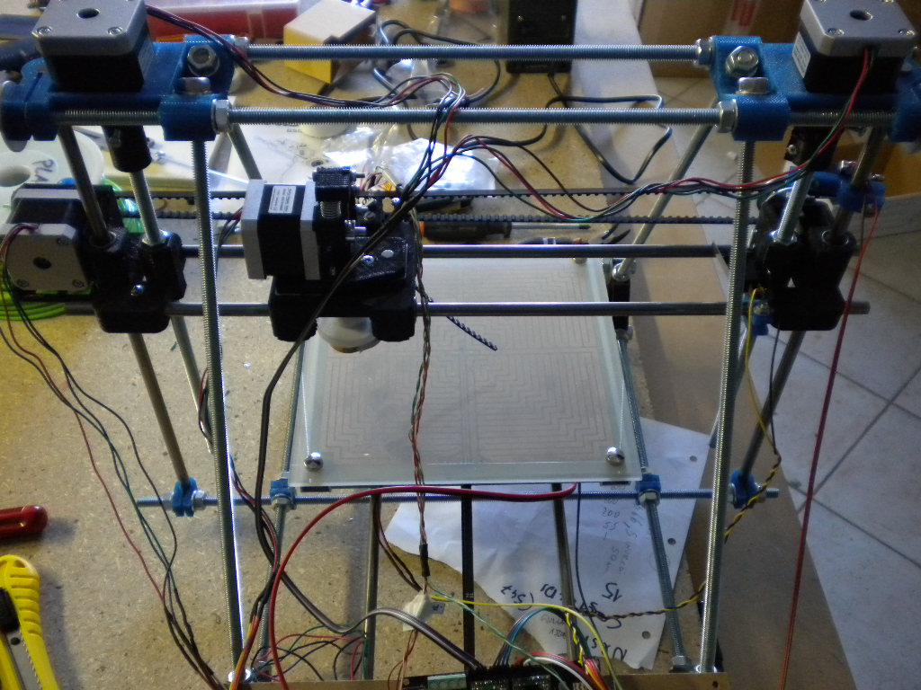
La foto (chiamiamola così  ) è troppo sfuocata per capirci qualcosa.
Comunque i pin 16 e 19 sarebbero sul chip quadrato nero saldato sul pololu, non sulla megatronics.
Vedi qui: [reprap.org]
I pin che ci interessano sono gli ultimi due a destra della basetta.
ciao
Eugenio
) è troppo sfuocata per capirci qualcosa.Comunque i pin 16 e 19 sarebbero sul chip quadrato nero saldato sul pololu, non sulla megatronics.
Vedi qui: [reprap.org]
I pin che ci interessano sono gli ultimi due a destra della basetta.
ciao
Eugenio
|
Re: Prime prove e primi test April 15, 2013 10:15AM |
Registered: 11 years ago Posts: 108 |
Grazie per dedicarmi del tempo!Per prima cosa!!!! I pin 7 e 8 li ho trovati ed ipotizzo anche i 16 e 19. Devo provare a metterli in relazione tra loro 7/16 e 8/19 e faccio la rilevazione con il multimetro? e per k'asse Z cosa devo fare? anche lì ho il solito problema!
Grazie e buona giornata!
Inco
I pin 7 e 8 li ho trovati ed ipotizzo anche i 16 e 19. Devo provare a metterli in relazione tra loro 7/16 e 8/19 e faccio la rilevazione con il multimetro? e per k'asse Z cosa devo fare? anche lì ho il solito problema!Grazie e buona giornata!
Inco
|
Re: Prime prove e primi test April 16, 2013 01:54AM |
Registered: 11 years ago Posts: 67 |
Ora che hai trovato i pin 7 e 8 puoi ignorare gli altri, che servivano sono per verifica.
Devi controllare con un multimetro lo stato del pin 8 (DIR) che durante il movimento dei motori non deve essere sempre a 5V o 0V, in pratica deve cambiare stato quando il motore dovrebbe cambiare verso di rotazione.
Se questo accade, vuol dire che il problema è altrove, se invece rimane sempre fisso significa che c'e' un problema sul micro o sul firmware.
|
Re: Prime prove e primi test April 18, 2013 12:42PM |
Registered: 11 years ago Posts: 108 |
|
Re: Prime prove e primi test April 19, 2013 06:27AM |
Registered: 11 years ago Posts: 67 |
|
Re: Prime prove e primi test April 19, 2013 07:00AM |
Registered: 11 years ago Posts: 67 |
|
Re: Prime prove e primi test April 21, 2013 06:05AM |
Registered: 11 years ago Posts: 108 |
In questi giorni ho avuto un pò da fare con il lavoro, ma stamattina mi ci sono messo sù a studiarci un pò ed ho fatto qualche prova. Risultato: nulla di fatto. Nel conf.h ho controllato la sezione relativa al mechanical settings (che riporto in allegato a fine post) ma non mi sembra di aver letto qualcosa inerente al mio problema, comunque ho provato a fare qualche variazione ma senza risultato. Il problema potrebbe essere in una altra sezione diversa del conf.h? Tipo in conf_adv.h? Escludo il software per la gestione di stampa, dato che ho provato sia repetier host che pronterface...
Allegato:
//===========================================================================
//=============================Mechanical Settings===========================
//===========================================================================
// Uncomment the following line to enable CoreXY kinematics
// #define COREXY
// corse Endstop Settings
#define ENDSTOPPULLUPS // Comment this out (using // at the start of the line) to disable the endstop pullup resistors
//#ifndef ENDSTOPPULLUPS
// // fine Enstop settings: Individual Pullups. will be ignord if ENDSTOPPULLUPS is defined
// #define ENDSTOPPULLUP_XMAX
// #define ENDSTOPPULLUP_YMAX
// #define ENDSTOPPULLUP_ZMAX
// #define ENDSTOPPULLUP_XMIN
// #define ENDSTOPPULLUP_YMIN
// //#define ENDSTOPPULLUP_ZMIN
//#endif
#ifdef ENDSTOPPULLUPS
// #define ENDSTOPPULLUP_XMAX
// #define ENDSTOPPULLUP_YMAX
// #define ENDSTOPPULLUP_ZMAX
#define ENDSTOPPULLUP_XMIN
#define ENDSTOPPULLUP_YMIN
#define ENDSTOPPULLUP_ZMIN
#endif
// The pullups are needed if you directly connect a mechanical endswitch between the signal and ground pins.
const bool X_ENDSTOPS_INVERTING = false; // set to true to invert the logic of the endstops.
const bool Y_ENDSTOPS_INVERTING = false; // set to true to invert the logic of the endstops.
const bool Z_ENDSTOPS_INVERTING = false; // set to true to invert the logic of the endstops.
#define DISABLE_MAX_ENDSTOPS
// For Inverting Stepper Enable Pins (Active Low) use 0, Non Inverting (Active High) use 1
#define X_ENABLE_ON 0
#define Y_ENABLE_ON 0
#define Z_ENABLE_ON 0
#define E_ENABLE_ON 0 // For all extruders
// Disables axis when it's not being used.
#define DISABLE_X false
#define DISABLE_Y false
#define DISABLE_Z false
#define DISABLE_E false // For all extruders
#define INVERT_X_DIR false // for Mendel set to false, for Orca set to true
#define INVERT_Y_DIR false // for Mendel set to true, for Orca set to false
#define INVERT_Z_DIR true // for Mendel set to false, for Orca set to true
#define INVERT_E0_DIR false // for direct drive extruder v9 set to true, for geared extruder set to false
#define INVERT_E1_DIR false // for direct drive extruder v9 set to true, for geared extruder set to false
#define INVERT_E2_DIR false // for direct drive extruder v9 set to true, for geared extruder set to false
// ENDSTOP SETTINGS:
// Sets direction of endstops when homing; 1=MAX, -1=MIN
#define X_HOME_DIR -1
#define Y_HOME_DIR -1
#define Z_HOME_DIR 1
#define min_software_endstops false //If true, axis won't move to coordinates less than HOME_POS.
#define max_software_endstops false //If true, axis won't move to coordinates greater than the defined lengths below.
// Travel limits after homing
#define X_MAX_POS 210
#define X_MIN_POS 0
#define Y_MAX_POS 150
#define Y_MIN_POS 0
#define Z_MAX_POS 110
#define Z_MIN_POS 0
#define X_MAX_LENGTH (X_MAX_POS - X_MIN_POS)
#define Y_MAX_LENGTH (Y_MAX_POS - Y_MIN_POS)
#define Z_MAX_LENGTH (Z_MAX_POS - Z_MIN_POS)
// The position of the homing switches
//#define MANUAL_HOME_POSITIONS // If defined, MANUAL_*_HOME_POS below will be used
//#define BED_CENTER_AT_0_0 // If defined, the center of the bed is at (X=0, Y=0)
//Manual homing switch locations:
#define MANUAL_X_HOME_POS 0
#define MANUAL_Y_HOME_POS 0
#define MANUAL_Z_HOME_POS 0
//// MOVEMENT SETTINGS
#define NUM_AXIS 4 // The axis order in all axis related arrays is X, Y, Z, E
#define HOMING_FEEDRATE {2000, 2000, 100, 0} // set the homing speeds (mm/min)
// default settings
#define DEFAULT_AXIS_STEPS_PER_UNIT {80,80,2560,95.62841530054645} // X, Y, Z, E default steps per unit for The Future Is 3D, Inc. For no direct drive use value like (x,x,x,750)
#define DEFAULT_MAX_FEEDRATE {500, 500, 5, 45} // (mm/sec)
#define DEFAULT_MAX_ACCELERATION {5000,5000,50,5000} // X, Y, Z, E maximum start speed for accelerated moves. E default values are good for skeinforge 40+, for older versions raise them a lot.
#define DEFAULT_ACCELERATION 3000 // X, Y, Z and E max acceleration in mm/s^2 for printing moves
#define DEFAULT_RETRACT_ACCELERATION 3000 // X, Y, Z and E max acceleration in mm/s^2 for r retracts
// Offset of the extruders (uncomment if using more than one and relying on firmware to position when changing).
// The offset has to be X=0, Y=0 for the extruder 0 hotend (default extruder).
// For the other hotends it is their distance from the extruder 0 hotend.
// #define EXTRUDER_OFFSET_X {0.0, 20.00} // (in mm) for each extruder, offset of the hotend on the X axis
// #define EXTRUDER_OFFSET_Y {0.0, 5.00} // (in mm) for each extruder, offset of the hotend on the Y axis
// The speed change that does not require acceleration (i.e. the software might assume it can be done instanteneously)
#define DEFAULT_XYJERK 20.0 // (mm/sec)
#define DEFAULT_ZJERK 0.4 // (mm/sec)
#define DEFAULT_EJERK 5.0 // (mm/sec)
Grazie ancora, buona domenica.
Inco

Sorry, only registered users may post in this forum.