Merakit printer reprap/restrap delta jenis Kossel Mini
Posted by ryannining
|
Merakit printer reprap/restrap delta jenis Kossel Mini February 04, 2016 08:33AM |
Registered: 9 years ago Posts: 281 |
Seperti biasa, printer reprap memang sangat bebas dalam hal interpretasi bagaimana merakitnya. Kebetulan saya lebih suka sekrup + dibanding hex/L stainless, karena lebih mudah proses rakitnya.
Part2 yang dibutuhkan, (tersedia di tokopedia).
Part kossel K800
Roda nylon 9
2020 Alum 1
Carbon tube Kossel 1
Magnet 12
Ball joint 12
KosselPart 1
Bed kaca 1
Nozle 1
hotbox 1
throat 1
ptfe tube 1
colermaster 1
pushfit 1 5mm
f623z 6
608z 1
pemanas 1
ntc 1
mk8 gear 1
motor 4
mega2560 1
ramps 1
motor deriver 4
Power supply 1
Enstop Sw 3
Display 1
Pertama, yg dilakukan adalah membor semua aluminium, dengan posisi bor adalah lubang sekrup pada part plastik. Bor memakai mata 3.5mm kemudian ditap M4. Kalo pesen di toko saya bisa minta diborkan sekalian, karena harus pake bor duduk biar pas.
Kemudian untuk motor, karena aslinya harus pake sekrup m3 hex/L menyusahkan, saya si biasa dengan cara ini:
- ganti baut motor 2 unit bagian bawah dengan m3 yg panjang sampai depan, trus di mur depannya.
Untuk tiang tinggi tiap sudut memakai sekrup M4 seperti ini
Untuk slider carriagenya, karena adanya nylon yg lebih tipis ,saya pake 2 buah seperti ini. Untuk sekrup2 ke dudukan saya bor dulu pake bor 2.5mm
Bagian belakang slidernya dicable ties, supaya sekrupnya tidak miring.
BERSAMBUNG
Part2 yang dibutuhkan, (tersedia di tokopedia).
Part kossel K800
Roda nylon 9
2020 Alum 1
Carbon tube Kossel 1
Magnet 12
Ball joint 12
KosselPart 1
Bed kaca 1
Nozle 1
hotbox 1
throat 1
ptfe tube 1
colermaster 1
pushfit 1 5mm
f623z 6
608z 1
pemanas 1
ntc 1
mk8 gear 1
motor 4
mega2560 1
ramps 1
motor deriver 4
Power supply 1
Enstop Sw 3
Display 1
Pertama, yg dilakukan adalah membor semua aluminium, dengan posisi bor adalah lubang sekrup pada part plastik. Bor memakai mata 3.5mm kemudian ditap M4. Kalo pesen di toko saya bisa minta diborkan sekalian, karena harus pake bor duduk biar pas.
Kemudian untuk motor, karena aslinya harus pake sekrup m3 hex/L menyusahkan, saya si biasa dengan cara ini:


- ganti baut motor 2 unit bagian bawah dengan m3 yg panjang sampai depan, trus di mur depannya.
Untuk tiang tinggi tiap sudut memakai sekrup M4 seperti ini


Untuk slider carriagenya, karena adanya nylon yg lebih tipis ,saya pake 2 buah seperti ini. Untuk sekrup2 ke dudukan saya bor dulu pake bor 2.5mm


Bagian belakang slidernya dicable ties, supaya sekrupnya tidak miring.

BERSAMBUNG
|
Re: Merakit printer reprap/restrap delta jenis Kossel Mini February 04, 2016 08:37AM |
Registered: 9 years ago Posts: 281 |
Menyiapkan BED
Pembuatan dudukan BED ini dari dulu bikin saya pusing. Namun cara ini (mungkin bukan cara terakhir, bebas si) adalah cara termudah dalam hal pembuatan dan metode pasang dan lepas bednya.
Untuk Printer DELTA, saya selalu membuat bed tidak bisa diatur dan duduk dengan solid. Kali ini dia duduk solid diatas kotak gabus.
- Ukur tempat gabus harus dipotong, harus bener2 fit dengan posisi segitiga
- Potong gabus tadi, dan test apakah sesak, kalo longgar harus diulangi motong baru
- gunakan lem khusus gabus untuk menempelkan kaca ke gabus
Hore, sudah jadi, mudah dilepas dan cukup solid.
BERSAMBUNG
Pembuatan dudukan BED ini dari dulu bikin saya pusing. Namun cara ini (mungkin bukan cara terakhir, bebas si) adalah cara termudah dalam hal pembuatan dan metode pasang dan lepas bednya.
Untuk Printer DELTA, saya selalu membuat bed tidak bisa diatur dan duduk dengan solid. Kali ini dia duduk solid diatas kotak gabus.
- Ukur tempat gabus harus dipotong, harus bener2 fit dengan posisi segitiga
- Potong gabus tadi, dan test apakah sesak, kalo longgar harus diulangi motong baru
- gunakan lem khusus gabus untuk menempelkan kaca ke gabus
Hore, sudah jadi, mudah dilepas dan cukup solid.


BERSAMBUNG
|
Re: Merakit printer reprap/restrap delta jenis Kossel Mini February 04, 2016 08:49AM |
Registered: 9 years ago Posts: 281 |
Memasang semua magnet memakai ALTECO, kemudian sekrupkan ke masing2 carriage.
Memasang part extruder seperti ini
Untuk dudukan motor extruder, kali ini saya letakkan diatas, profil aluminium dibor 3.5mm dan dibikin drat m4
MENYIAPKAN EFFECTOR HOT END DLL
Bahan:
1 fan coolermaster heatsink
1 nozzle hot box dan throat sudah dipasang.
1 teflon tube 1m
1 pushfit 5mm
M4 mur
Pasang M4 mur ke teflon tube, secukupnya sampai kira2 5cm masuk
Letakkan M4 mur tsb di tengah heatsink coolermaster dan tekuk sirip2 sekitarnya.
Masukkan hotend ke teflon. Tekuk sirip2 disekitar throat dan, keluarkan lagi htendnya. Bikin drat M7 pada sirip2 yg ditekuk deket troat tadi.
Lepas nozzle, ulirkan hotend/throat ke sirip yg sudah didrat tadi, sampai terlihat tubenya nyanmpe ujung throatnya di dalam hotbox.
Pasang dan kencangkan nozzle. Kalo perlu kasi alteco disekitar throat yg ngedrat ke sirip.
Pasang magnet pada plastic part effector. Kasi dasaran kertas biar gampang nempel. Bikin drat M3 pada lubang kedua di sirip, ini nanti akan disekrup ke plastic part
Effector dah jadi, ukur secukupnya teflon dan potong, pasang pushfit 5mm di ujungnya dan sekrupkan ke extruder.
BERSAMBUNG


Memasang part extruder seperti ini

Untuk dudukan motor extruder, kali ini saya letakkan diatas, profil aluminium dibor 3.5mm dan dibikin drat m4

MENYIAPKAN EFFECTOR HOT END DLL
Bahan:
1 fan coolermaster heatsink
1 nozzle hot box dan throat sudah dipasang.
1 teflon tube 1m
1 pushfit 5mm
M4 mur
Pasang M4 mur ke teflon tube, secukupnya sampai kira2 5cm masuk
Letakkan M4 mur tsb di tengah heatsink coolermaster dan tekuk sirip2 sekitarnya.
Masukkan hotend ke teflon. Tekuk sirip2 disekitar throat dan, keluarkan lagi htendnya. Bikin drat M7 pada sirip2 yg ditekuk deket troat tadi.
Lepas nozzle, ulirkan hotend/throat ke sirip yg sudah didrat tadi, sampai terlihat tubenya nyanmpe ujung throatnya di dalam hotbox.
Pasang dan kencangkan nozzle. Kalo perlu kasi alteco disekitar throat yg ngedrat ke sirip.


Pasang magnet pada plastic part effector. Kasi dasaran kertas biar gampang nempel. Bikin drat M3 pada lubang kedua di sirip, ini nanti akan disekrup ke plastic part


Effector dah jadi, ukur secukupnya teflon dan potong, pasang pushfit 5mm di ujungnya dan sekrupkan ke extruder.
BERSAMBUNG
|
Re: Merakit printer reprap/restrap delta jenis Kossel Mini February 05, 2016 09:31AM |
Registered: 9 years ago Posts: 281 |

Lanjut, sekarang kita pasang belt puley, tempat belt berputar arah diatas.

Kemudian saya siapkan belt, kebetulan, saya memakai belt yg dibagi2, iseng aja, hemat.

Pasang belt seperti ini.

Untuk alat pemotong belt bisa download di folder mk2b namanya beltcutmxl.stl , barusan saya upload.
hasil sesudah dipasang semua beltnya.

Untuk lengannya cara bikinnya ya simpel aja pake lem, intinya usahakan sama semua panjangnya. nanti diukur panjangnya, dikurangi 10mm itu adalah seting untuk ROD LENGTH.
Edited 1 time(s). Last edit at 02/05/2016 09:32AM by ryannining.
|
Re: Merakit printer reprap/restrap delta jenis Kossel Mini February 05, 2016 09:42AM |
Registered: 9 years ago Posts: 281 |
Pemasangan kabel dan dudukan buat arduino.
Kali ini saya pake teknik repstrap, pake apa aja yg ada intinya bikin dudukan arduino+ramps, supaya mudah diakses untuk colok USB dan powernya.
Kemudian saya pasang kabel 4 pin ke semua motor. Khusus motor XYZ, kabelnya pendek aja, biar rapi.
Dari kabel 4 pin, yg perlu dituker adalah kabel biru dan hitam saat disambung ke kabel motor.
Sesudah terpasang semua
Tinggi dari mega ramps, ini akan nyundul gabus yg nempel di bed kaca, karenanya pake korek, kita bakar gabus yg diatas mega ramps supaya muat.
Rapikan pake kabel ties.
BERSAMBUNG
Kali ini saya pake teknik repstrap, pake apa aja yg ada intinya bikin dudukan arduino+ramps, supaya mudah diakses untuk colok USB dan powernya.


Kemudian saya pasang kabel 4 pin ke semua motor. Khusus motor XYZ, kabelnya pendek aja, biar rapi.
Dari kabel 4 pin, yg perlu dituker adalah kabel biru dan hitam saat disambung ke kabel motor.

Sesudah terpasang semua

Tinggi dari mega ramps, ini akan nyundul gabus yg nempel di bed kaca, karenanya pake korek, kita bakar gabus yg diatas mega ramps supaya muat.

Rapikan pake kabel ties.

BERSAMBUNG
|
Re: Merakit printer reprap/restrap delta jenis Kossel Mini February 08, 2016 09:31AM |
Registered: 9 years ago Posts: 281 |
Pasang / solder kabel panjang ke endstop bagian normally closed.
Pasang pin 2 ke masing2 ujung kabel endstop .
Saya juga merevisi dudukan kmaren menjadi pake akrilik.yg dilem plastik tembak.
Dudukan kaca juga direvisi, karena butuh space didalam untuk kabel2 yg versi kmarin kena kabel2. Besok paling saya cari paper clip yg besar, biar bisa ngeklip kaca ke profil aluminiumnya.
Sekarang sedang test print perdana.
Berikut file2 firmware bisa didownload disini.
Setting rod length saya pakai 210mm
Rod radius 99.5
Step/mm untuk motor xyz 175.1505 (motor .9deg puly mxl 18teeth microstep 1/16)
Step/mm extruder 304
Untuk Zmax kalo ngikut panduan diatas, kira2 di 214-216
http://resin.tokoled.net/down/k800
Ups, tambahan saat membuat hotend, teflon tube yg sudah dikasi mur M4 ditengahnya harus dibor dulu dengan mata 2mm, karena saat didrat sekrup tsb, lubangnya mengecil.
Update hasil cetak
Lumayan hasilnya. Layer 0.15 tak skala znya aja 1.5x la aslinya si gurita gepeng.
=====================================
KALIBRASI ZMAX
1. Pastikan step/mm sudah benar
2. Buka eeprom setting, masukkan ZMAX dikira2 jarak nozzle ke kaca, dilebihkan 20mm
3. Secara manual klik HOME
4. Klik Z- sampai nozzle nyentuh kaca.
5. Cek sisa Z di tampilan repetier. Misal sisa 5
6. Masuk ke eeprom setting, kurangi nilai ZMAX dengan 5
KALIBRASI ROD RADIUS
Kalau memakai model roller yg berbeda, maka mungkin rod radius bisa beda. Cara kalibrasinya,
1. Kira2 rod radius misal 100
2. pasang paku panjang di salah satu magnet mengarah ke kaca.
3. Pasang penggaris mika di bawah, gerakkkan dengan repetier Z- sampai paku menunjuk angka di penggaris.
4. Gerakkan ke arah bebas, misal X+10 sampai 5x jadi harusnya geser 50mm, cek di penggaris
Kalo sudah pas, lewati , berarti sudah benar
5. Kalau gesernya kurang dari 50mm ,maka rod radius harus ditambahi, tambahkan dikit2 saja, misal nambah 1-3. Buka eeprom setting, kurangi, save. Kemudian klik HOME dan ulangi lagi mulai nomor 3
6. Kalau gesernya lebih dari 50mm ,maka rod radius harus dikurangi. Buka eeprom setting, kurangi, save. Kemudian klik HOME dan ulangi lagi mulai nomor 3
Proses kalibrasi ini berlaku untuk semua printer DELTA.
Edited 3 time(s). Last edit at 02/08/2016 10:34AM by ryannining.

Pasang pin 2 ke masing2 ujung kabel endstop .

Saya juga merevisi dudukan kmaren menjadi pake akrilik.yg dilem plastik tembak.

Dudukan kaca juga direvisi, karena butuh space didalam untuk kabel2 yg versi kmarin kena kabel2. Besok paling saya cari paper clip yg besar, biar bisa ngeklip kaca ke profil aluminiumnya.
Sekarang sedang test print perdana.
Berikut file2 firmware bisa didownload disini.
Setting rod length saya pakai 210mm
Rod radius 99.5
Step/mm untuk motor xyz 175.1505 (motor .9deg puly mxl 18teeth microstep 1/16)
Step/mm extruder 304
Untuk Zmax kalo ngikut panduan diatas, kira2 di 214-216
http://resin.tokoled.net/down/k800
Ups, tambahan saat membuat hotend, teflon tube yg sudah dikasi mur M4 ditengahnya harus dibor dulu dengan mata 2mm, karena saat didrat sekrup tsb, lubangnya mengecil.
Update hasil cetak

Lumayan hasilnya. Layer 0.15 tak skala znya aja 1.5x la aslinya si gurita gepeng.
=====================================
KALIBRASI ZMAX
1. Pastikan step/mm sudah benar
2. Buka eeprom setting, masukkan ZMAX dikira2 jarak nozzle ke kaca, dilebihkan 20mm
3. Secara manual klik HOME
4. Klik Z- sampai nozzle nyentuh kaca.
5. Cek sisa Z di tampilan repetier. Misal sisa 5
6. Masuk ke eeprom setting, kurangi nilai ZMAX dengan 5
KALIBRASI ROD RADIUS
Kalau memakai model roller yg berbeda, maka mungkin rod radius bisa beda. Cara kalibrasinya,
1. Kira2 rod radius misal 100
2. pasang paku panjang di salah satu magnet mengarah ke kaca.
3. Pasang penggaris mika di bawah, gerakkkan dengan repetier Z- sampai paku menunjuk angka di penggaris.
4. Gerakkan ke arah bebas, misal X+10 sampai 5x jadi harusnya geser 50mm, cek di penggaris
Kalo sudah pas, lewati , berarti sudah benar
5. Kalau gesernya kurang dari 50mm ,maka rod radius harus ditambahi, tambahkan dikit2 saja, misal nambah 1-3. Buka eeprom setting, kurangi, save. Kemudian klik HOME dan ulangi lagi mulai nomor 3
6. Kalau gesernya lebih dari 50mm ,maka rod radius harus dikurangi. Buka eeprom setting, kurangi, save. Kemudian klik HOME dan ulangi lagi mulai nomor 3
Proses kalibrasi ini berlaku untuk semua printer DELTA.
Edited 3 time(s). Last edit at 02/08/2016 10:34AM by ryannining.
|
Re: Merakit printer reprap/restrap delta jenis Kossel Mini March 01, 2016 02:27AM |
Registered: 8 years ago Posts: 24 |
Gan antara konektor power arduino dengan konektor hijau di ramps (diatasnya) perlu disolder kabel jumper ga?Tq
>>>> Dapat jawaban dari agan ryan via WA, jawabannya > tidak, kabel power supply yang di modif untuk nyambung
ke konektor hijau di ramps.
Makasi gan
Edited 1 time(s). Last edit at 03/01/2016 10:31PM by mantripa.
>>>> Dapat jawaban dari agan ryan via WA, jawabannya > tidak, kabel power supply yang di modif untuk nyambung
ke konektor hijau di ramps.
Makasi gan
Edited 1 time(s). Last edit at 03/01/2016 10:31PM by mantripa.
|
Re: Merakit printer reprap/restrap delta jenis Kossel Mini March 01, 2016 09:57PM |
Registered: 8 years ago Posts: 24 |
|
Re: Merakit printer reprap/restrap delta jenis Kossel Mini March 01, 2016 10:04PM |
Registered: 8 years ago Posts: 24 |
|
Re: Merakit printer reprap/restrap delta jenis Kossel Mini March 01, 2016 10:20PM |
Registered: 8 years ago Posts: 24 |
Inductive sensor, yg ini harus belajar banyak kayaknya, untuk sementara hanya untuk mencari posisi
penempatan dudukan yg paling dekat dengan hotend, semoga nanti bisa jalan
penempatan dudukan yg paling dekat dengan hotend, semoga nanti bisa jalan
|
Re: Merakit printer reprap/restrap delta jenis Kossel Mini March 01, 2016 10:27PM |
Registered: 8 years ago Posts: 24 |
|
Re: Merakit printer reprap/restrap delta jenis Kossel Mini March 02, 2016 08:21PM |
Registered: 9 years ago Posts: 281 |
|
Re: Merakit printer reprap/restrap delta jenis Kossel Mini March 03, 2016 05:31AM |
Registered: 8 years ago Posts: 24 |
|
Re: Merakit printer reprap/restrap delta jenis Kossel Mini March 03, 2016 07:56AM |
Registered: 9 years ago Posts: 281 |
Kalo di CoreXZ, yg saya lakukan seperti ini:
Posisikan nozzle nempel bed.
Ttrus atur sensor sedekat mungkin kira2 mungkin 1-2mm diatas bed.
Ntar di configuration harus aktifkan feature_autolevel (asumsi firmware repetier)
Upload firmware
Ntar di eeprom setting, di setting
- zprobe offset x y sesuai posisi, kira2 aja
- z probe height antara 0 sd 1, dicoba2 si
- z probe to bed = 0
posisi x1,y1,x2,y2,x3,y3 diisi kira2 untuk delta mungkin adalah posisi 3 titik deket tiang.
|
Re: Merakit printer reprap/restrap delta jenis Kossel Mini March 05, 2016 06:04AM |
Registered: 8 years ago Posts: 24 |
|
Re: Merakit printer reprap/restrap delta jenis Kossel Mini March 07, 2016 02:04AM |
Registered: 8 years ago Posts: 24 |
|
Re: Merakit printer reprap/restrap delta jenis Kossel Mini March 07, 2016 06:22AM |
Registered: 9 years ago Posts: 281 |
|
Re: Merakit printer reprap/restrap delta jenis Kossel Mini March 13, 2016 03:31AM |
Registered: 8 years ago Posts: 24 |
Autobed leveling udah jalan [youtu.be]
cuma sampai deket tiang Z macet, ga tau kenapa...
settingan Z probe offsetnya x-19 y0 z-1.0
Printable radius 70, ini kalo dirubah ke lebih besar misal 80, lokasi macetnya berubah
Probe radiusnya, printable radius - 20
lokasi probe pointnya ga mau merata,, lebih kearah kanan kayaknya
Ada yang bisa bantu gan......?
|
Re: Merakit printer reprap/restrap delta jenis Kossel Mini March 13, 2016 04:14AM |
Registered: 9 years ago Posts: 281 |
Coba dishare firwarenya sourcenya ntar saya ikut bikin kalo stok arduinonya dah datang, moga seminggu. Sekalian Roller yg bener2 memang buat sliding halus juga ada dalam paket dari cina. Ama ada motor 2 stepper khusus dg gear, buat rist bikin extruder non bowden compact buat delta.
Ama LASER 2.5W WOW mantap ini bisa motong akrilik 3mm
yg minat PM atau whatsapp aja ke
083842051743 nining
083838461040 ryan
Ama LASER 2.5W WOW mantap ini bisa motong akrilik 3mm

yg minat PM atau whatsapp aja ke
083842051743 nining
083838461040 ryan
|
Re: Merakit printer reprap/restrap delta jenis Kossel Mini March 14, 2016 11:48PM |
Registered: 8 years ago Posts: 24 |
Saya pake Marlin...
#ifndef CONFIGURATION_H
#define CONFIGURATION_H
#include "boards.h"
//===========================================================================
//============================= Getting Started =============================
//===========================================================================
/*
Here are some standard links for getting your machine calibrated:
* [reprap.org]
* [youtu.be]
* [calculator.josefprusa.cz]
* [reprap.org]
* [www.thingiverse.com]
* [sites.google.com]
* [www.thingiverse.com]
*/
// This configuration file contains the basic settings.
// Advanced settings can be found in Configuration_adv.h
// BASIC SETTINGS: select your board type, temperature sensor type, axis scaling, and endstop configuration
//===========================================================================
//============================= DELTA Printer ===============================
//===========================================================================
// For a Delta printer replace the configuration files with the files in the
// example_configurations/delta directory.
//
//===========================================================================
//============================= SCARA Printer ===============================
//===========================================================================
// For a Delta printer replace the configuration files with the files in the
// example_configurations/SCARA directory.
//
// User-specified version info of this build to display in [Pronterface, etc] terminal window during
// startup. Implementation of an idea by Prof Braino to inform user that any changes made to this
// build by the user have been successfully uploaded into firmware.
#define STRING_VERSION "1.0.2"
#define STRING_URL "reprap.org"
#define STRING_VERSION_CONFIG_H __DATE__ " " __TIME__ // build date and time
#define STRING_CONFIG_H_AUTHOR "(none, default config)" // Who made the changes.
#define STRING_SPLASH_LINE1 "v" STRING_VERSION // will be shown during bootup in line 1
//#define STRING_SPLASH_LINE2 STRING_VERSION_CONFIG_H // will be shown during bootup in line2
// SERIAL_PORT selects which serial port should be used for communication with the host.
// This allows the connection of wireless adapters (for instance) to non-default port pins.
// Serial port 0 is still used by the Arduino bootloader regardless of this setting.
#define SERIAL_PORT 0
// This determines the communication speed of the printer
#define BAUDRATE 115200
// This enables the serial port associated to the Bluetooth interface
//#define BTENABLED // Enable BT interface on AT90USB devices
// The following define selects which electronics board you have.
// Please choose the name from boards.h that matches your setup
#define MOTHERBOARD BOARD_RAMPS_13_EFB
#ifndef MOTHERBOARD
#define MOTHERBOARD BOARD_RAMPS_13_EFB
#endif
// Define this to set a custom name for your generic Mendel,
#define CUSTOM_MENDEL_NAME "Mini Kossel"
// Define this to set a unique identifier for this printer, (Used by some programs to differentiate between machines)
// You can use an online service to generate a random UUID. (eg [www.uuidgenerator.net])
// #define MACHINE_UUID "00000000-0000-0000-0000-000000000000"
// This defines the number of extruders
#define EXTRUDERS 1
//// The following define selects which power supply you have. Please choose the one that matches your setup
// 1 = ATX
// 2 = X-Box 360 203Watts (the blue wire connected to PS_ON and the red wire to VCC)
#define POWER_SUPPLY 1
// Define this to have the electronics keep the power supply off on startup. If you don't know what this is leave it.
// #define PS_DEFAULT_OFF
//===========================================================================
//============================== Delta Settings =============================
//===========================================================================
// Enable DELTA kinematics and most of the default configuration for Deltas
#define DELTA
// Make delta curves from many straight lines (linear interpolation).
// This is a trade-off between visible corners (not enough segments)
// and processor overload (too many expensive sqrt calls).
#define DELTA_SEGMENTS_PER_SECOND 200
// NOTE NB all values for DELTA_* values MUST be floating point, so always have a decimal point in them
// Center-to-center distance of the holes in the diagonal push rods.
#define DELTA_DIAGONAL_ROD 210.0 // mm
// Horizontal offset from middle of printer to smooth rod center.
#define DELTA_SMOOTH_ROD_OFFSET 150.5 // mm
// Horizontal offset of the universal joints on the end effector.
#define DELTA_EFFECTOR_OFFSET 35.0 // mm
// Horizontal offset of the universal joints on the carriages.
#define DELTA_CARRIAGE_OFFSET 30.0 // mm
// Horizontal distance bridged by diagonal push rods when effector is centered.
#define DELTA_RADIUS 99.5 //(DELTA_SMOOTH_ROD_OFFSET-DELTA_EFFECTOR_OFFSET-DELTA_CARRIAGE_OFFSET)
// Print surface diameter/2 minus unreachable space (avoid collisions with vertical towers).
#define DELTA_PRINTABLE_RADIUS 70
#define SIN_60 0.8660254037844386
#define COS_60 0.5
#define DELTA_TOWER1_X -SIN_60*DELTA_RADIUS
#define DELTA_TOWER1_Y -COS_60*DELTA_RADIUS
#define DELTA_TOWER2_X SIN_60*DELTA_RADIUS
#define DELTA_TOWER2_Y -COS_60*DELTA_RADIUS
#define DELTA_TOWER3_X 0.0
#define DELTA_TOWER3_Y DELTA_RADIUS
#define DELTA_DIAGONAL_ROD_2 pow(DELTA_DIAGONAL_ROD,2)
//===========================================================================
//============================= Thermal Settings ============================
//===========================================================================
//
//--NORMAL IS 4.7kohm PULLUP!-- 1kohm pullup can be used on hotend sensor, using correct resistor and table
//
//// Temperature sensor settings:
// -2 is thermocouple with MAX6675 (only for sensor 0)
// -1 is thermocouple with AD595
// 0 is not used
// 1 is 100k thermistor - best choice for EPCOS 100k (4.7k pullup)
// 2 is 200k thermistor - ATC Semitec 204GT-2 (4.7k pullup)
// 3 is Mendel-parts thermistor (4.7k pullup)
// 4 is 10k thermistor !! do not use it for a hotend. It gives bad resolution at high temp. !!
// 5 is 100K thermistor - ATC Semitec 104GT-2 (Used in ParCan & J-Head) (4.7k pullup)
// 6 is 100k EPCOS - Not as accurate as table 1 (created using a fluke thermocouple) (4.7k pullup)
// 7 is 100k Honeywell thermistor 135-104LAG-J01 (4.7k pullup)
// 71 is 100k Honeywell thermistor 135-104LAF-J01 (4.7k pullup)
// 8 is 100k 0603 SMD Vishay NTCS0603E3104FXT (4.7k pullup)
// 9 is 100k GE Sensing AL03006-58.2K-97-G1 (4.7k pullup)
// 10 is 100k RS thermistor 198-961 (4.7k pullup)
// 11 is 100k beta 3950 1% thermistor (4.7k pullup)
// 12 is 100k 0603 SMD Vishay NTCS0603E3104FXT (4.7k pullup) (calibrated for Makibox hot bed)
// 13 is 100k Hisens 3950 1% up to 300°C for hotend "Simple ONE " & "Hotend "All In ONE"
// 20 is the PT100 circuit found in the Ultimainboard V2.x
// 60 is 100k Maker's Tool Works Kapton Bed Thermistor beta=3950
//
// 1k ohm pullup tables - This is not normal, you would have to have changed out your 4.7k for 1k
// (but gives greater accuracy and more stable PID)
// 51 is 100k thermistor - EPCOS (1k pullup)
// 52 is 200k thermistor - ATC Semitec 204GT-2 (1k pullup)
// 55 is 100k thermistor - ATC Semitec 104GT-2 (Used in ParCan & J-Head) (1k pullup)
//
// 1047 is Pt1000 with 4k7 pullup
// 1010 is Pt1000 with 1k pullup (non standard)
// 147 is Pt100 with 4k7 pullup
// 110 is Pt100 with 1k pullup (non standard)
// 998 and 999 are Dummy Tables. They will ALWAYS read 25°C or the temperature defined below.
// Use it for Testing or Development purposes. NEVER for production machine.
// #define DUMMY_THERMISTOR_998_VALUE 25
// #define DUMMY_THERMISTOR_999_VALUE 100
#define TEMP_SENSOR_0 5
#define TEMP_SENSOR_1 0
#define TEMP_SENSOR_2 0
#define TEMP_SENSOR_3 0
#define TEMP_SENSOR_BED 0
// This makes temp sensor 1 a redundant sensor for sensor 0. If the temperatures difference between these sensors is to high the print will be aborted.
//#define TEMP_SENSOR_1_AS_REDUNDANT
#define MAX_REDUNDANT_TEMP_SENSOR_DIFF 5
// Actual temperature must be close to target for this long before M109 returns success
#define TEMP_RESIDENCY_TIME 10 // (seconds)
#define TEMP_HYSTERESIS 3 // (degC) range of +/- temperatures considered "close" to the target one
#define TEMP_WINDOW 1 // (degC) Window around target to start the residency timer x degC early.
// The minimal temperature defines the temperature below which the heater will not be enabled It is used
// to check that the wiring to the thermistor is not broken.
// Otherwise this would lead to the heater being powered on all the time.
#define HEATER_0_MINTEMP 5
#define HEATER_1_MINTEMP 5
#define HEATER_2_MINTEMP 5
#define HEATER_3_MINTEMP 5
#define BED_MINTEMP 5
// When temperature exceeds max temp, your heater will be switched off.
// This feature exists to protect your hotend from overheating accidentally, but *NOT* from thermistor short/failure!
// You should use MINTEMP for thermistor short/failure protection.
#define HEATER_0_MAXTEMP 275
#define HEATER_1_MAXTEMP 275
#define HEATER_2_MAXTEMP 275
#define HEATER_3_MAXTEMP 275
#define BED_MAXTEMP 150
// If your bed has low resistance e.g. .6 ohm and throws the fuse you can duty cycle it to reduce the
// average current. The value should be an integer and the heat bed will be turned on for 1 interval of
// HEATER_BED_DUTY_CYCLE_DIVIDER intervals.
//#define HEATER_BED_DUTY_CYCLE_DIVIDER 4
// If you want the M105 heater power reported in watts, define the BED_WATTS, and (shared for all extruders) EXTRUDER_WATTS
//#define EXTRUDER_WATTS (12.0*12.0/6.7) // P=I^2/R
//#define BED_WATTS (12.0*12.0/1.1) // P=I^2/R
//===========================================================================
//============================= PID Settings ================================
//===========================================================================
// PID Tuning Guide here: [reprap.org]
// Comment the following line to disable PID and enable bang-bang.
#define PIDTEMP
#define BANG_MAX 255 // limits current to nozzle while in bang-bang mode; 255=full current
#define PID_MAX BANG_MAX // limits current to nozzle while PID is active (see PID_FUNCTIONAL_RANGE below); 255=full current
#ifdef PIDTEMP
//#define PID_DEBUG // Sends debug data to the serial port.
//#define PID_OPENLOOP 1 // Puts PID in open loop. M104/M140 sets the output power from 0 to PID_MAX
//#define SLOW_PWM_HEATERS // PWM with very low frequency (roughly 0.125Hz=8s) and minimum state time of approximately 1s useful for heaters driven by a relay
//#define PID_PARAMS_PER_EXTRUDER // Uses separate PID parameters for each extruder (useful for mismatched extruders)
// Set/get with gcode: M301 E[extruder number, 0-2]
#define PID_FUNCTIONAL_RANGE 10 // If the temperature difference between the target temperature and the actual temperature
// is more then PID_FUNCTIONAL_RANGE then the PID will be shut off and the heater will be set to min/max.
#define PID_INTEGRAL_DRIVE_MAX PID_MAX //limit for the integral term
#define K1 0.95 //smoothing factor within the PID
// If you are using a pre-configured hotend then you can use one of the value sets by uncommenting it
// Ultimaker
#define DEFAULT_Kp 22.2
#define DEFAULT_Ki 1.08
#define DEFAULT_Kd 114
// MakerGear
// #define DEFAULT_Kp 7.0
// #define DEFAULT_Ki 0.1
// #define DEFAULT_Kd 12
// Mendel Parts V9 on 12V
// #define DEFAULT_Kp 63.0
// #define DEFAULT_Ki 2.25
// #define DEFAULT_Kd 440
#endif // PIDTEMP
//===========================================================================
//============================= PID > Bed Temperature Control ===============
//===========================================================================
// Select PID or bang-bang with PIDTEMPBED. If bang-bang, BED_LIMIT_SWITCHING will enable hysteresis
//
// Uncomment this to enable PID on the bed. It uses the same frequency PWM as the extruder.
// If your PID_dT is the default, and correct for your hardware/configuration, that means 7.689Hz,
// which is fine for driving a square wave into a resistive load and does not significantly impact you FET heating.
// This also works fine on a Fotek SSR-10DA Solid State Relay into a 250W heater.
// If your configuration is significantly different than this and you don't understand the issues involved, you probably
// shouldn't use bed PID until someone else verifies your hardware works.
// If this is enabled, find your own PID constants below.
//#define PIDTEMPBED
//
//#define BED_LIMIT_SWITCHING
// This sets the max power delivered to the bed, and replaces the HEATER_BED_DUTY_CYCLE_DIVIDER option.
// all forms of bed control obey this (PID, bang-bang, bang-bang with hysteresis)
// setting this to anything other than 255 enables a form of PWM to the bed just like HEATER_BED_DUTY_CYCLE_DIVIDER did,
// so you shouldn't use it unless you are OK with PWM on your bed. (see the comment on enabling PIDTEMPBED)
#define MAX_BED_POWER 255 // limits duty cycle to bed; 255=full current
//#define PID_BED_DEBUG // Sends debug data to the serial port.
#ifdef PIDTEMPBED
//120v 250W silicone heater into 4mm borosilicate (MendelMax 1.5+)
//from FOPDT model - kp=.39 Tp=405 Tdead=66, Tc set to 79.2, aggressive factor of .15 (vs .1, 1, 10)
#define DEFAULT_bedKp 10.00
#define DEFAULT_bedKi .023
#define DEFAULT_bedKd 305.4
//120v 250W silicone heater into 4mm borosilicate (MendelMax 1.5+)
//from pidautotune
// #define DEFAULT_bedKp 97.1
// #define DEFAULT_bedKi 1.41
// #define DEFAULT_bedKd 1675.16
// FIND YOUR OWN: "M303 E-1 C8 S90" to run autotune on the bed at 90 degreesC for 8 cycles.
#endif // PIDTEMPBED
//this prevents dangerous Extruder moves, i.e. if the temperature is under the limit
//can be software-disabled for whatever purposes by
#define PREVENT_DANGEROUS_EXTRUDE
//if PREVENT_DANGEROUS_EXTRUDE is on, you can still disable (uncomment) very long bits of extrusion separately.
#define PREVENT_LENGTHY_EXTRUDE
#define EXTRUDE_MINTEMP 140
#define EXTRUDE_MAXLENGTH (X_MAX_LENGTH+Y_MAX_LENGTH) //prevent extrusion of very large distances.
//===========================================================================
//============================= Thermal Runaway Protection ==================
//===========================================================================
/*
This is a feature to protect your printer from burn up in flames if it has
a thermistor coming off place (this happened to a friend of mine recently and
motivated me writing this feature).
The issue: If a thermistor come off, it will read a lower temperature than actual.
The system will turn the heater on forever, burning up the filament and anything
else around.
After the temperature reaches the target for the first time, this feature will
start measuring for how long the current temperature stays below the target
minus _HYSTERESIS (set_temperature - THERMAL_RUNAWAY_PROTECTION_HYSTERESIS).
If it stays longer than _PERIOD, it means the thermistor temperature
cannot catch up with the target, so something *may be* wrong. Then, to be on the
safe side, the system will he halt.
Bear in mind the count down will just start AFTER the first time the
thermistor temperature is over the target, so you will have no problem if
your extruder heater takes 2 minutes to hit the target on heating.
*/
// If you want to enable this feature for all your extruder heaters,
// uncomment the 2 defines below:
// Parameters for all extruder heaters
//#define THERMAL_RUNAWAY_PROTECTION_PERIOD 40 //in seconds
//#define THERMAL_RUNAWAY_PROTECTION_HYSTERESIS 4 // in degree Celsius
// If you want to enable this feature for your bed heater,
// uncomment the 2 defines below:
// Parameters for the bed heater
//#define THERMAL_RUNAWAY_PROTECTION_BED_PERIOD 20 //in seconds
//#define THERMAL_RUNAWAY_PROTECTION_BED_HYSTERESIS 2 // in degree Celsius
//===========================================================================
//============================= Mechanical Settings =========================
//===========================================================================
// Uncomment this option to enable CoreXY kinematics
// #define COREXY
// Enable this option for Toshiba steppers
// #define CONFIG_STEPPERS_TOSHIBA
// coarse Endstop Settings
#define ENDSTOPPULLUPS // Comment this out (using // at the start of the line) to disable the endstop pullup resistors
#ifndef ENDSTOPPULLUPS
// fine endstop settings: Individual pullups. will be ignored if ENDSTOPPULLUPS is defined
// #define ENDSTOPPULLUP_XMAX
// #define ENDSTOPPULLUP_YMAX
// #define ENDSTOPPULLUP_ZMAX
// #define ENDSTOPPULLUP_XMIN
// #define ENDSTOPPULLUP_YMIN
// #define ENDSTOPPULLUP_ZMIN
#endif
// Mechanical endstop with COM to ground and NC to Signal uses "false" here (most common setup).
const bool X_MIN_ENDSTOP_INVERTING = false; // set to true to invert the logic of the endstop.
const bool Y_MIN_ENDSTOP_INVERTING = false; // set to true to invert the logic of the endstop.
const bool Z_MIN_ENDSTOP_INVERTING = true; // set to true to invert the logic of the endstop.
const bool X_MAX_ENDSTOP_INVERTING = false; // set to true to invert the logic of the endstop.
const bool Y_MAX_ENDSTOP_INVERTING = false; // set to true to invert the logic of the endstop.
const bool Z_MAX_ENDSTOP_INVERTING = false; // set to true to invert the logic of the endstop.
//#define DISABLE_MAX_ENDSTOPS
#define DISABLE_MIN_ENDSTOPS // Deltas only use min endstops for probing
const bool Z_PROBE_ENDSTOP_INVERTING = true;
// For Inverting Stepper Enable Pins (Active Low) use 0, Non Inverting (Active High) use 1
#define X_ENABLE_ON 0
#define Y_ENABLE_ON 0
#define Z_ENABLE_ON 0
#define E_ENABLE_ON 0 // For all extruders
// Disables axis when it's not being used.
#define DISABLE_X false
#define DISABLE_Y false
#define DISABLE_Z false
#define DISABLE_E false // For all extruders
#define DISABLE_INACTIVE_EXTRUDER true //disable only inactive extruders and keep active extruder enabled
// Invert the stepper direction. Change (or reverse the motor connector) if an axis goes the wrong way.
#define INVERT_X_DIR true // DELTA does not invert
#define INVERT_Y_DIR true
#define INVERT_Z_DIR true
#define INVERT_E0_DIR true
#define INVERT_E1_DIR false
#define INVERT_E2_DIR false
#define INVERT_E3_DIR false
// ENDSTOP SETTINGS:
// Sets direction of endstops when homing; 1=MAX, -1=MIN
#define X_HOME_DIR 1 // deltas always home to max
#define Y_HOME_DIR 1
#define Z_HOME_DIR 1
#define min_software_endstops false // If true, axis won't move to coordinates less than HOME_POS.
#define max_software_endstops true // If true, axis won't move to coordinates greater than the defined lengths below.
// Travel limits after homing (units are in mm)
#define X_MIN_POS -DELTA_PRINTABLE_RADIUS
#define Y_MIN_POS -DELTA_PRINTABLE_RADIUS
#define Z_MIN_POS 0
#define X_MAX_POS DELTA_PRINTABLE_RADIUS
#define Y_MAX_POS DELTA_PRINTABLE_RADIUS
#define Z_MAX_POS MANUAL_Z_HOME_POS
//===========================================================================
//============================= Filament Runout Sensor ======================
//===========================================================================
//#define FILAMENT_RUNOUT_SENSOR // Uncomment for defining a filament runout sensor such as a mechanical or opto endstop to check the existence of filament
// In RAMPS uses servo pin 2. Can be changed in pins file. For other boards pin definition should be made.
// It is assumed that when logic high = filament available
// when logic low = filament ran out
//const bool FIL_RUNOUT_INVERTING = true; // Should be uncommented and true or false should assigned
//#define ENDSTOPPULLUP_FIL_RUNOUT // Uncomment to use internal pullup for filament runout pins if the sensor is defined.
//===========================================================================
//============================ Manual Bed Leveling ==========================
//===========================================================================
// #define MANUAL_BED_LEVELING // Add display menu option for bed leveling
// #define MESH_BED_LEVELING // Enable mesh bed leveling
#ifdef MESH_BED_LEVELING
#define MESH_MIN_X 10
#define MESH_MAX_X (X_MAX_POS - MESH_MIN_X)
#define MESH_MIN_Y 10
#define MESH_MAX_Y (Y_MAX_POS - MESH_MIN_Y)
#define MESH_NUM_X_POINTS 3 // Don't use more than 7 points per axis, implementation limited
#define MESH_NUM_Y_POINTS 3
#define MESH_HOME_SEARCH_Z 4 // Z after Home, bed somewhere below but above 0.0
#endif // MESH_BED_LEVELING
//===========================================================================
//============================= Bed Auto Leveling ===========================
//===========================================================================
#define ENABLE_AUTO_BED_LEVELING // Delete the comment to enable (remove // at the start of the line)
// #define Z_PROBE_REPEATABILITY_TEST // Z-Probe Repeatability test is not supported in Deltas yet.
#ifdef ENABLE_AUTO_BED_LEVELING
// There are 2 different ways to specify probing locations
//
// - "grid" mode
// Probe several points in a rectangular grid.
// You specify the rectangle and the density of sample points.
// This mode is preferred because there are more measurements.
//
// - "3-point" mode
// Probe 3 arbitrary points on the bed (that aren't colinear)
// You specify the XY coordinates of all 3 points.
// Enable this to sample the bed in a grid (least squares solution)
// Note: this feature generates 10KB extra code size
#define AUTO_BED_LEVELING_GRID // Deltas only support grid mode
#ifdef AUTO_BED_LEVELING_GRID
#define DELTA_PROBABLE_RADIUS (DELTA_PRINTABLE_RADIUS - 20)
#define LEFT_PROBE_BED_POSITION -DELTA_PROBABLE_RADIUS
#define RIGHT_PROBE_BED_POSITION DELTA_PROBABLE_RADIUS
#define FRONT_PROBE_BED_POSITION -DELTA_PROBABLE_RADIUS
#define BACK_PROBE_BED_POSITION DELTA_PROBABLE_RADIUS
#define MIN_PROBE_EDGE 10 // The probe square sides can be no smaller than this
// Non-linear bed leveling will be used.
// Compensate by interpolating between the nearest four Z probe values for each point.
// Useful for deltas where the print surface may appear like a bowl or dome shape.
// Works best with ACCURATE_BED_LEVELING_POINTS 5 or higher.
#define AUTO_BED_LEVELING_GRID_POINTS 7
#else // !AUTO_BED_LEVELING_GRID
// Arbitrary points to probe. A simple cross-product
// is used to estimate the plane of the bed.
#define ABL_PROBE_PT_1_X -56
#define ABL_PROBE_PT_1_Y -56
#define ABL_PROBE_PT_2_X 56
#define ABL_PROBE_PT_2_Y -56
#define ABL_PROBE_PT_3_X 0
#define ABL_PROBE_PT_3_Y 70
#endif // AUTO_BED_LEVELING_GRID
// Offsets to the probe relative to the extruder tip (Hotend - Probe)
// X and Y offsets must be integers
#define X_PROBE_OFFSET_FROM_EXTRUDER -19 // Probe on: -left +right
#define Y_PROBE_OFFSET_FROM_EXTRUDER 0 // Probe on: -front +behind
#define Z_PROBE_OFFSET_FROM_EXTRUDER -1.0 // -below (always!)
#define Z_RAISE_BEFORE_HOMING 5 // (in mm) Raise Z before homing (G28) for Probe Clearance.
// Be sure you have this distance over your Z_MAX_POS in case
#define XY_TRAVEL_SPEED 7000 // X and Y axis travel speed between probes, in mm/min
#define Z_RAISE_BEFORE_PROBING 5 //How much the extruder will be raised before traveling to the first probing point.
#define Z_RAISE_BETWEEN_PROBINGS 5 //How much the extruder will be raised when traveling from between next probing points
#define Z_RAISE_AFTER_PROBING 40 //How much the extruder will be raised after the last probing point.
// #define Z_PROBE_END_SCRIPT "G1 Z10 F12000\nG1 X15 Y330\nG1 Z0.5\nG1 Z10" //These commands will be executed in the end of G29 routine.
//Useful to retract a deployable probe.
//#define Z_PROBE_SLED // turn on if you have a z-probe mounted on a sled like those designed by Charles Bell
//#define SLED_DOCKING_OFFSET 5 // the extra distance the X axis must travel to pickup the sled. 0 should be fine but you can push it further if you'd like.
//If defined, the Probe servo will be turned on only during movement and then turned off to avoid jerk
//The value is the delay to turn the servo off after powered on - depends on the servo speed; 300ms is good value, but you can try lower it.
// You MUST HAVE the SERVO_ENDSTOPS defined to use here a value higher than zero otherwise your code will not compile.
// Allen key retractable z-probe as seen on many Kossel delta printers - [reprap.org]
// Deploys by touching z-axis belt. Retracts by pushing the probe down. Uses Z_MIN_PIN.
//#define Z_PROBE_ALLEN_KEY
#ifdef Z_PROBE_ALLEN_KEY
#define Z_PROBE_ALLEN_KEY_DEPLOY_X 30
#define Z_PROBE_ALLEN_KEY_DEPLOY_Y DELTA_PRINTABLE_RADIUS
#define Z_PROBE_ALLEN_KEY_DEPLOY_Z 100
#define Z_PROBE_ALLEN_KEY_STOW_X -64
#define Z_PROBE_ALLEN_KEY_STOW_Y 56
#define Z_PROBE_ALLEN_KEY_STOW_Z 23
#define Z_PROBE_ALLEN_KEY_STOW_DEPTH 20
#endif
//If defined, the Probe servo will be turned on only during movement and then turned off to avoid jerk
//The value is the delay to turn the servo off after powered on - depends on the servo speed; 300ms is good value, but you can try lower it.
// You MUST HAVE the SERVO_ENDSTOPS defined to use here a value higher than zero otherwise your code will not compile.
// #define PROBE_SERVO_DEACTIVATION_DELAY 300
//If you have enabled the Bed Auto Leveling and are using the same Z Probe for Z Homing,
//it is highly recommended you let this Z_SAFE_HOMING enabled!!!
#define Z_SAFE_HOMING // This feature is meant to avoid Z homing with probe outside the bed area.
// When defined, it will:
// - Allow Z homing only after X and Y homing AND stepper drivers still enabled
// - If stepper drivers timeout, it will need X and Y homing again before Z homing
// - Position the probe in a defined XY point before Z Homing when homing all axis (G28)
// - Block Z homing only when the probe is outside bed area.
#ifdef Z_SAFE_HOMING
#define Z_SAFE_HOMING_X_POINT (X_MAX_LENGTH/2) // X point for Z homing when homing all axis (G28)
#define Z_SAFE_HOMING_Y_POINT (Y_MAX_LENGTH/2) // Y point for Z homing when homing all axis (G28)
#endif
// Support for a dedicated Z PROBE endstop separate from the Z MIN endstop.
// If you would like to use both a Z PROBE and a Z MIN endstop together or just a Z PROBE with a custom pin, uncomment #define Z_PROBE_ENDSTOP and read the instructions below.
// If you want to still use the Z min endstop for homing, disable Z_SAFE_HOMING above. Eg; to park the head outside the bed area when homing with G28.
// WARNING: The Z MIN endstop will need to set properly as it would without a Z PROBE to prevent head crashes and premature stopping during a print.
// To use a separate Z PROBE endstop, you must have a Z_PROBE_PIN defined in the pins.h file for your control board.
// If you are using a servo based Z PROBE, you will need to enable NUM_SERVOS, SERVO_ENDSTOPS and SERVO_ENDSTOPS_ANGLES in the R/C Servo below.
// RAMPS 1.3/1.4 boards may be able to use the 5V, Ground and the D32 pin in the Aux 4 section of the RAMPS board. Use 5V for powered sensors, otherwise connect to ground and D32
// for normally closed configuration and 5V and D32 for normally open configurations. Normally closed configuration is advised and assumed.
// The D32 pin in Aux 4 on RAMPS maps to the Arduino D32 pin. Z_PROBE_PIN is setting the pin to use on the Arduino. Since the D32 pin on the RAMPS maps to D32 on Arduino, this works.
// D32 is currently selected in the RAMPS 1.3/1.4 pin file. All other boards will need changes to the respective pins_XXXXX.h file.
// WARNING: Setting the wrong pin may have unexpected and potentially disastrous outcomes. Use with caution and do your homework.
// #define Z_PROBE_ENDSTOP
#define ACCURATE_BED_LEVELING
#ifdef ACCURATE_BED_LEVELING
#define ACCURATE_BED_LEVELING_POINTS 5 //自动调平探头点点数 3为横竖向各点3个点,共9点,改为6就是横竖向各点6个点,共36个点。
#define ACCURATE_BED_LEVELING_GRID_X ((RIGHT_PROBE_BED_POSITION - LEFT_PROBE_BED_POSITION) / (ACCURATE_BED_LEVELING_POINTS - 1))
#define ACCURATE_BED_LEVELING_GRID_Y ((BACK_PROBE_BED_POSITION - FRONT_PROBE_BED_POSITION) / (ACCURATE_BED_LEVELING_POINTS - 1))
#define NONLINEAR_BED_LEVELING
#endif
#endif // ENABLE_AUTO_BED_LEVELING
// The position of the homing switches
#define MANUAL_HOME_POSITIONS // If defined, MANUAL_*_HOME_POS below will be used
#define BED_CENTER_AT_0_0 // If defined, the center of the bed is at (X=0, Y=0)
// Manual homing switch locations:
// For deltabots this means top and center of the Cartesian print volume.
#ifdef MANUAL_HOME_POSITIONS
#define MANUAL_X_HOME_POS 0
#define MANUAL_Y_HOME_POS 0
#define MANUAL_Z_HOME_POS 205 // For delta: Distance between nozzle and print surface after homing.
#endif
/**
* MOVEMENT SETTINGS
*/
// delta homing speeds must be the same on xyz
#define HOMING_FEEDRATE {100*60, 100*60, 100*60, 0} // set the homing speeds (mm/min)
// default settings
// delta speeds must be the same on xyz
#define DEFAULT_AXIS_STEPS_PER_UNIT {175.1505, 175.1505, 175.1505, 276.3636} // default steps per unit for Kossel (GT2, 20 tooth)
#define DEFAULT_MAX_FEEDRATE {500, 500, 500, 500} // (mm/sec)
#define DEFAULT_MAX_ACCELERATION {9000,9000,9000,10000} // X, Y, Z, E maximum start speed for accelerated moves. E default values are good for skeinforge 40+, for older versions raise them a lot.
#define DEFAULT_ACCELERATION 3000 // X, Y, Z and E acceleration in mm/s^2 for printing moves
#define DEFAULT_RETRACT_ACCELERATION 3000 // E acceleration in mm/s^2 for retracts
#define DEFAULT_TRAVEL_ACCELERATION 3000 // X, Y, Z acceleration in mm/s^2 for travel (non printing) moves
// Offset of the extruders (uncomment if using more than one and relying on firmware to position when changing).
// The offset has to be X=0, Y=0 for the extruder 0 hotend (default extruder).
// For the other hotends it is their distance from the extruder 0 hotend.
// #define EXTRUDER_OFFSET_X {0.0, 20.00} // (in mm) for each extruder, offset of the hotend on the X axis
// #define EXTRUDER_OFFSET_Y {0.0, 5.00} // (in mm) for each extruder, offset of the hotend on the Y axis
// The speed change that does not require acceleration (i.e. the software might assume it can be done instantaneously)
#define DEFAULT_XYJERK 40.0 // (mm/sec)
#define DEFAULT_ZJERK 40.0 // (mm/sec) Must be same as XY for delta
#define DEFAULT_EJERK 35.0 // (mm/sec)
//=============================================================================
//============================= Additional Features ===========================
//=============================================================================
// Custom M code points
#define CUSTOM_M_CODES
#ifdef CUSTOM_M_CODES
#ifdef ENABLE_AUTO_BED_LEVELING
#define CUSTOM_M_CODE_SET_Z_PROBE_OFFSET 851
#define Z_PROBE_OFFSET_RANGE_MIN -20
#define Z_PROBE_OFFSET_RANGE_MAX 20
#endif
#endif
// EEPROM
// The microcontroller can store settings in the EEPROM, e.g. max velocity...
// M500 - stores parameters in EEPROM
// M501 - reads parameters from EEPROM (if you need reset them after you changed them temporarily).
// M502 - reverts to the default "factory settings". You still need to store them in EEPROM afterwards if you want to.
//define this to enable EEPROM support
//#define EEPROM_SETTINGS
//to disable EEPROM Serial responses and decrease program space by ~1700 byte: comment this out:
// please keep turned on if you can.
//#define EEPROM_CHITCHAT
// Preheat Constants
#define PLA_PREHEAT_HOTEND_TEMP 180
#define PLA_PREHEAT_HPB_TEMP 70
#define PLA_PREHEAT_FAN_SPEED 255 // Insert Value between 0 and 255
#define ABS_PREHEAT_HOTEND_TEMP 240
#define ABS_PREHEAT_HPB_TEMP 100
#define ABS_PREHEAT_FAN_SPEED 255 // Insert Value between 0 and 255
//==============================LCD and SD support=============================
// Define your display language below. Replace (en) with your language code and uncomment.
// en, pl, fr, de, es, ru, it, pt, pt-br, fi, an, nl, ca, eu, kana, kana_utf8, test
// See also language.h
#define LANGUAGE_INCLUDE GENERATE_LANGUAGE_INCLUDE(en)
// Choose ONE of these 3 charsets. This has to match your hardware. Ignored for full graphic display.
// To find out what type you have - compile with (test) - upload - click to get the menu. You'll see two typical lines from the upper half of the charset.
// See also documentation/LCDLanguageFont.md
#define DISPLAY_CHARSET_HD44780_JAPAN // this is the most common hardware
//#define DISPLAY_CHARSET_HD44780_WESTERN
//#define DISPLAY_CHARSET_HD44780_CYRILLIC
//#define ULTRA_LCD //general LCD support, also 16x2
//#define DOGLCD // Support for SPI LCD 128x64 (Controller ST7565R graphic Display Family)
//#define SDSUPPORT // Enable SD Card Support in Hardware Console
//#define SDSLOW // Use slower SD transfer mode (not normally needed - uncomment if you're getting volume init error)
//#define SD_CHECK_AND_RETRY // Use CRC checks and retries on the SD communication
//#define ENCODER_PULSES_PER_STEP 1 // Increase if you have a high resolution encoder
//#define ENCODER_STEPS_PER_MENU_ITEM 5 // Set according to ENCODER_PULSES_PER_STEP or your liking
//#define ULTIMAKERCONTROLLER //as available from the Ultimaker online store.
//#define ULTIPANEL //the UltiPanel as on Thingiverse
//#define LCD_FEEDBACK_FREQUENCY_HZ 1000 // this is the tone frequency the buzzer plays when on UI feedback. ie Screen Click
//#define LCD_FEEDBACK_FREQUENCY_DURATION_MS 100 // the duration the buzzer plays the UI feedback sound. ie Screen Click
// 0 to disable buzzer feedback
// PanelOne from T3P3 (via RAMPS 1.4 AUX2/AUX3)
// [reprap.org]
//#define PANEL_ONE
// The MaKr3d Makr-Panel with graphic controller and SD support
// [reprap.org]
//#define MAKRPANEL
// The Panucatt Devices Viki 2.0 and mini Viki with Graphic LCD
// [panucatt.com]
// ==> REMEMBER TO INSTALL U8glib to your ARDUINO library folder: [code.google.com]
//#define VIKI2
//#define miniVIKI
// The RepRapDiscount Smart Controller (white PC
// [reprap.org]
#define REPRAP_DISCOUNT_SMART_CONTROLLER
// The GADGETS3D G3D LCD/SD Controller (blue PC
// [reprap.org]
//#define G3D_PANEL
// The RepRapDiscount FULL GRAPHIC Smart Controller (quadratic white PC
// [reprap.org]
//
// ==> REMEMBER TO INSTALL U8glib to your ARDUINO library folder: [code.google.com]
//#define REPRAP_DISCOUNT_FULL_GRAPHIC_SMART_CONTROLLER
// The RepRapWorld REPRAPWORLD_KEYPAD v1.1
// [reprapworld.com]
//#define REPRAPWORLD_KEYPAD
//#define REPRAPWORLD_KEYPAD_MOVE_STEP 10.0 // how much should be moved when a key is pressed, eg 10.0 means 10mm per click
// The Elefu RA Board Control Panel
// [www.elefu.com]
// REMEMBER TO INSTALL LiquidCrystal_I2C.h in your ARDUINO library folder: [github.com]
//#define RA_CONTROL_PANEL
// Delta calibration menu
// uncomment to add three points calibration menu option.
// See [minow.blogspot.com]
// If needed, adjust the X, Y, Z calibration coordinates
// in ultralcd.cpp@lcd_delta_calibrate_menu()
// #define DELTA_CALIBRATION_MENU
/**
* I2C Panels
*/
//#define LCD_I2C_SAINSMART_YWROBOT
// PANELOLU2 LCD with status LEDs, separate encoder and click inputs
//#define LCD_I2C_PANELOLU2
// Panucatt VIKI LCD with status LEDs, integrated click & L/R/U/P buttons, separate encoder inputs
//#define LCD_I2C_VIKI
// Shift register panels
// ---------------------
// 2 wire Non-latching LCD SR from:
// [bitbucket.org]
//#define SAV_3DLCD
// Increase the FAN pwm frequency. Removes the PWM noise but increases heating in the FET/Arduino
//#define FAST_PWM_FAN
// Use software PWM to drive the fan, as for the heaters. This uses a very low frequency
// which is not as annoying as with the hardware PWM. On the other hand, if this frequency
// is too low, you should also increment SOFT_PWM_SCALE.
//#define FAN_SOFT_PWM
// Incrementing this by 1 will double the software PWM frequency,
// affecting heaters, and the fan if FAN_SOFT_PWM is enabled.
// However, control resolution will be halved for each increment;
// at zero value, there are 128 effective control positions.
#define SOFT_PWM_SCALE 0
// Temperature status LEDs that display the hotend and bet temperature.
// If all hotends and bed temperature and temperature setpoint are < 54C then the BLUE led is on.
// Otherwise the RED led is on. There is 1C hysteresis.
//#define TEMP_STAT_LEDS
// M240 Triggers a camera by emulating a Canon RC-1 Remote
// Data from: [www.doc-diy.net]
// #define PHOTOGRAPH_PIN 23
// SF send wrong arc g-codes when using Arc Point as fillet procedure
//#define SF_ARC_FIX
// Support for the BariCUDA Paste Extruder.
//#define BARICUDA
//define BlinkM/CyzRgb Support
//#define BLINKM
/*********************************************************************\
* R/C SERVO support
* Sponsored by TrinityLabs, Reworked by codexmas
**********************************************************************/
// Number of servos
//
// If you select a configuration below, this will receive a default value and does not need to be set manually
// set it manually if you have more servos than extruders and wish to manually control some
// leaving it undefined or defining as 0 will disable the servo subsystem
// If unsure, leave commented / disabled
//
//#define NUM_SERVOS 3 // Servo index starts with 0 for M280 command
// Servo Endstops
//
// This allows for servo actuated endstops, primary usage is for the Z Axis to eliminate calibration or bed height changes.
// Use M851 to set the z-probe vertical offset from the nozzle. Store that setting with M500.
//
//#define SERVO_ENDSTOPS {-1, -1, 0} // Servo index for X, Y, Z. Disable with -1
//#define SERVO_ENDSTOP_ANGLES {0,0, 0,0, 70,0} // X,Y,Z Axis Extend and Retract angles
/**********************************************************************\
* Support for a filament diameter sensor
* Also allows adjustment of diameter at print time (vs at slicing)
* Single extruder only at this point (extruder 0)
*
* Motherboards
* 34 - RAMPS1.4 - uses Analog input 5 on the AUX2 connector
* 81 - Printrboard - Uses Analog input 2 on the Exp1 connector (version B,C,D,E)
* 301 - Rambo - uses Analog input 3
* Note may require analog pins to be defined for different motherboards
**********************************************************************/
// Uncomment below to enable
//#define FILAMENT_SENSOR
#define FILAMENT_SENSOR_EXTRUDER_NUM 0 //The number of the extruder that has the filament sensor (0,1,2)
#define MEASUREMENT_DELAY_CM 14 //measurement delay in cm. This is the distance from filament sensor to middle of barrel
#define DEFAULT_NOMINAL_FILAMENT_DIA 3.0 //Enter the diameter (in mm) of the filament generally used (3.0 mm or 1.75 mm) - this is then used in the slicer software. Used for sensor reading validation
#define MEASURED_UPPER_LIMIT 3.30 //upper limit factor used for sensor reading validation in mm
#define MEASURED_LOWER_LIMIT 1.90 //lower limit factor for sensor reading validation in mm
#define MAX_MEASUREMENT_DELAY 20 //delay buffer size in bytes (1 byte = 1cm)- limits maximum measurement delay allowable (must be larger than MEASUREMENT_DELAY_CM and lower number saves RAM)
//defines used in the code
#define DEFAULT_MEASURED_FILAMENT_DIA DEFAULT_NOMINAL_FILAMENT_DIA //set measured to nominal initially
//When using an LCD, uncomment the line below to display the Filament sensor data on the last line instead of status. Status will appear for 5 sec.
//#define FILAMENT_LCD_DISPLAY
#include "Configuration_adv.h"
#include "thermistortables.h"
#endif //CONFIGURATION_H
Nah..... itu dia configuration h printer saya....mungkin ada yg bisa bantu?
|
Re: Merakit printer reprap/restrap delta jenis Kossel Mini March 15, 2016 12:03AM |
Registered: 8 years ago Posts: 24 |
Quote
ryannining
Coba dishare firwarenya sourcenya ntar saya ikut bikin kalo stok arduinonya dah datang, moga seminggu. Sekalian Roller yg bener2 memang buat sliding halus juga ada dalam paket dari cina. Ama ada motor 2 stepper khusus dg gear, buat rist bikin extruder non bowden compact buat delta.
Ama LASER 2.5W WOW mantap ini bisa motong akrilik 3mm
Tunggu kosselnya bisa jalan dulu, nanti saya mau pesan lasernya di agan.....mantap!
|
Re: Merakit printer reprap/restrap delta jenis Kossel Mini March 15, 2016 11:02PM |
Registered: 8 years ago Posts: 24 |
PROBLEM SOLVED.....
Yang perlu diperhatikan adalah script yang di bawah ini
// #define Z_PROBE_END_SCRIPT "G1 Z10 F12000\nG1 X15 Y330\nG1 Z0.5\nG1 Z10" //These commands will be executed in the end of G29 routine.
//Useful to retract a deployable probe.
Sy kira itu hanya untuk allen key probe,,,, ternyata harus ada untuk mengakhiri perintah G29, tapi yang perlu diperhatikan adalah isi scriptnya
yang perlu dirubah menjadi
#define Z_PROBE_END_SCRIPT "G1 Z10 F8000\nG1 X0 Y0\nG1 Z5" //These commands will be executed in the end of G29 routine.
//Useful for kossel k800 inductive probe.
Oya... satu lagi Probe Offset X dan Y saya ubah nilainya ke 0
mudah2 yg punya masalah sama bisa teratasi.....TQ
|
Re: Merakit printer reprap/restrap delta jenis Kossel Mini March 17, 2016 12:20AM |
Registered: 8 years ago Posts: 24 |
|
Re: Merakit printer reprap/restrap delta jenis Kossel Mini March 17, 2016 12:27AM |
Registered: 8 years ago Posts: 24 |
Semalam print pertama kali,,,, sebuah kotak berlubang, hasilnya layer pertamanya ga nempel dengan baik, ada sudutnya yg terangkat dari bed....
layer diatasnya cukup bagus hanya ada lubang2 kecil pada dinding kubusnya
layer diatasnya cukup bagus hanya ada lubang2 kecil pada dinding kubusnya
|
Re: Merakit printer reprap/restrap delta jenis Kossel Mini March 17, 2016 12:35AM |
Registered: 8 years ago Posts: 24 |
|
Re: Merakit printer reprap/restrap delta jenis Kossel Mini March 17, 2016 04:36AM |
Registered: 10 years ago Posts: 173 |
Quote
mantripa
Semalam print pertama kali,,,, sebuah kotak berlubang, hasilnya layer pertamanya ga nempel dengan baik, ada sudutnya yg terangkat dari bed....
layer diatasnya cukup bagus hanya ada lubang2 kecil pada dinding kubusnya
Suhu Print ketinggian tuh...
Flow / retract juga kurang pas....
Print test kubus / model test yang lain kalo model begitu buat wall aja... top curve dll ngga bisa kedeteksi...
|
Re: Merakit printer reprap/restrap delta jenis Kossel Mini March 17, 2016 09:32PM |
Registered: 8 years ago Posts: 24 |
Makasi agan IP3D pencerahannya.....
Kemarin itu ga sabaran pengen coba print aja.... suhunya 185pla, noselnya 0.4mm leyer 0.3mm dan infill 40%
Tadi dah coba print kubus 20x20x20mm..... dengan settingan masih sama, menurut sy cukup bagus.....
tapi masih kelihatan garis2 layer di dindingnya dan dibagian topnya drop/ melengkung kedalam.....
oh ya satu lagi, sy mau print lewat Lcd dan SD card...sy pakai Lcd reprap discount smart controller....di marlin sudah di pilih reprap discount smart controller
tapi waktu dinyalain layarnya nyala biru...tapi ga ada menu...kosong,,,, kenapa ya?
model punya saya yg pake konektor kabel Exp1 dan Exp2 bukan Aux1 dan Aux2
Mohon pencerahannya lagi gan......TQ
Edited 1 time(s). Last edit at 03/17/2016 09:58PM by mantripa.
|
Re: Merakit printer reprap/restrap delta jenis Kossel Mini March 17, 2016 10:38PM |
Registered: 9 years ago Posts: 281 |
Untuk hasil print itu objeknya minim contact ke bed mubgkin dikasi selotip kertas yg warna biru atau dikasi lem dulu bednya. Atau option bed adeshion dipilih brim atau raft
Sama coba dipelanin lagi ngeprintnya pake slider feedrate di repetier untuk atur kecepatan print secara realtime.
Belakang displaynya ada mini protensiometer buat ngatur contrast, puter aja.
Eh btw pas attach gambar setelah tekan tombol attach, klik dimana gambar mau ditampilkan di posting trus pejet tombol nanti pembaca ga perlu klik untuk liat gambarnya.
Edited 1 time(s). Last edit at 03/17/2016 10:45PM by ryannining.
|
Re: Merakit printer reprap/restrap delta jenis Kossel Mini March 17, 2016 11:21PM |
Registered: 11 years ago Posts: 290 |
Quote
ryannining
Untuk hasil print itu objeknya minim contact ke bed mubgkin dikasi selotip kertas yg warna biru atau dikasi lem dulu bednya. Atau option bed adeshion dipilih brim atau raft
Sama coba dipelanin lagi ngeprintnya pake slider feedrate di repetier untuk atur kecepatan print secara realtime.
Belakang displaynya ada mini protensiometer buat ngatur contrast, puter aja.
Eh btw pas attach gambar setelah tekan tombol attach, klik dimana gambar mau ditampilkan di posting trus pejet tombol nanti pembaca ga perlu klik untuk liat gambarnya.
=> Pake tombol "Create link massage", setelah attach.
|
Re: Merakit printer reprap/restrap delta jenis Kossel Mini March 18, 2016 09:38PM |
Registered: 8 years ago Posts: 24 |

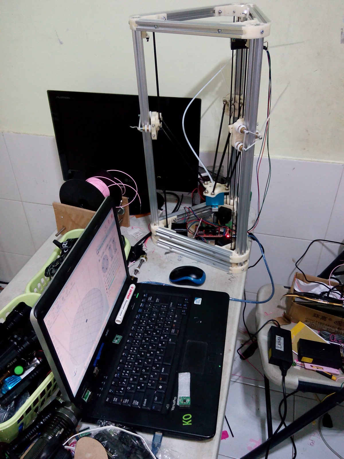
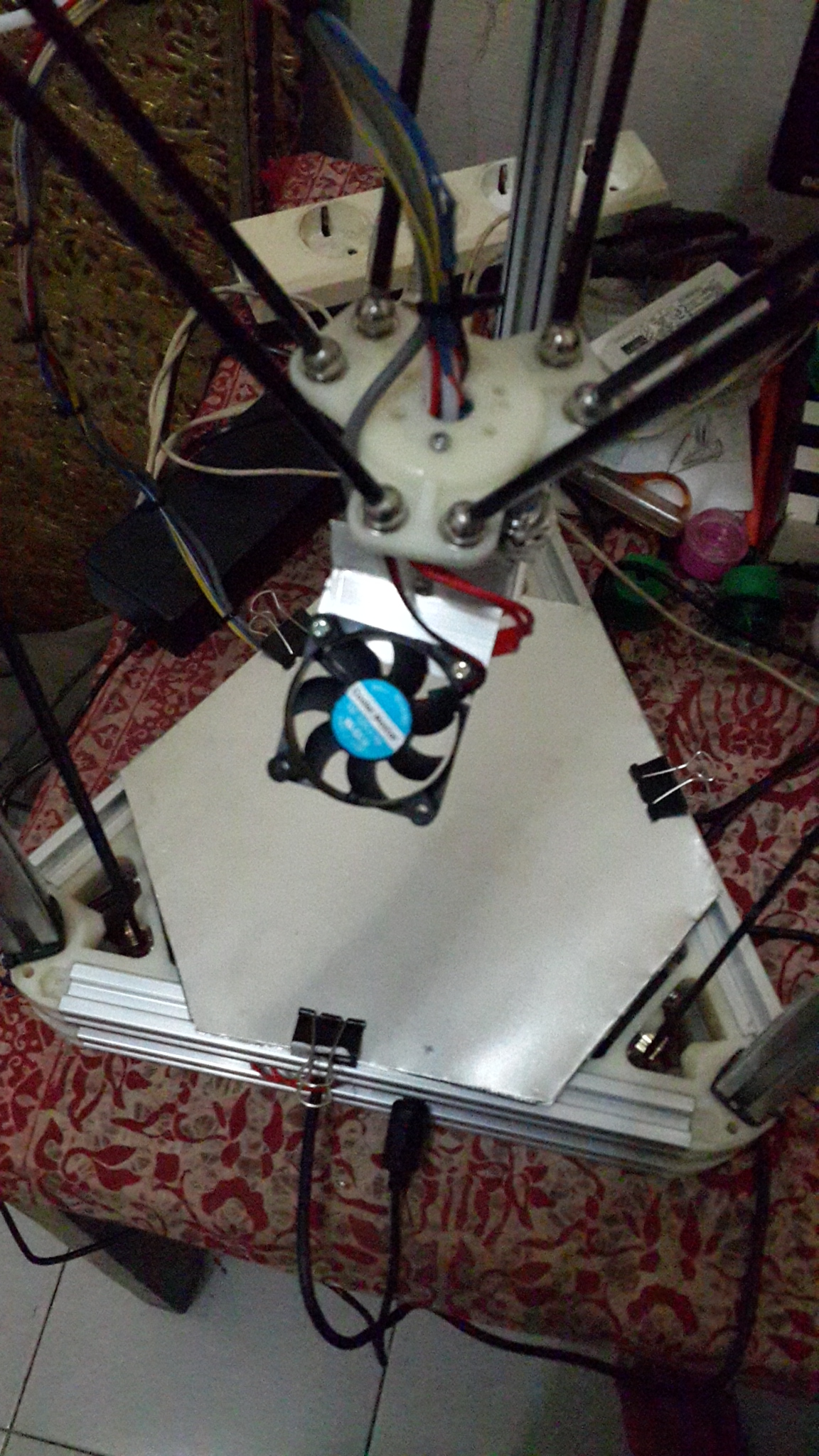
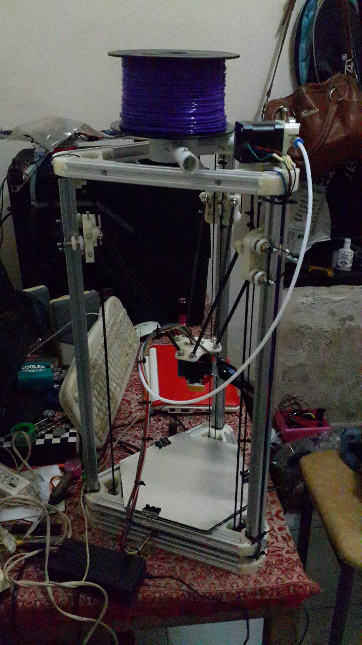
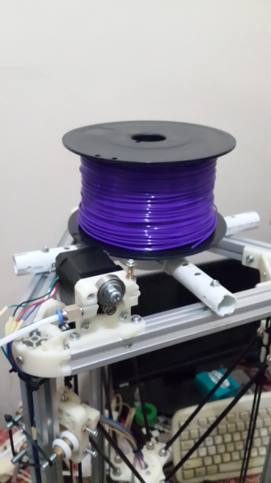
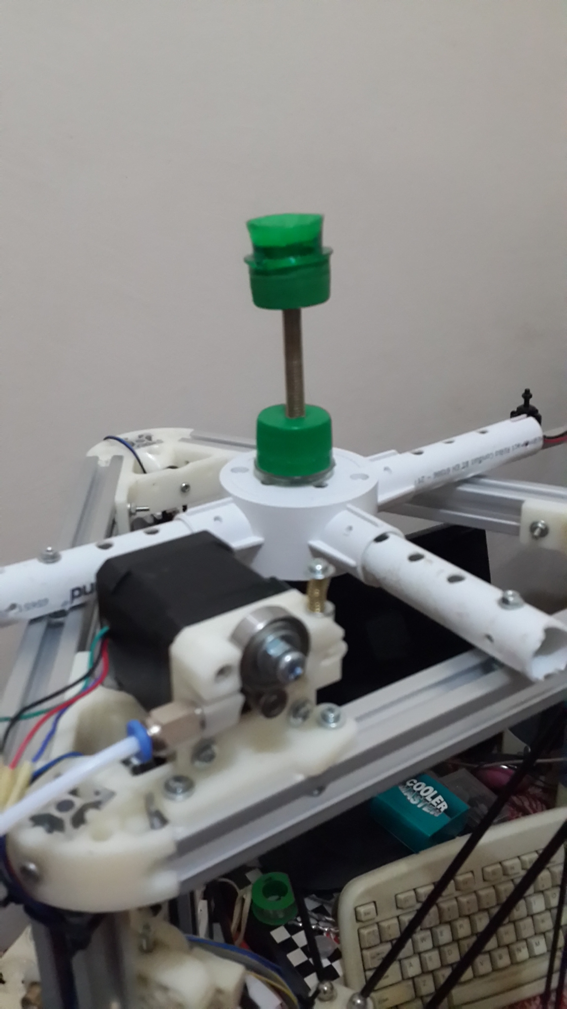
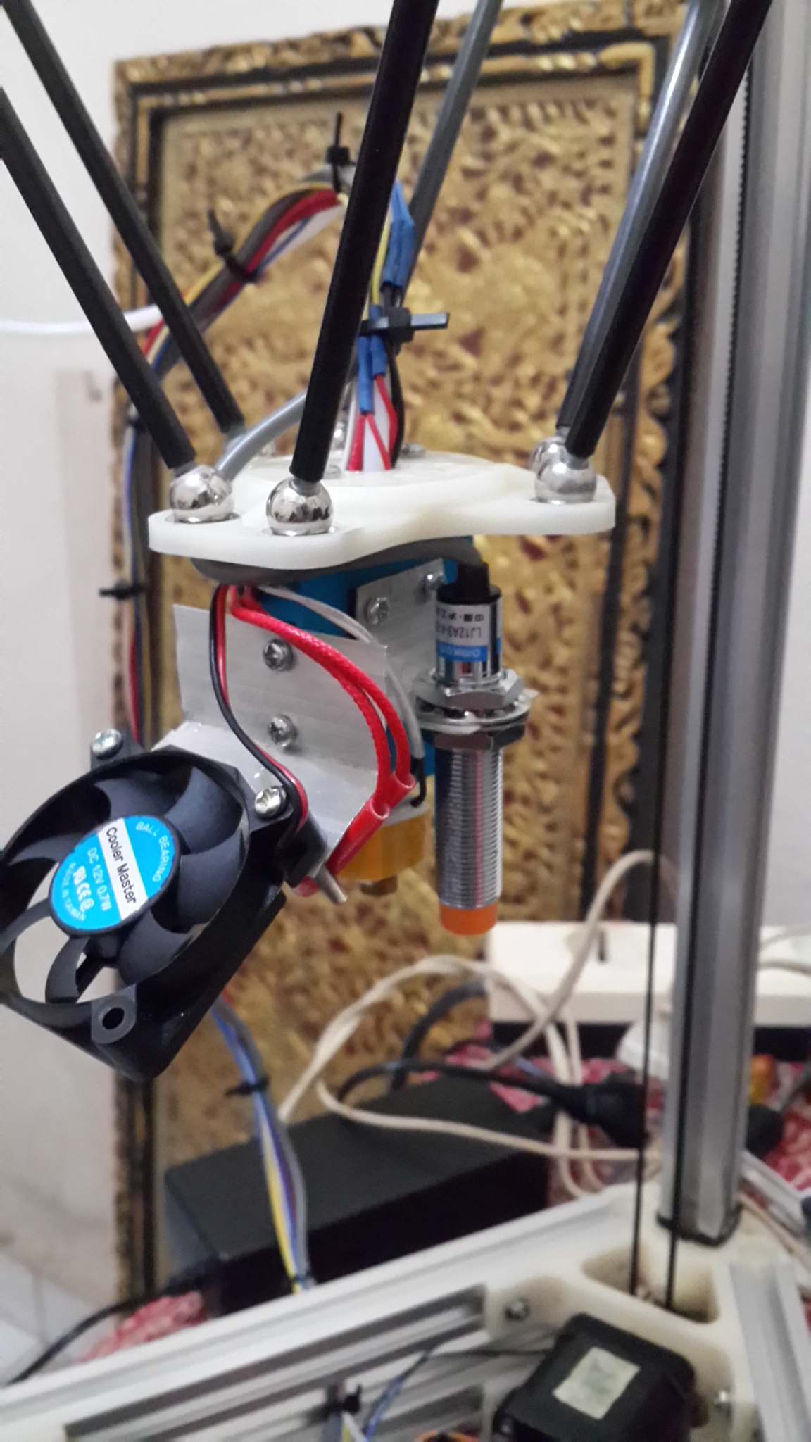
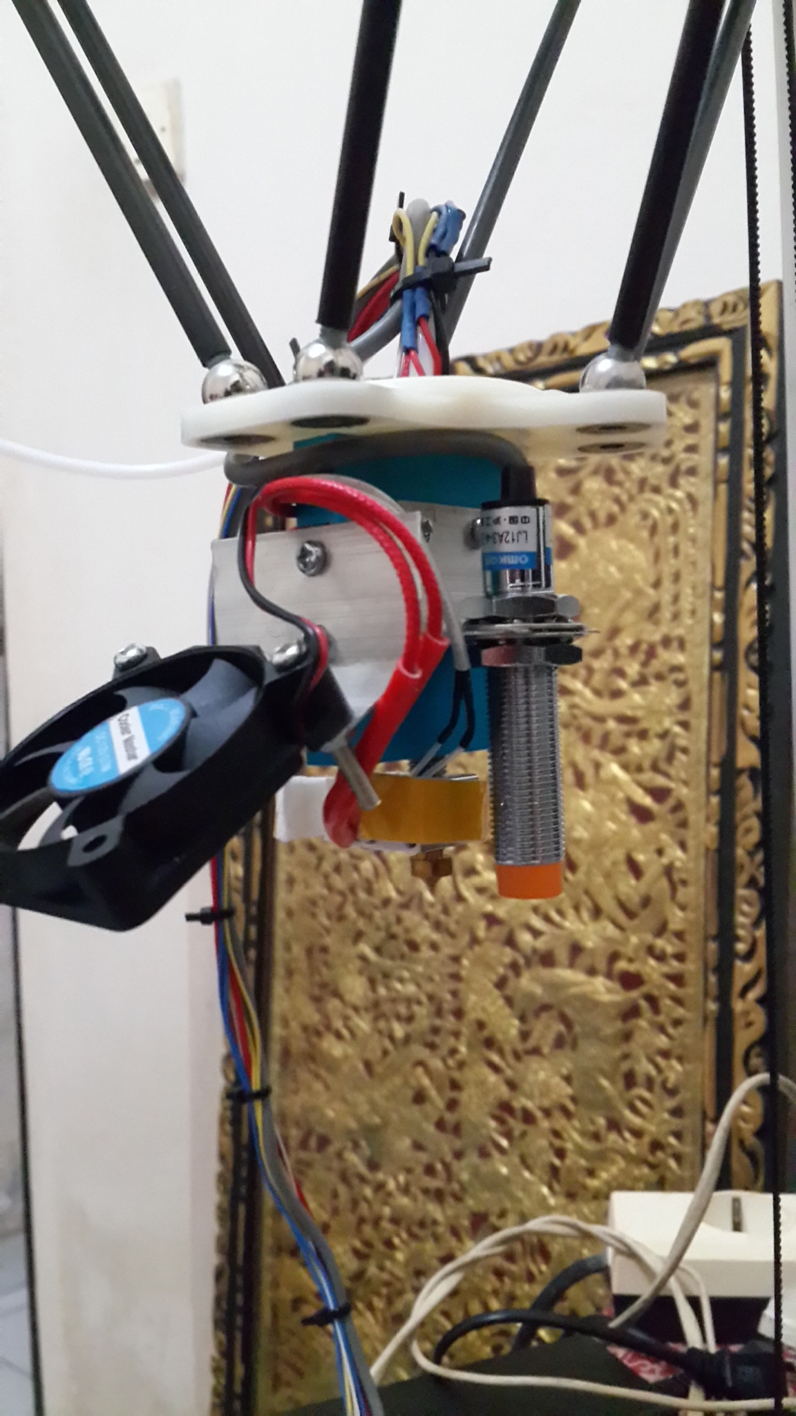
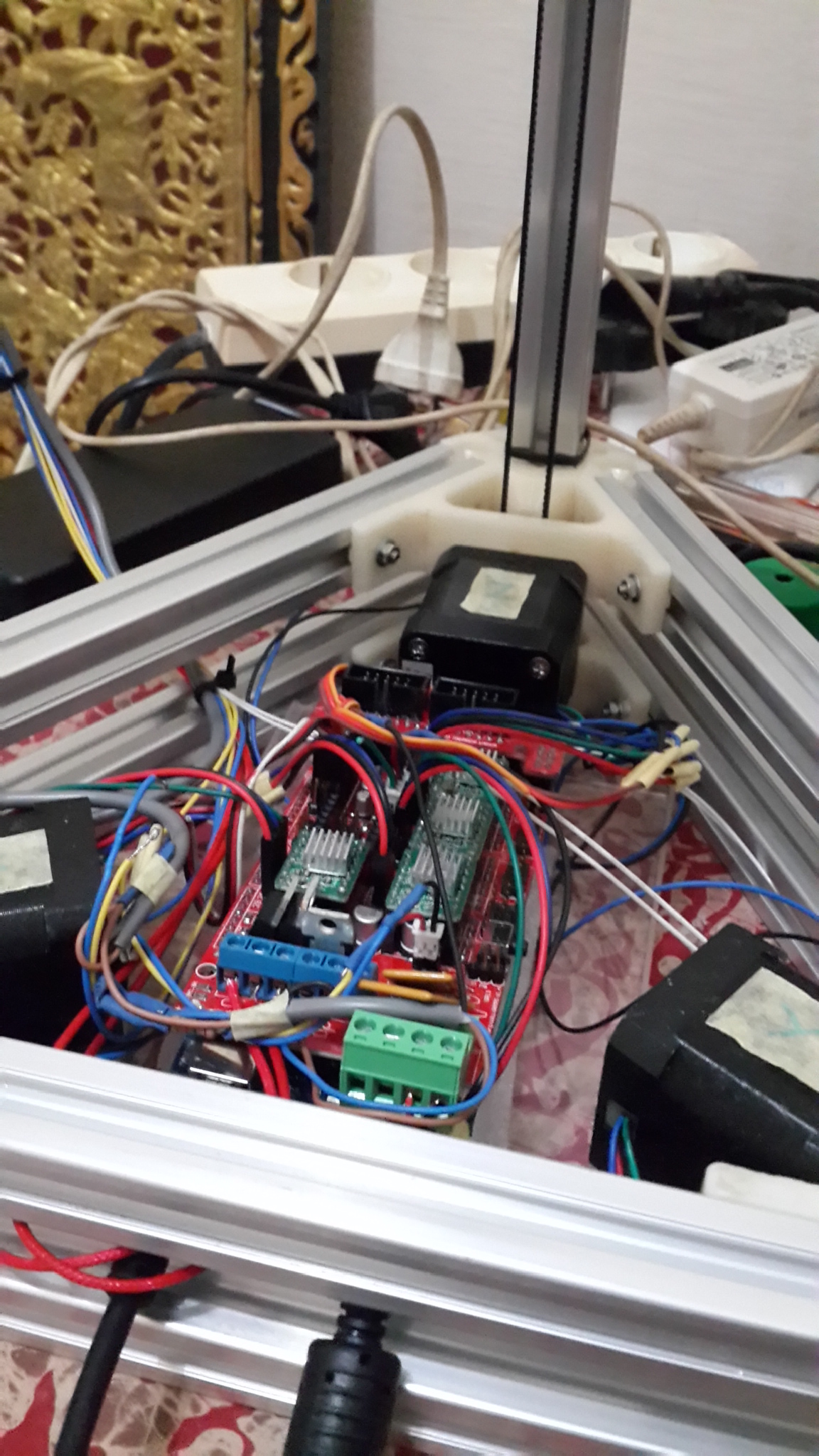
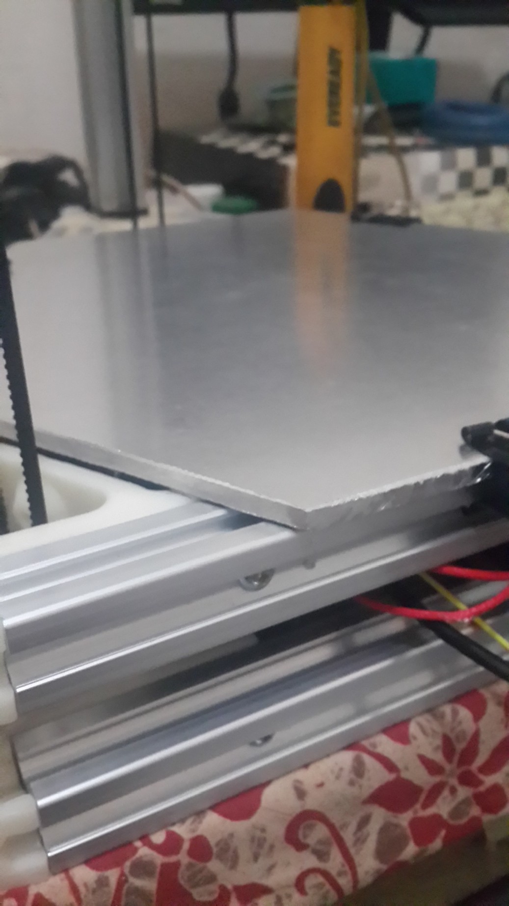
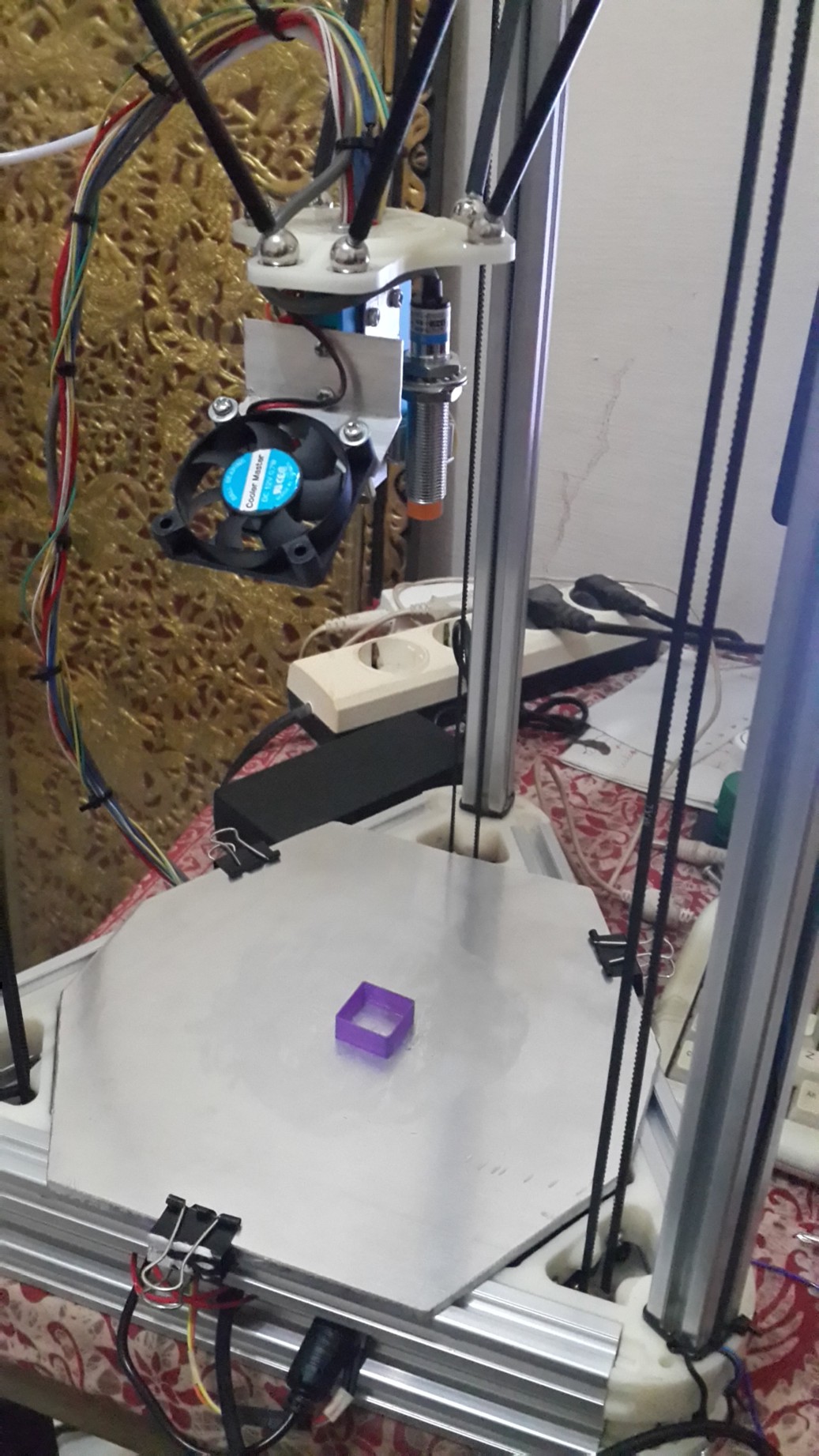
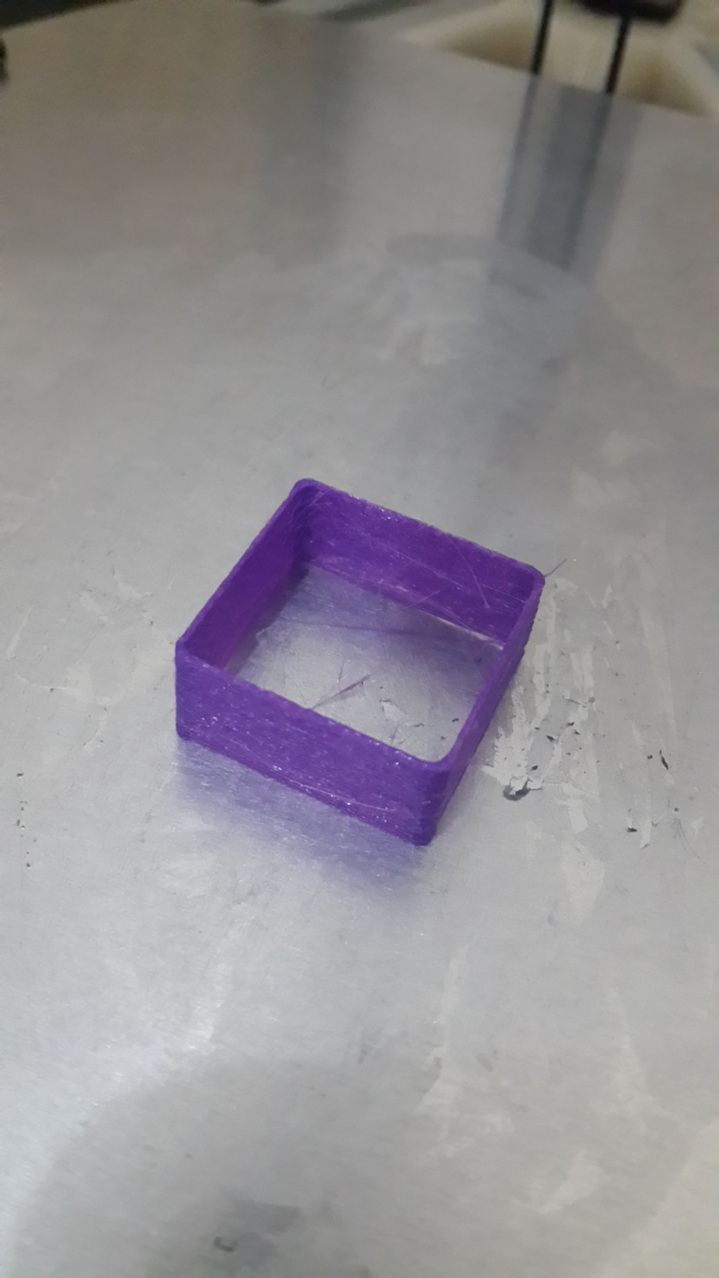
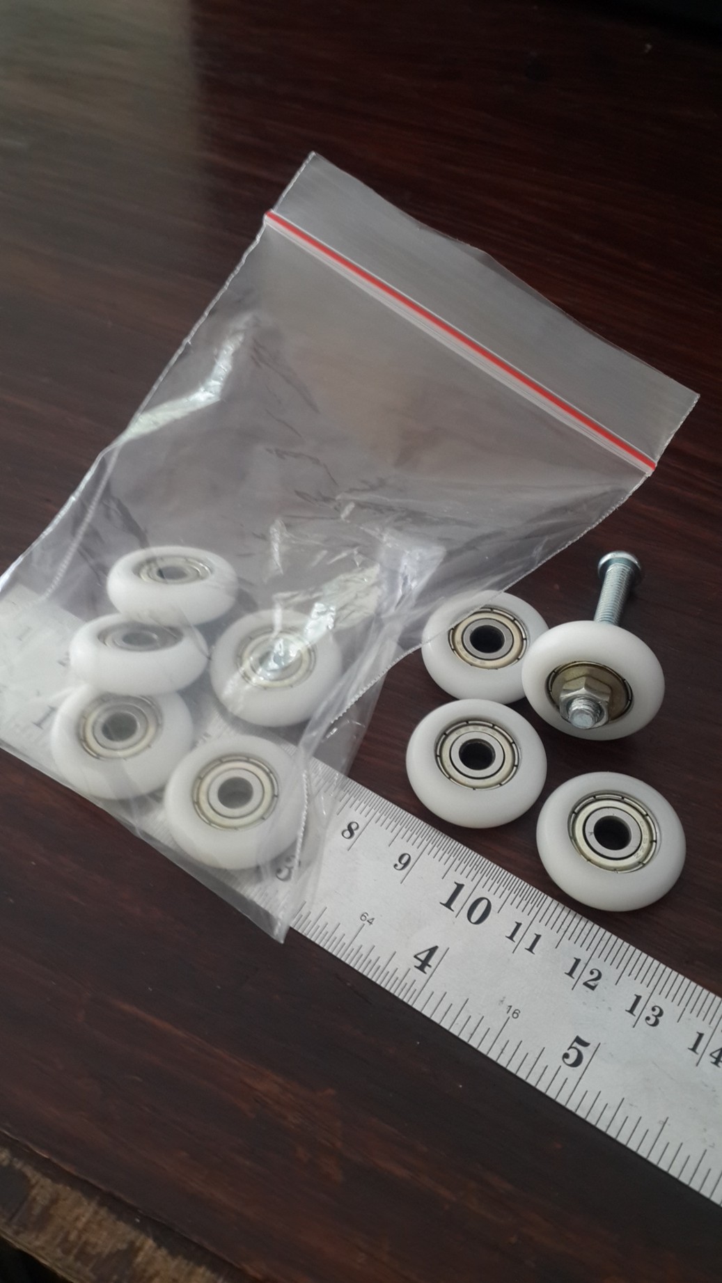
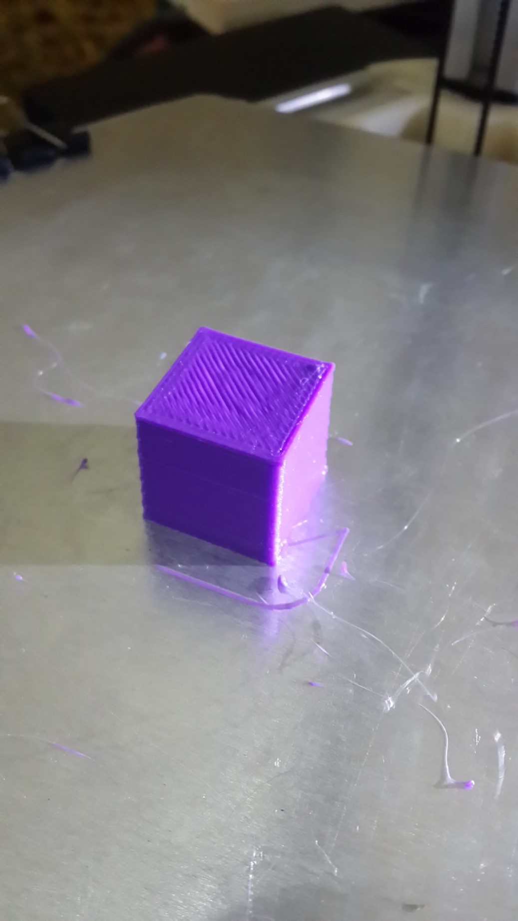
Sorry, only registered users may post in this forum.