Filament width sensor
Posted by zasf
|
Filament width sensor February 24, 2015 01:35PM |
Registered: 10 years ago Posts: 77 |
After building a filament extruder and starting making my own filament, I soon realized that it wasn't possible to measure it by hand with a caliper. Filament width is critical for printing therefore it is not possible to make filament without constantly checking its width.
For this reason I started looking around for solutions and I came out with my own version of a optical filament width sensor. The TSL1402R sensor is hooked on a Arduino Mega in order to show its output on a lcd screen.
This turned out to be a very good solution for constantly monitoring the extruded filament. If the shape of the line is shaggy, you know that the filament has bubbles in it or that it is not smooth. If it is too thick or too thin you can adjust temperature, extrusion speed, etc in order to meet the desired width.
I'm curios to know what you guys use or if you simply turn on the extruder and have constant width extruded filament
prusa i3
|
Re: Filament width sensor February 26, 2015 03:21PM |
Registered: 11 years ago Posts: 210 |
Good tolerances are no problem, at least with a Filastruder.
- [ABS: +/-0.02mm] (http://www.soliforum.com/topic/7430/abs-mg94-and-gp35-review-and-comparison/) in some cases users [report +/-0.01mm](http://www.soliforum.com/search/607487942/)
- [PLA: +/-0.03mm] (http://www.soliforum.com/topic/4108/my-filastruder-and-results-so-far-abs-and-pla/)
- [Nylon: +/-0.02mm] (http://www.soliforum.com/topic/8237/nylon-taulamn-618-regrind/)
- [Polycarbonate: +/-0.04mm] (http://www.soliforum.com/topic/9090/pc-polycarbonate-encom-pc-2012/)
- [PET - recycled T-glase: +/-0.05mm] (http://www.soliforum.com/topic/8876/pet-tglase-regrind/)
- [Acrylic: +/-0.05mm] (http://www.soliforum.com/topic/8499/acrylic/)
- [Polypropylene: +/-0.07mm] (http://www.soliforum.com/topic/8327/pp-polypropylene/)
Edited 1 time(s). Last edit at 02/26/2015 03:21PM by greenman100.
|
Re: Filament width sensor March 02, 2015 11:25AM |
Registered: 10 years ago Posts: 77 |
|
Re: Filament width sensor March 04, 2015 01:36AM |
Registered: 11 years ago Posts: 210 |
|
Re: Filament width sensor April 06, 2015 08:55AM |
Registered: 10 years ago Posts: 23 |
|
Re: Filament width sensor April 06, 2015 01:37PM |
Registered: 10 years ago Posts: 77 |
[www.thingiverse.com]
here you can find schematic and Arduino code for a simpler version based on Attiny85
here you can find schematic and Arduino code for a simpler version based on Attiny85
|
Re: Filament width sensor April 07, 2015 10:07AM |
Registered: 10 years ago Posts: 23 |
Thanks for that Zasf. I like this sensor because of your choice of the AT tiny a micro that can be programmed with arduino hardware compared to Filip Mulier's microcontroller. I've had a look at your arduino code. My programming skills are not wonderful so please bear with me. I have some questions.
1) Could you elaborate a little on the proceedure for calibration of your sensor as set out in the code. You have a line :
if (reading > 600) button_now_pressed = true; What's the significance of 600???
Is there a requirement for a calibration rod as with Filip Mulier's sensor.
2) Your code also mentions serial debug. How does this work with the Tiny? From your fritzing schematic I don't see any reference to a serial line.
Any help would be great.
|
Re: Filament width sensor April 07, 2015 01:02PM |
Registered: 10 years ago Posts: 77 |
Thanks for you interest. I also prefer Arduino like microcontrollersQuote
parto
Thanks for that Zasf. I like this sensor because of your choice of the AT tiny a micro that can be programmed with arduino hardware compared to Filip Mulier's microcontroller.

Quote
parto
1) Could you elaborate a little on the proceedure for calibration of your sensor as set out in the code. You have a line :
if (reading > 600) button_now_pressed = true; What's the significance of 600???
Pin 1 on the ATtiny85 is the one in charge of detecting button pressure. It is the only pin left and unfortunately it is the reset pin, but it can also be used as ADC although pulling it to ground will reset the microcontroller. Therefore it is connected to ground and 5V with two resistors, this is called 'voltage divider' and since the two resistors are equal, 2.5 volts will be provided (half of 5V), this means that AnalogRead will return 512 (1023 is 5 volts). When the button is pressed, the resistor connected to 5V is shorted out and therefore the voltage at pin 1 is greater than 2.5V which corresponds to 512. I used 600 just to stay on the safe side.
Quote
parto
Is there a requirement for a calibration rod as with Filip Mulier's sensor?
Filip uses a 2mm rod. I believe it is easier to use a filament that is known to be 1.75mm, that is why when pressing the button, the program will output 1.75 volts. Moreover different materials give different readings, so it is better to calibrate with the filament you're going to use. I assume that you have a piece of filament that it is exactly 1.75mm
Quote
parto
2) Your code also mentions serial debug. How does this work with the Tiny? From your fritzing schematic I don't see any reference to a serial line.
the code can be also compiled and uploaded to a Arduino Uno, in that case different pins are used and serial debug is available. You can also use a processing sketch to see the shape of the filament.
Quote
parto
Any help would be great.
In case you have further questions, just ask. If you want I can send you a pcb, as I have some spare.
|
Re: Filament width sensor April 09, 2015 07:46AM |
Registered: 10 years ago Posts: 23 |
I will try uploading the code to the Uno first in order to better understand what's going on in the sketch using the serial debug. It would be great if you could send me a pcb. Since I'm relatively new to reprap forum how do you set about securely exchanging contact details or email adresses???
|
Re: Filament width sensor April 09, 2015 02:39PM |
Registered: 10 years ago Posts: 77 |
Quote
parto
I will try uploading the code to the Uno first in order to better understand what's going on in the sketch using the serial debug. It would be great if you could send me a pcb. Since I'm relatively new to reprap forum how do you set about securely exchanging contact details or email adresses???
in order to see something you will need at least a Uno (or equivalent), pcb and TSL1401CL sensor. Then you will be able to see the shape of the shadow in processing like this [thingiverse-production-new.s3.amazonaws.com]
For the processing sketch, see [www.thingiverse.com]
As for the address, send me a private message (top right corner of the window).
|
Re: Filament width sensor May 02, 2015 05:53PM |
Registered: 10 years ago Posts: 23 |
With much help from Zasf I got his sensor up and running on my Gen 7 electronics. Big thanks Zasf!!! after which I decided to run some tests to verify some of my assumptions regarding the sensors operation under the new supporting version of Marlin.
I was a little confused about the automatic adjustments that the filament sensor makes to the flow rate of plastic compared to the M221 g code setting available under previous versions of Marlin, which is the firmware I use. My assumption was that (for the new version of marlin supporting the filament sensor) during a print, once you enable the filament sensor flow control using M405, that any adjustments to M221 were only momentarily enabled on the printer until the next filament flow rate was calculated from the latest measured filament diameter as measured by the sensor. This new flow rate then over wrote what M221 Sxx had dictated. I set up the following test to establish what was actually going on.
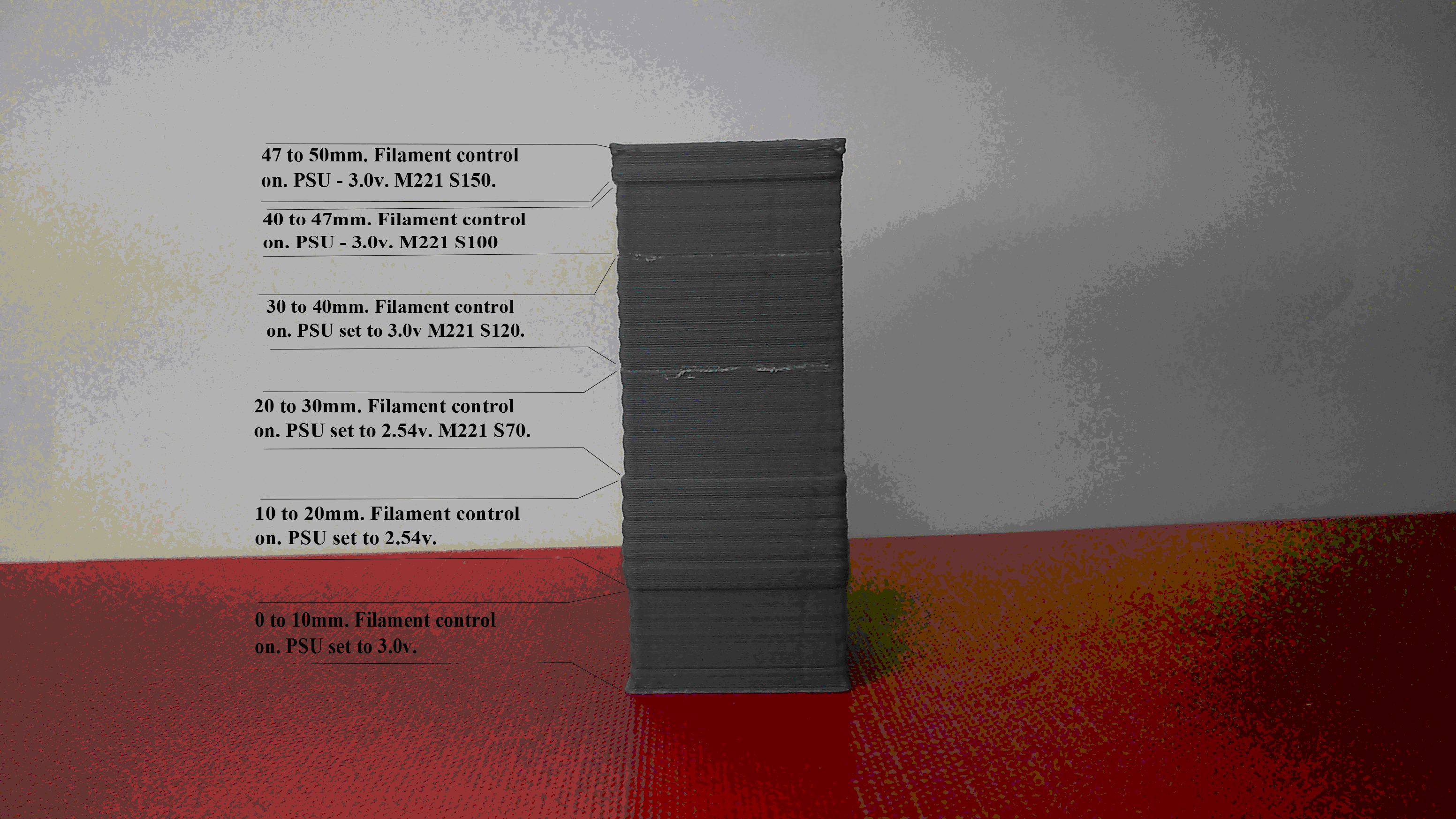
I don’t have the LCD setup on my printer to observe the volumetric_multiplier value that is calculated bases on the measured filament diameter. So in order to visually test the correct operation of the sensor, I printed a 50mm high by 20mm wide by 20mm long box. I used a commercially purchased good quality filament with consistent measured diameter of 2.97mm to print the whole piece. In order to simulate a changing filament diameter I connected the filament sensor input to my gen 7 pcb to a variable votage supply adjustable between 2.54 volts and 3 volts to simulate a filament diameter of 2.54 to 3mm. I printed the first 10 mm of the box with the sensor turned on using: M405 D0.5.
I set the D value very low because I want to observe straight away the effects of simulating changes in filament diameter. The psu voltage was set to 2.97 volts (simulating 2.97mm filament I’m using). See the pic of ABS box attached printing at 0.2mm, layer height(Excuse the ripple effect on my print. I have a Z axis wobble I need to fix.)
For the next section of the box; 10mm to 20 mm I turned the voltage down to 2.54v. The result of this is that the volumetric multiplier increases because the printer thinks the filament diameter has decreased while in fact it is a constant 2.97mm. The result is that this section of the box has thicker walls proving that the printer is auto compensating for what it thinks is a filament diameter decrease.
For the 20 to 30mm section of the box the psu is still at 2.54v and a M221 S70 command is issued. I did this to see if the printer would reduce the flow rate even though filament auto sensing and adjusting of diameter is still on. Since the resulting extrusion volume decreases, this suggests to me that the extrusion multiplier is a separate and independent parameter to the volumetric multiplier that the filament sensor routine uses. This gives us the facility to still adjust the filament flow if we feel that the auto filament sensing control of flow rate is still less than or more than it should be. Am I correct in this assumption?
In the section of the box 30 to 40 mm the psu was increased to 2.97vv and the M221 S120 command issued. In this section the wall thickness stayed much the same as in the 20-30mm. So in effect what seems to be happening here is that the volumetric multiplier is not compensating as it sees the filament diameter correctly at 3mm. while the extrusion multiplier controlled by M221 when set to S120 is overcompensating. The net effect is that the actual extrusion rate is more or less similar to what it was in the previous section of the box. For the final section 40-47mm the psu was left at 2.97v and M221 S100 was sent . The result was that the wall thickness didn’t seem to change very much. I was expecting that it would reduce slightly????? Maybe there is a very slight reduction. For the section 47-50mm the psu volatage is 3v and set M221 S120. As expected the wall thickness increases again.
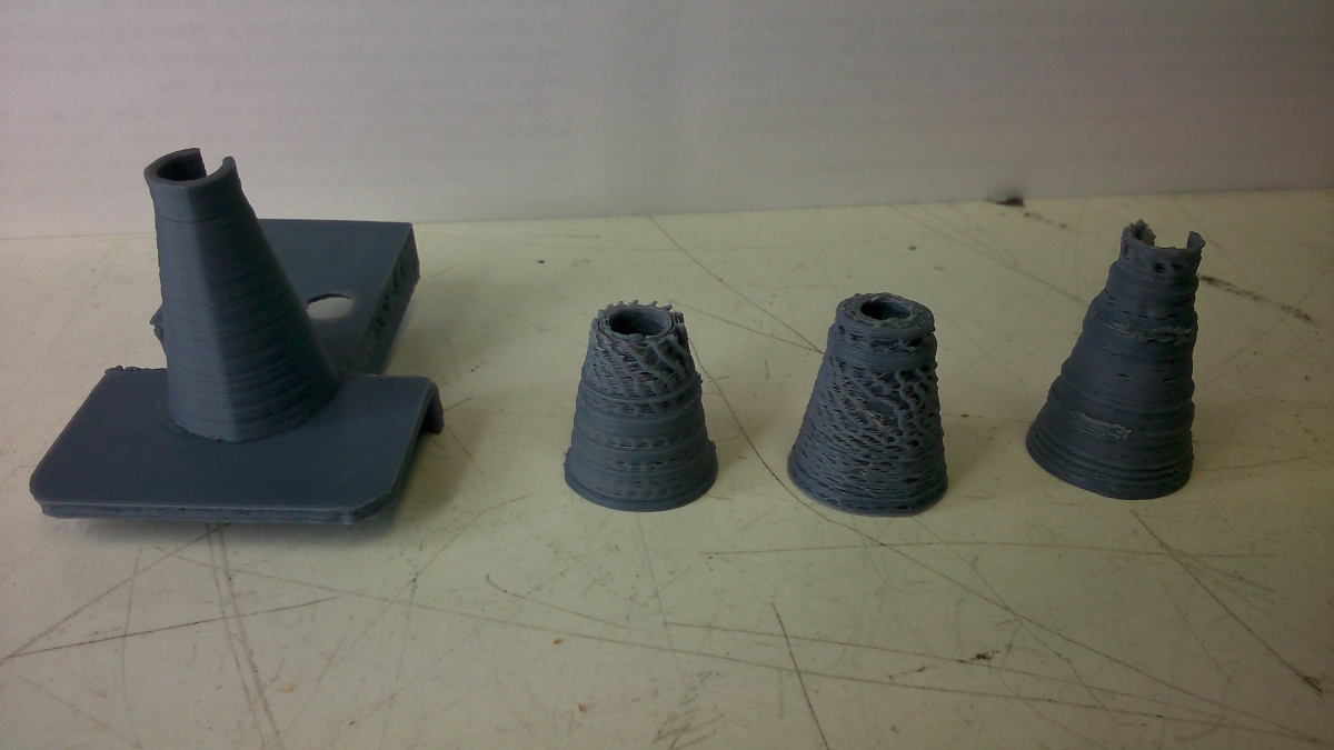
With some further testing I found something piuzzling. Small objects when printed on their own don’t seem to print properly using the sensor. In the second pic attached, the cone on the left was printed with the filament sensor turned off. (I printed the cone on its own. I've since glued it to the sensor top cover hence they appear together in the pic.) The other three cones were printed with M405 D13– filament sensor on. All other settings are the same. To eliminate the sensor as an issue, I printed the cone on the right using a psu to keep the input to the filament sensor on my Gen 7 pcb at a constant 2.9v (same diameter as my consistent diameter filament) yet I get these over extrusion rings that can be seen at different points on the print. I have no idea what is going on here. For bigger pieces as the 20mm x 20mm test box I don’t get this problem.
Since I’m using Gen 7 electronics which hasn’t previously been tested with the filament sensor there may be something about this set up that is causing the issues on small parts printed with the version of Marlin that supports the filament sensor. Has anyone seen this issue on a system using the Ramps board???
One final question about the new version of Marlin that supports the filament sensor. How is the filament extrusion rate calculated for the first 13 or so cms of filament between the sensor and the melt area of the print. Is the defailt filament diameter set in the slicer used ????
I was a little confused about the automatic adjustments that the filament sensor makes to the flow rate of plastic compared to the M221 g code setting available under previous versions of Marlin, which is the firmware I use. My assumption was that (for the new version of marlin supporting the filament sensor) during a print, once you enable the filament sensor flow control using M405, that any adjustments to M221 were only momentarily enabled on the printer until the next filament flow rate was calculated from the latest measured filament diameter as measured by the sensor. This new flow rate then over wrote what M221 Sxx had dictated. I set up the following test to establish what was actually going on.
I don’t have the LCD setup on my printer to observe the volumetric_multiplier value that is calculated bases on the measured filament diameter. So in order to visually test the correct operation of the sensor, I printed a 50mm high by 20mm wide by 20mm long box. I used a commercially purchased good quality filament with consistent measured diameter of 2.97mm to print the whole piece. In order to simulate a changing filament diameter I connected the filament sensor input to my gen 7 pcb to a variable votage supply adjustable between 2.54 volts and 3 volts to simulate a filament diameter of 2.54 to 3mm. I printed the first 10 mm of the box with the sensor turned on using: M405 D0.5.
I set the D value very low because I want to observe straight away the effects of simulating changes in filament diameter. The psu voltage was set to 2.97 volts (simulating 2.97mm filament I’m using). See the pic of ABS box attached printing at 0.2mm, layer height(Excuse the ripple effect on my print. I have a Z axis wobble I need to fix.)
For the next section of the box; 10mm to 20 mm I turned the voltage down to 2.54v. The result of this is that the volumetric multiplier increases because the printer thinks the filament diameter has decreased while in fact it is a constant 2.97mm. The result is that this section of the box has thicker walls proving that the printer is auto compensating for what it thinks is a filament diameter decrease.
For the 20 to 30mm section of the box the psu is still at 2.54v and a M221 S70 command is issued. I did this to see if the printer would reduce the flow rate even though filament auto sensing and adjusting of diameter is still on. Since the resulting extrusion volume decreases, this suggests to me that the extrusion multiplier is a separate and independent parameter to the volumetric multiplier that the filament sensor routine uses. This gives us the facility to still adjust the filament flow if we feel that the auto filament sensing control of flow rate is still less than or more than it should be. Am I correct in this assumption?
In the section of the box 30 to 40 mm the psu was increased to 2.97vv and the M221 S120 command issued. In this section the wall thickness stayed much the same as in the 20-30mm. So in effect what seems to be happening here is that the volumetric multiplier is not compensating as it sees the filament diameter correctly at 3mm. while the extrusion multiplier controlled by M221 when set to S120 is overcompensating. The net effect is that the actual extrusion rate is more or less similar to what it was in the previous section of the box. For the final section 40-47mm the psu was left at 2.97v and M221 S100 was sent . The result was that the wall thickness didn’t seem to change very much. I was expecting that it would reduce slightly????? Maybe there is a very slight reduction. For the section 47-50mm the psu volatage is 3v and set M221 S120. As expected the wall thickness increases again.
With some further testing I found something piuzzling. Small objects when printed on their own don’t seem to print properly using the sensor. In the second pic attached, the cone on the left was printed with the filament sensor turned off. (I printed the cone on its own. I've since glued it to the sensor top cover hence they appear together in the pic.) The other three cones were printed with M405 D13– filament sensor on. All other settings are the same. To eliminate the sensor as an issue, I printed the cone on the right using a psu to keep the input to the filament sensor on my Gen 7 pcb at a constant 2.9v (same diameter as my consistent diameter filament) yet I get these over extrusion rings that can be seen at different points on the print. I have no idea what is going on here. For bigger pieces as the 20mm x 20mm test box I don’t get this problem.
Since I’m using Gen 7 electronics which hasn’t previously been tested with the filament sensor there may be something about this set up that is causing the issues on small parts printed with the version of Marlin that supports the filament sensor. Has anyone seen this issue on a system using the Ramps board???
One final question about the new version of Marlin that supports the filament sensor. How is the filament extrusion rate calculated for the first 13 or so cms of filament between the sensor and the melt area of the print. Is the defailt filament diameter set in the slicer used ????
|
Re: Filament width sensor May 03, 2015 11:45PM |
Registered: 10 years ago Posts: 3 |
Here is some info on how Marlin uses the filament sensor readings:
M221 is a separate factor, (extrudemultiply) and independent of the factor controlled by the sensor (volumetric_multiplier[active_extruder]).
I am not sure why turning on the filament sensor control would cause the issues in your prints, especially if you are simulating it with a constant voltage at 3v. When you printed the cone the first time was it by itself or with other items on the bed?
Before 13 cm passes through the code uses the first reading in the buffer (first filament measurement).
|
Re: Filament width sensor May 04, 2015 10:24AM |
Registered: 10 years ago Posts: 23 |
Replying to Flipper; I will try some further tests in the coming days when I get a chance.
The first time I printed the cone it was with the top and botton half of the sensor housing also on the print bed and with M405 D13 at the start of my gcode. Once the printer was printing the cone only - having completed the top and botton housing - the under extrusion issues began to show. As I mentioned in my previous post, I did print the cone again on its own with the M406 gcode at the start of the print file and M405 D13 commented out but with all other setting the same and the results were fine as mentioned in my previous post.
If I start up a new print having had my printer powered off is this buffered data gathered during the previous print still available?? If so I assume it is saved to eeprom.???
Quote
When you printed the cone the first time was it by itself or with other items on the bed?
The first time I printed the cone it was with the top and botton half of the sensor housing also on the print bed and with M405 D13 at the start of my gcode. Once the printer was printing the cone only - having completed the top and botton housing - the under extrusion issues began to show. As I mentioned in my previous post, I did print the cone again on its own with the M406 gcode at the start of the print file and M405 D13 commented out but with all other setting the same and the results were fine as mentioned in my previous post.
Quote
Before 13 cm passes through the code uses the first reading in the buffer (first filament measurement).
If I start up a new print having had my printer powered off is this buffered data gathered during the previous print still available?? If so I assume it is saved to eeprom.???
|
Re: Filament width sensor May 04, 2015 03:06PM |
Registered: 10 years ago Posts: 77 |
Quote
flipper
M221 is a separate factor, (extrudemultiply) and independent of the factor controlled by the sensor (volumetric_multiplier[active_extruder]).
Thanks for this clarification, therefore in order to print the factor when issuing a M407 command the following should be added in Marlin_main.cpp
    case 407:   //M407 Display measured filament diameter
    {
    SERIAL_PROTOCOLPGM("Filament dia (measured mm): ");
    SERIAL_PROTOCOL(filament_width_meas);
    SERIAL_PROTOCOLPGM(", extrusion ratio(%): ");
    SERIAL_PROTOCOLLN(volumetric_multiplier[active_extruder]);
    }
    break
This could be useful for others like me not using lcds. Next step is to make Octoprint pick it up in the web interface.
Edited 1 time(s). Last edit at 05/05/2015 11:47AM by zasf.
|
Re: Filament width sensor May 07, 2015 12:55PM |
Registered: 10 years ago Posts: 77 |

|
Re: Filament width sensor September 03, 2015 11:38AM |
Registered: 10 years ago Posts: 23 |
Quote
flipper
Here is some info on how Marlin uses the filament sensor readings:
M221 is a separate factor, (extrudemultiply) and independent of the factor controlled by the sensor (volumetric_multiplier[active_extruder]).
I am not sure why turning on the filament sensor control would cause the issues in your prints, especially if you are simulating it with a constant voltage at 3v. When you printed the cone the first time was it by itself or with other items on the bed?
Before 13 cm passes through the code uses the first reading in the buffer (first filament measurement).
Filip,
I sorted the intermittent under extrusion issues I was having using my filament width sensor. I turned out to be the psu I was using to power the unit.
A question re. the filament width sensor and command M405. Is there a max value of D; the distance between the sensor and the extruder beyond which the firmware and sensor won't work properly. I ask because, I think if my filament sensor was attached to a non moving part of the printer rather than moving with the print head as it does currently, my measured diameter would be more stable. This however would mean that the "D" value would be multiple times my current setup which is about 13cms. Any thoughts???
Thanks,
Pat
|
Re: Filament width sensor October 02, 2015 09:13PM |
Registered: 10 years ago Posts: 3 |
The firmware can handle a D value of up to 20cm without changing the buffer size. You can increase the buffer size via #define MAX_MEASUREMENT_DELAY, but depending on how much ram you need and what board you are using, there will be a limit. I would think that you could increase to 100 cm and it would delay properly. One drawback of a long delay is that the printer is running 'blind' until the buffer is full. If the buffer is 100cm this means that the first 100cm of filament needs to move from the sensor to the extruder head before the system begins controlling the extruder dynamically. Until then, any changes in filament diameter will not cause a extruder speed change.
|
Re: Filament width sensor December 30, 2015 07:11AM |
Registered: 8 years ago Posts: 21 |
Hi,
How to program ATtiny85 microcontroller using arduino uno for this project , I mean any code to be written in IDE with modifications please guide me on this part
kindly send me the code which you have, i want to try this optical filament sensor and what are the changes to be made in marlin firmware help me in this part too?
Thanks in Advance
Sorry, only registered users may post in this forum.