Home
>
Library - projects, parts, arts, docs, and policy
>
Let's design something! (I've got an idea ...)
>
Topic
Wire Wound Stepper Motor
Posted by SnailRacer
|
Wire Wound Stepper Motor May 29, 2008 10:58PM |
Registered: 15 years ago Posts: 38 |
I'd like to make my own stepper motors...
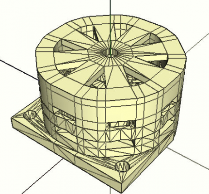
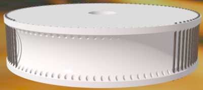
This design would let the rotor be wound with 17 gauge steel fencing wire so that it fits into slots around the rotor, and the same for the core of the magnets, which would then be wound with copper. The bearings would rest between a clip that would need to be attached to the rotor, and the cap, which would be attached to the outside magnet support. I didn't have a bearing here to measure, so the dimensions there are a guess. The nut would be a 14 mm (9/16") socket for a 3/8" rod.
If there are print quality issues with this it could be scaled up... the files are in cm scale.
** edit: old files removed
Edited 1 time(s). Last edit at 06/01/2008 06:25AM by Tim Attwood.
|
Re: Wire Wound Stepper Motor May 30, 2008 12:19AM |
Registered: 16 years ago Posts: 622 |
|
Re: Wire Wound Stepper Motor May 30, 2008 05:52AM |
Registered: 16 years ago Posts: 213 |
Wow, brilliant!
I'm just wondering, how do you wind the copper around the steel wire which is itself wound? If you made a pair of slots, one of each side of the steel windings, you could wind the copper separately, then slip it on the steel. Otherwise, it looks like you'd have to thread the windings by hand.
I suggest that you change the dimensions to millimeters, which is our recommended unit.
|
Re: Wire Wound Stepper Motor May 30, 2008 08:12AM |
Registered: 15 years ago Posts: 38 |
I was thinking to wind the steel wire in a figure eight on those, that should keep them pinched together more than the graphic shows, and leave some room for the copper. There needs to be room to attach the end caps to this as well, the caps will have the bearings to keep the rotor centered. It will be a bit of hand threading the wires, that seems a bit of a given, especially with the rotor.
mm scale seems a bit big for editors IMO, but it's easy enough to scale up.
[olytim.blogspot.com]
mm scale seems a bit big for editors IMO, but it's easy enough to scale up.
[olytim.blogspot.com]
|
Re: Wire Wound Stepper Motor May 30, 2008 10:53AM |
Registered: 16 years ago Posts: 370 |
|
Re: Wire Wound Stepper Motor May 30, 2008 03:45PM |
Admin Registered: 17 years ago Posts: 1,915 |
|
Re: Wire Wound Stepper Motor June 01, 2008 06:21AM |
Registered: 15 years ago Posts: 38 |
Enlarged everything up to mm scale, added some registration tabs to aid alignment, and a mounting bracket, widened the holes for winding the magnets a bit...
[olytim.blogspot.com]
|
Re: Wire Wound Stepper Motor June 02, 2008 03:10AM |
Registered: 16 years ago Posts: 622 |
|
Re: Wire Wound Stepper Motor June 02, 2008 03:18AM |
Admin Registered: 16 years ago Posts: 13,886 |
Hi Tim,
... instead of battling with friction, feeding-accuracy, gear-heads and such - why not build a linear-stepper as mentioned here: [forums.reprap.org] ?
This should be much simpler to realize in respect of winding coils and step-accuracy and would solve some problems with linearisation too.
Viktor
... instead of battling with friction, feeding-accuracy, gear-heads and such - why not build a linear-stepper as mentioned here: [forums.reprap.org] ?
This should be much simpler to realize in respect of winding coils and step-accuracy and would solve some problems with linearisation too.
Viktor
|
Re: Wire Wound Stepper Motor June 02, 2008 07:02AM |
Registered: 15 years ago Posts: 38 |
That would be elegantly simple, but the leverage of having the magnets move a rotor increases the torque. The bigger the wheel the more leverage.
How much weight the toothed stator design can lift would depend on the overall strength of the magnets, but the accuracy somewhat depends on keeping the magnet width small. Those are conflicting design requirements.
But the main problem is slippage, if the power is off then the toothed stator design is free to move. This rules out its use for lifting the Z axis, it'd drop the head into the table. You'd need a power-off brake to be safe.
|
Re: Wire Wound Stepper Motor June 04, 2008 02:31PM |
Registered: 16 years ago Posts: 293 |
I just love it when people don't just talk about things, but post an actual design! Nice rendering as well...
Oh, Tim, your thinking about the Z axis is valid, but the design of the Z axis is a little different than you think (I think). The weight on the platform could never cause a rotation of the stepper motor. There has been an old design that directly drove the table, but currently the Z platform is screwed up (well, not "screwed up") and down along threaded rods. It rests on 4 nuts at its corners (and 4 more anti-backlash nuts above that). The eight nuts on the Z-platform, and the bottom of the 3 idlers provide enough friction.
I'd love to see someone try building an actual motor! Actuators are definitely something we need if we want full replication. The torque requirements are not even that bad if you drive the steppers right (e.g. steady speed ramp ups to compensate for inertia of the (heavier) Y axis).
Exciting stuff!
Regards,
Erik de Bruijn
[Ultimaker.com] - [blog.erikdebruijn.nl]
|
Re: Wire Wound Stepper Motor June 08, 2008 02:15PM |
Registered: 16 years ago Posts: 161 |
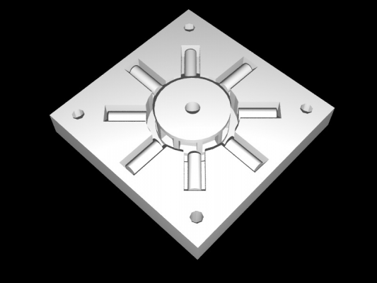
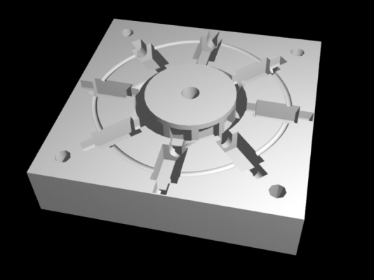
I made a stepper design too a little while ago but have only just got round to drawing it up on the computer.
Solid magnets are glued in place into the central rotor, then coils of wire are round round each of the metal bars in the outside section, then they are slotted into place. These could probably be made using fields metal, then have the reprap wind wire round it.
Solid magnets are glued in place into the central rotor, then coils of wire are round round each of the metal bars in the outside section, then they are slotted into place. These could probably be made using fields metal, then have the reprap wind wire round it.
|
Re: Wire Wound Stepper Motor June 10, 2008 06:40AM |
Registered: 15 years ago Posts: 38 |
While first pondering making stepper motors from readily available stuff, this rotor design struck me as fairly easy to assemble, just insert cut pieces of wire, or maybe magnets into the holes with glue.
Unfortunately this shape probably is beyond a typical Darwin. The small holes would need to match the wire size exactly, even if it was scaled up larger, so if you can't make the holes wire sized you'd need larger metal bits, maybe small bolts, or in GreenArrow's case magnets, but then you'd need room to space the bolts, which would make it somewhat larger, and then you face warping. Not to mention the overhanging parts...
The easiest solution would of course be to have a larger degree step, but then you would need a gearbox, and if you have a gearbox you'd need some way to deal with backlash, probably both software and feedback sensor changes, and if you do all that you might as well be using those cheap DC motors.
If you use permanent magnets in the rotor there will always be a little bit of attraction to the iron core in the electro-magnets, that would need to be overcome by extra electricity. On the plus side it would tend to keep the motor from slipping.
The only way to really know which design is best is to build them.
[olytim.blogspot.com]
|
Re: Wire Wound Stepper Motor June 10, 2008 06:56AM |
Registered: 16 years ago Posts: 293 |
About the resolution: RepRap might change to microstepping controllers anyway. I found a chip that is cheaper than the L297 / L298 chip combo and handles logic and driving power in a single-chip solution. If it indeed is a good option, this may become standard.
With microstepping the current is driven in a sinus shaped way (usually) and smaller steps and higher resultion and more smooth movement will become possible.
[en.wikipedia.org]
Regards,
Erik de Bruijn
[Ultimaker.com] - [blog.erikdebruijn.nl]
With microstepping the current is driven in a sinus shaped way (usually) and smaller steps and higher resultion and more smooth movement will become possible.
[en.wikipedia.org]
Regards,
Erik de Bruijn
[Ultimaker.com] - [blog.erikdebruijn.nl]
|
Re: Wire Wound Stepper Motor June 10, 2008 07:10AM |
Registered: 16 years ago Posts: 161 |
I don't think my design is very good for a practical use in a reprap (bulky, few steps per degree etc), but I designed it with the intention of simplicity just to see if I can get it working before refining the design.
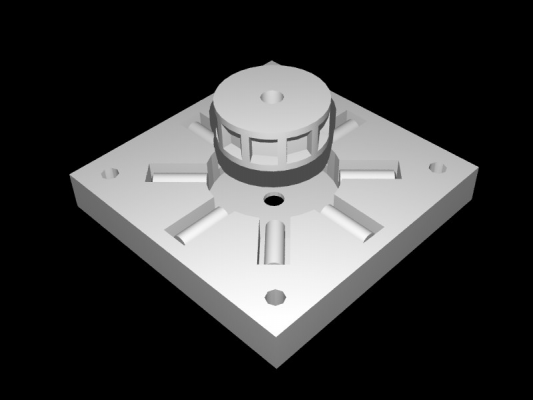
Here's a slight update with proper slots for the coils, and a channel for all the wiring to go through:
The rotor in the middle can't be reprapped without support material
Here's a slight update with proper slots for the coils, and a channel for all the wiring to go through:
The rotor in the middle can't be reprapped without support material
|
Re: Wire Wound Stepper Motor June 10, 2008 08:39AM |
Admin Registered: 17 years ago Posts: 7,879 |
>The rotor in the middle can't be reprapped without support material
If you make the top disc with concentric circles and you lay them down from the inside out I think it would probably work with ABS.
[www.hydraraptor.blogspot.com]
If you make the top disc with concentric circles and you lay them down from the inside out I think it would probably work with ABS.
[www.hydraraptor.blogspot.com]
|
Re: Wire Wound Stepper Motor June 10, 2008 09:39AM |
Admin Registered: 17 years ago Posts: 7,879 |
How many steps is this design?
Presumably if you get the numbers right you can get R * S where R is the rotor poles and S is the stator poles.
So in fact this looks like it has about 96 steps or are the coils in pairs?
[www.hydraraptor.blogspot.com]
Presumably if you get the numbers right you can get R * S where R is the rotor poles and S is the stator poles.
So in fact this looks like it has about 96 steps or are the coils in pairs?
[www.hydraraptor.blogspot.com]
|
Re: Wire Wound Stepper Motor June 10, 2008 10:15AM |
Registered: 16 years ago Posts: 161 |
There are 10 solid magnets on the rotor and 8 coils with the intention on running them in opposite pairs. (4 sets).
Do you know if there are any particular ratio of rotor poles to stator poles that work in stepper motors, or can it be pretty arbitrary? If I print them out on paper I could turn the rotor round to check the steps.
Edit: I just did that, now I think I understand stepper motors a lot better, and get why it is R * S, so I have answered my above questions
Micro stepping would give 80 steps which isn't bad.
The intended magnet is Q-08-08-04-N on [www.supermagnete.de]
These are
|
Re: Wire Wound Stepper Motor June 10, 2008 10:35AM |
Admin Registered: 17 years ago Posts: 7,879 |
No I don't know much about the design criteria for steppers but normally I think you have a lot more stator poles than coils by having toothed laminations. I think the number of rotor poles is less. In a tin can hydrid motor the rotor is a smooth cylinder but it must be magnetised with alternating poles around the circumference.
I have loads of motors, if you want I could open some up and post pictures and numbers.
[www.hydraraptor.blogspot.com]
I have loads of motors, if you want I could open some up and post pictures and numbers.
[www.hydraraptor.blogspot.com]
|
Re: Wire Wound Stepper Motor June 10, 2008 10:58AM |
Admin Registered: 17 years ago Posts: 7,879 |
Actually, thinking about it normal stepper motors don't work like this at all.
They don't have coils distributed radially, they are stacked along the length of the motor. Each coil energises a laminated pole piece which has the same number of poles as the rotor. The next section of the motor has another coil and and pole pieces but it is offset by the step angle. The advantage of this arrangment is that all the magnets are in use all the time.
Still this looks easier to fab, swaps some mechanical complexity for electronics.
[www.hydraraptor.blogspot.com]
|
Re: Wire Wound Stepper Motor November 21, 2008 02:00AM |
Registered: 16 years ago Posts: 213 |
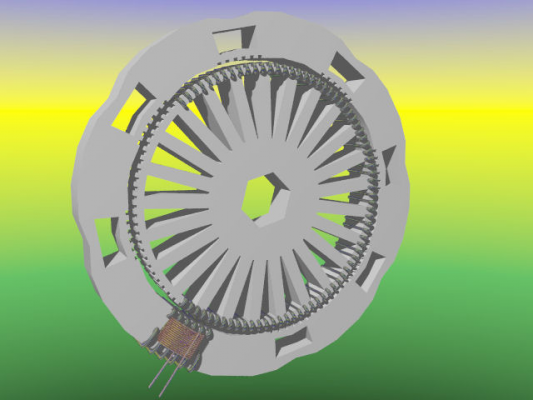
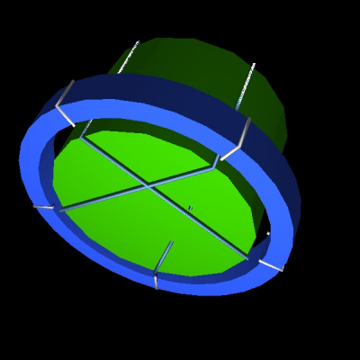
Below is a picture of a motor with lengthwise coils, as Nophead described. The rotor is a length of 17 gage wire, dark greyish blue in the picture, as Tim Attwood described, only it is wrapped around the disk, green in the picture; so it does not need to be threaded. For the pole pieces, staples are used, white in the picture. Staples have the U shape, which is excellent for containing and directing the flux toward the rotor. The coil is the ring around the rotor, blue in the picture. Only one stator ring is shown, the three others would be placed on top, offset by 1 / 20th of a revolution.
In the staple_stepper Art of Illusion model, the rotor is 40 mm high & 60 mm in diameter. The staples are 10 mm high & wide.
The prototype is a 5 rotor pole, 4 stator pole, for a total of 20 steps per revolution stepper. Eventually, with the precision of the reprap, it should be possible to make a hundred step per revolution motor, aka hectostepper.
When the coil is energized, magnetic flux flows concentrically around the coil, forming a toroid of flux. The U shaped staples around the stator coil, which are roughly in the same direction as the concentric flux, get magnetized and the magnetic flux emerges out of their tips. The flux attracts the poles of the rotor to the staples. Another way of looking at it is to visualize a U shaped electromagnet next to an iron rod. When the current is on the rod will be attracted to the electromagnet. In this motor, the U shape electromagnet and the rod are vertical, the rod is the wire around the sides of the rotor.
Below is an explanation derived from "Reluctance Motor" at wikipedia:
[en.wikipedia.org]
When a rotor pole is equidistant from the two adjacent stator poles, the rotor pole is said to be in the "fully unaligned position". This is the position of maximum magnetic reluctance for the rotor pole. In the "aligned position", the rotor poles are fully aligned with staple poles and is a position of minimum reluctance. When a stator pole is energized, the rotor torque is in the direction that will reduce reluctance. Thus the nearest rotor pole is pulled from the unaligned position into alignment with the stator field (a position of less reluctance). (This is the same effect used by a solenoid, or when picking up ferromagnetic metal with a magnet.) In order to sustain rotation, the stator field must rotate in advance of the rotor poles, thus constantly "pulling" the rotor along.
The four stacked stator rings have an offset of one quarter of the distance between the stator poles. To rotate the stator field, the offset stator poles are magnetized one after after another, then back to start. So stator ring one would be magnetized, then two, then three, then four, then back to one.
As can be seen, I am not a good graphic artist. I would like someone who is; to please work together with me to make a model that looks good and can be reprapped.
Edited 4 time(s). Last edit at 12/06/2008 02:45PM by Enrique.
|
Re: Wire Wound Stepper Motor October 23, 2011 04:45PM |
Sorry, only registered users may post in this forum.
