File list
This special page shows all uploaded files.
| Date | Name | Thumbnail | Size | User | Description | Versions |
|---|---|---|---|---|---|---|
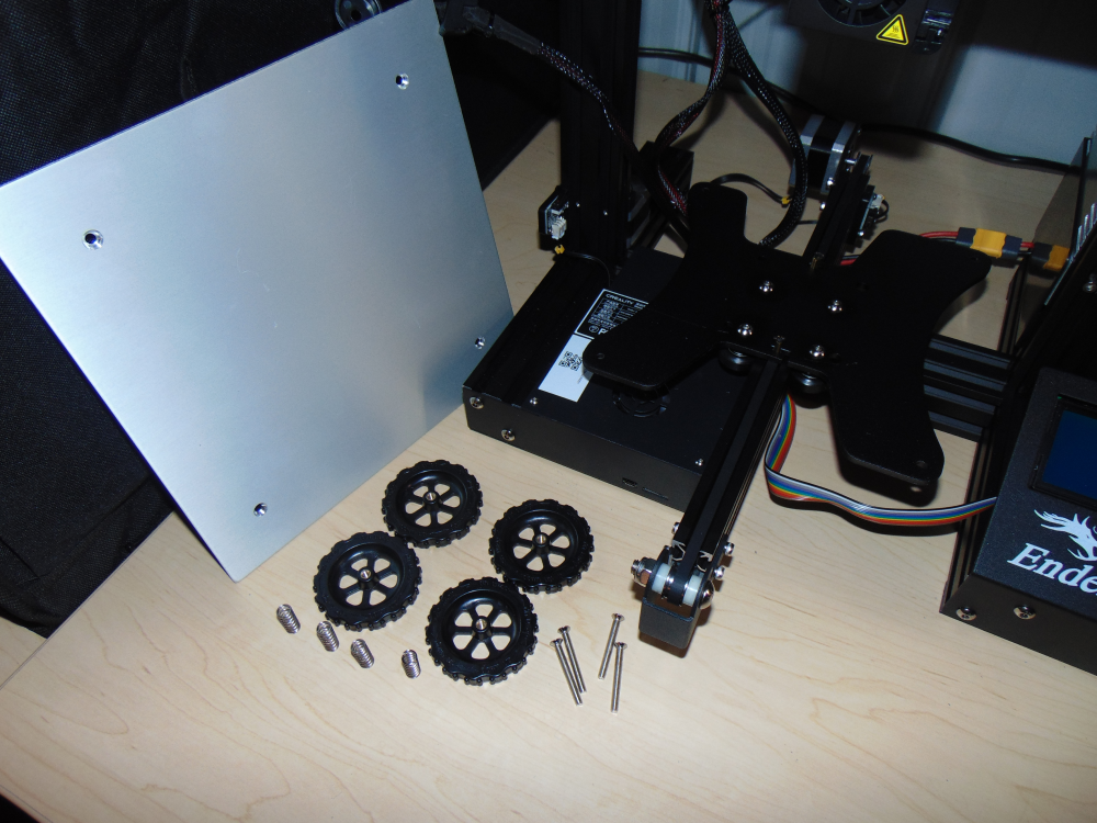
| 22:24, 14 February 2024 | DCS00264.png (file) |  |
973 KB | Engineeringfeind | 1 | |
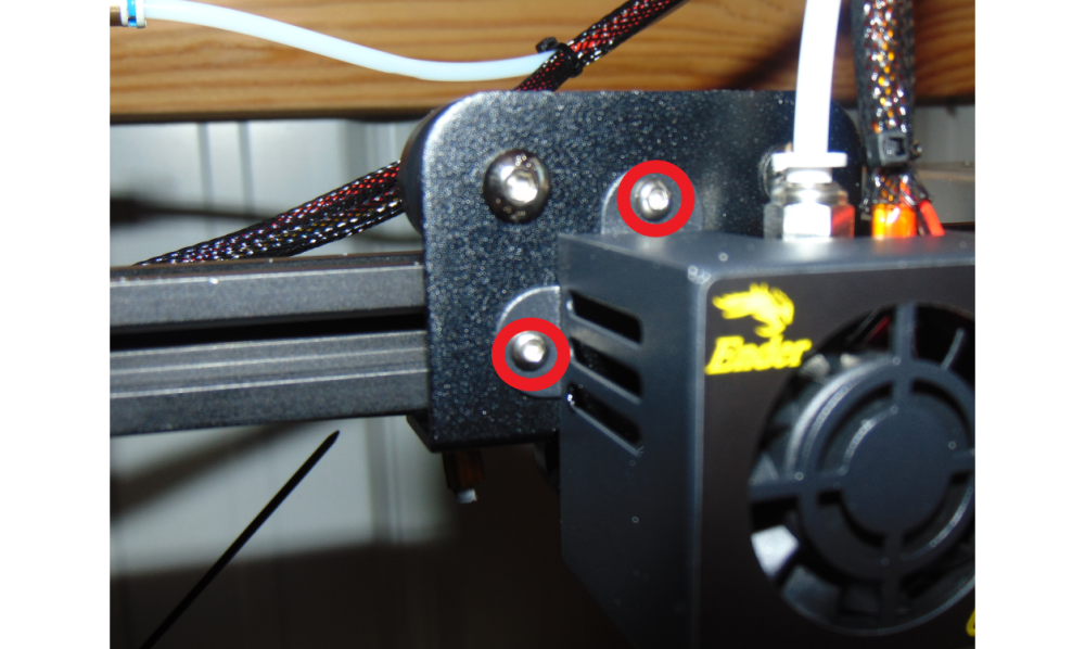
| 23:16, 14 February 2024 | Step two dissasembly.png (file) |  |
758 KB | Engineeringfeind | 1 | |
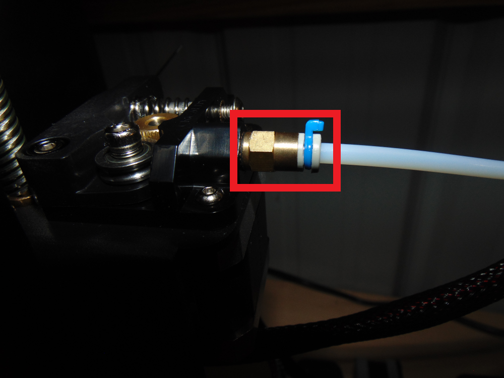
| 23:18, 14 February 2024 | Step two coupler dissasembly.png (file) |  |
577 KB | Engineeringfeind | 1 | |
| 01:39, 15 February 2024 | Klipper logo.png (file) | 20 KB | Hammersamatom | Logo of the Klipper firmware project | 1 | |
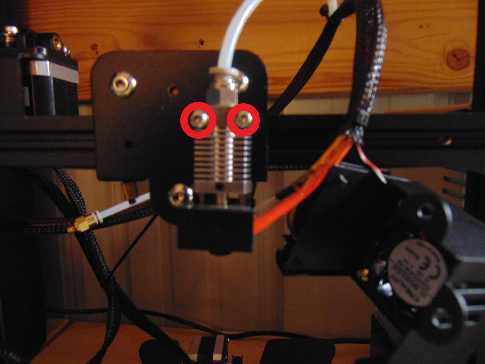
| 15:42, 15 February 2024 | Step 2 hotend dissasembly.png (file) |  |
989 KB | Engineeringfeind | 1 | |
| 16:35, 15 February 2024 | Pld sap front.png (file) |  |
99 KB | Seumag | PLD-SAP CAD front view | 1 |
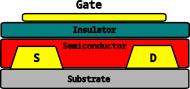
| 16:37, 15 February 2024 | BCTG.png (file) |  |
5 KB | Seumag | naive diagram of BCTG TFT | 1 |
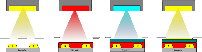
| 16:38, 15 February 2024 | BCTG process.png (file) | 23 KB | Seumag | Naive fabrication process by MM-PLD | 1 | |
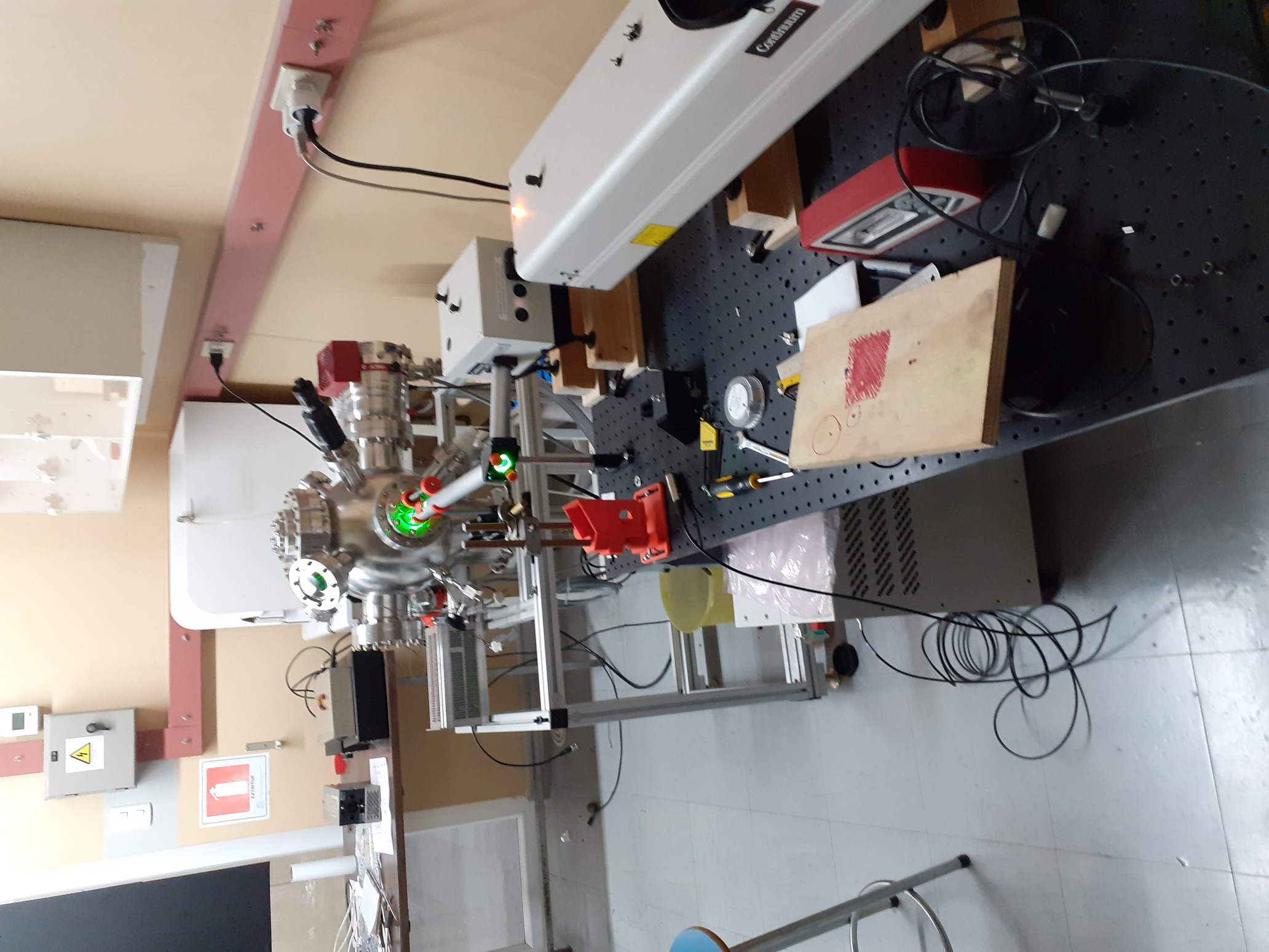
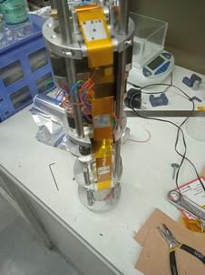
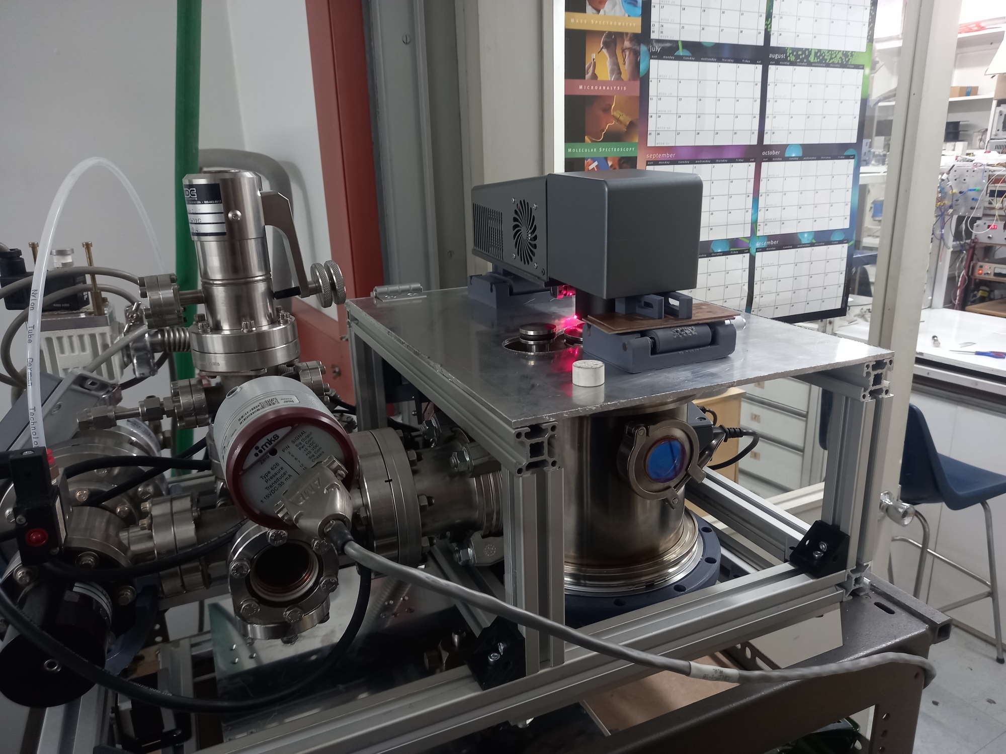
| 17:03, 15 February 2024 | Pld v0 setup.jpg (file) |  |
561 KB | Seumag | Standard configuration of the old PLD setup | 1 |
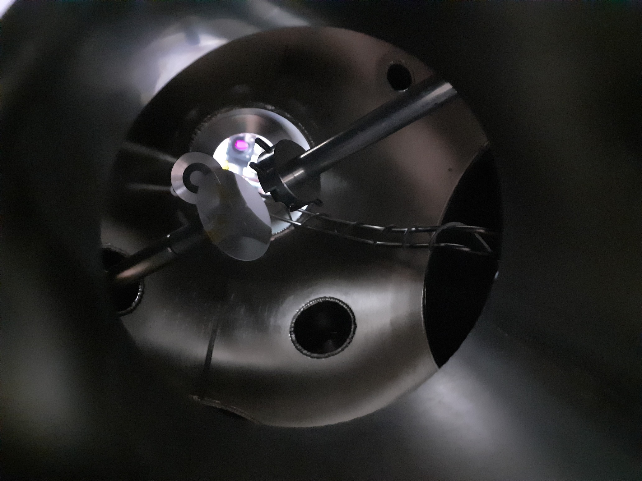
| 17:06, 15 February 2024 | PLD standard in.jpg (file) |  |
829 KB | Seumag | View into the chamber | 1 |
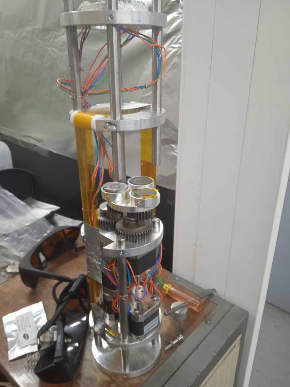
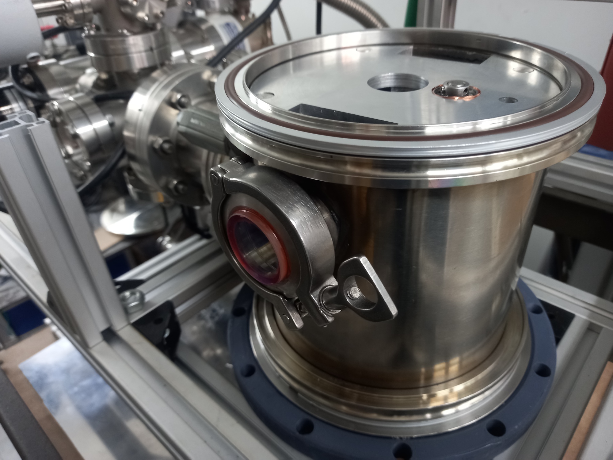
| 09:14, 16 February 2024 | PLD flange.jpg (file) |  |
327 KB | Seumag | overview of first implementation | 1 |
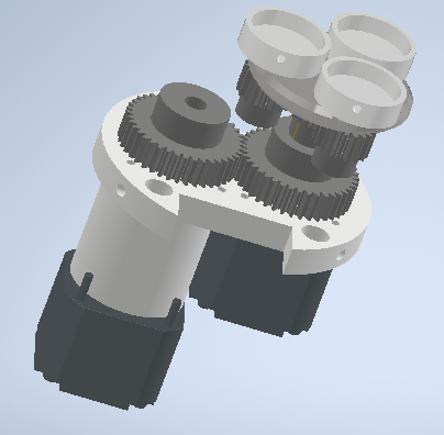
| 09:15, 16 February 2024 | Mec cinta.png (file) |  |
159 KB | Seumag | tape driving mechanism for the first implementation | 1 |
| 09:16, 16 February 2024 | Carrusel.png (file) |  |
103 KB | Seumag | Target carrousel design for the first implementation | 1 |
| 09:18, 16 February 2024 | Tape fab.png (file) |  |
144 KB | Seumag | mask's tape fabrication process | 1 |
| 09:18, 16 February 2024 | Mask cut.png (file) |  |
279 KB | Seumag | mask aperture cutting | 1 |
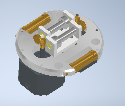
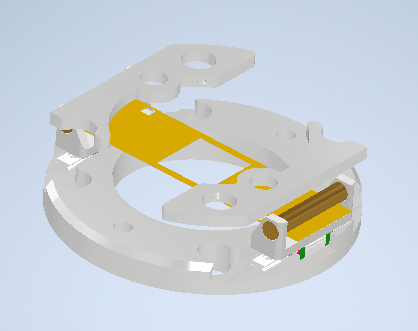
| 09:48, 16 February 2024 | Ajuste cinta.png (file) |  |
94 KB | Seumag | tape adjusting mechanism, cad | 1 |
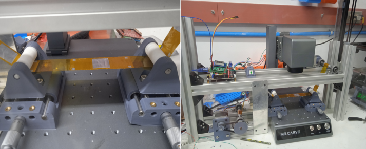
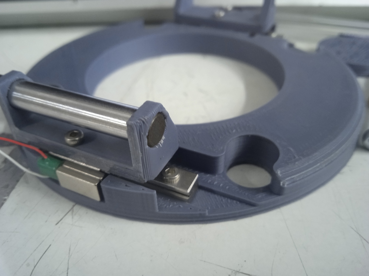
| 09:51, 16 February 2024 | Inertial slider.jpg (file) |  |
277 KB | Seumag | Prototype for the tape adjusting mechanism | 1 |
| 09:54, 16 February 2024 | Aligner Scheme.png (file) |  |
55 KB | Seumag | Diagram explaining the alignment mechanism | 1 |
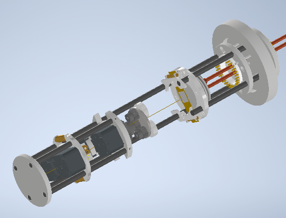
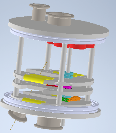
| 10:22, 16 February 2024 | PLD Cale.png (file) |  |
220 KB | Seumag | CAD Design, full | 1 |
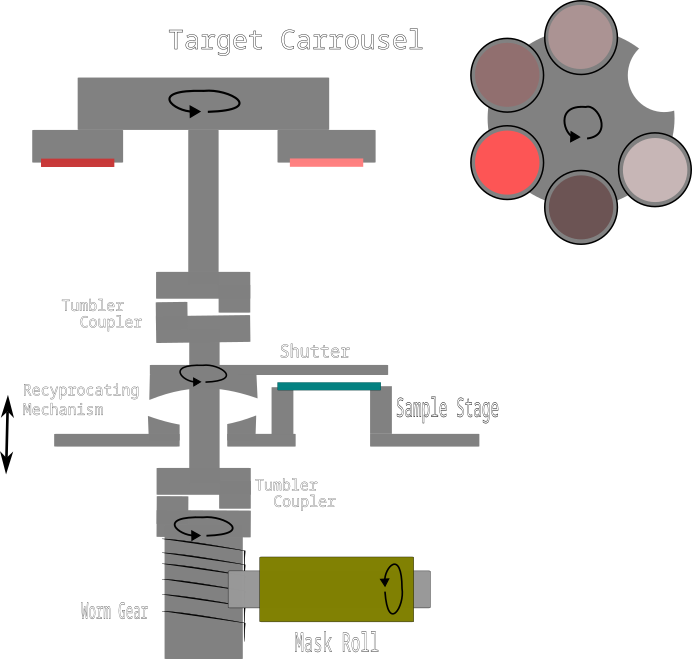
| 11:00, 16 February 2024 | Sap mechanism side.png (file) |  |
75 KB | Seumag | Diagram of main mechanism | 1 |
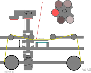
| 11:09, 16 February 2024 | Sap mechanism cut.png (file) |  |
24 KB | Seumag | PLD_SAP diagram, cutting masks | 1 |
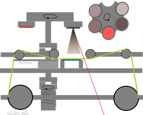
| 11:10, 16 February 2024 | Sap mechanism depo.png (file) |  |
24 KB | Seumag | PLD-SAP mechanism, during deposition | 1 |
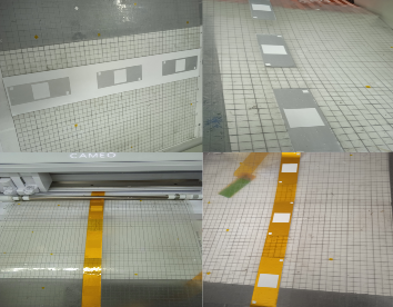
| 14:36, 17 February 2024 | Tape apertures.jpg (file) |  |
143 KB | Seumag | example of apertures cut onto the tape | 1 |
| 14:37, 17 February 2024 | Tape aperture det.jpg (file) |  |
600 KB | Seumag | Details of aperture cut onto tape | 1 |
| 14:38, 17 February 2024 | Tape aperture cut.jpg (file) |  |
525 KB | Seumag | apertures being cut | 1 |
| 14:39, 17 February 2024 | Tape mech.jpg (file) |  |
13 KB | Seumag | tape mechanism with apertures | 1 |
| 17:26, 20 February 2024 | Step 2 after.png (file) |  |
990 KB | Engineeringfeind | 2 | |
| 17:27, 20 February 2024 | Step 4a after.png (file) |  |
990 KB | Engineeringfeind | 1 | |
| 17:29, 20 February 2024 | Step 4b before.png (file) |  |
987 KB | Engineeringfeind | 1 | |
| 17:32, 20 February 2024 | Pld sap flanges.png (file) |  |
122 KB | Seumag | more up to date version of the design | 1 |
| 17:32, 20 February 2024 | Step 3 after image 2.png (file) |  |
888 KB | Engineeringfeind | 1 | |
| 17:44, 20 February 2024 | Step 3 after.png (file) |  |
845 KB | Engineeringfeind | 1 | |
| 17:44, 20 February 2024 | Step 3 before.png (file) |  |
983 KB | Engineeringfeind | 1 | |
| 17:45, 20 February 2024 | Stage one complete.png (file) |  |
960 KB | Engineeringfeind | 1 | |
| 02:22, 23 February 2024 | Voron.jpg (file) |  |
267 KB | Simon.pilepich | Voron 0.2 | 1 |
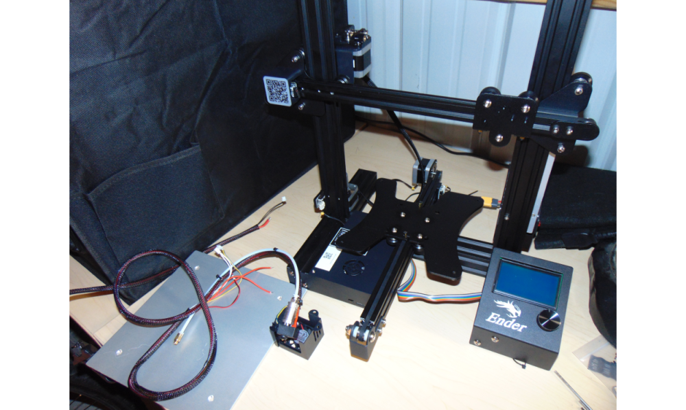
| 04:31, 23 February 2024 | Ratrig.jpg (file) |  |
227 KB | Simon.pilepich | 1 | |
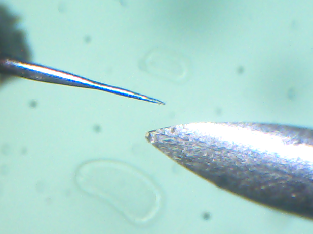
| 23:51, 6 March 2024 | Probe tip and hypodermic.png (file) |  |
293 KB | VikOlliver | Tip of a 24 gauge hypodermic needle (right) and an electrically etched probe top with a tip radius of approximately 0.25µm | 1 |
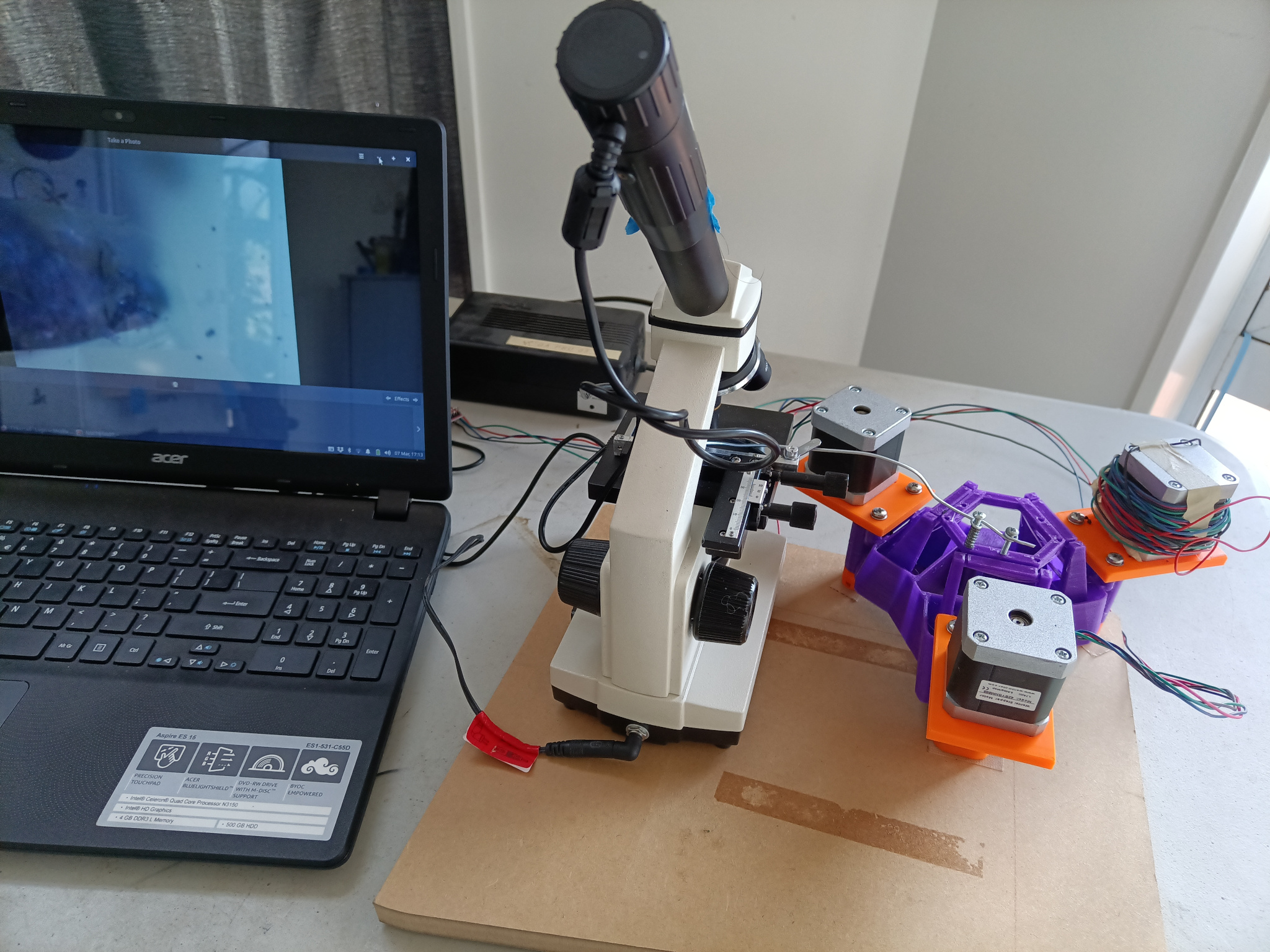
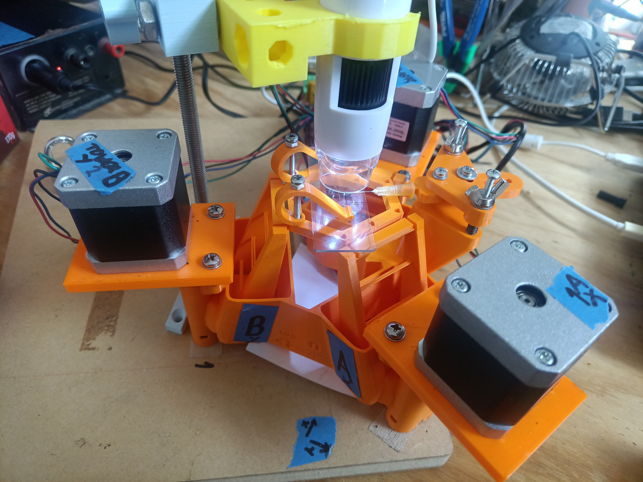
| 00:24, 7 March 2024 | URepRap first test rig.jpg (file) |  |
966 KB | VikOlliver | Initial test rig using OpenFlexure Delta stage with a single functional stepper and a wire probe being observed through a microscope. | 1 |
| 03:29, 11 March 2024 | URepRap logo.png (file) | 38 KB | VikOlliver | RepRap logo with a micron in the middle | 1 | |
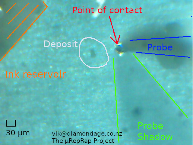
| 20:12, 12 March 2024 | 2024-03-13-084007 annotated.jpg (file) |  |
111 KB | VikOlliver | Annotated image showing deposition made with a 40μm hypodermic tip. | 1 |
| 00:20, 1 April 2024 | First square with M3 2024-04-01 14-07-00.jpg (file) |  |
143 KB | VikOlliver | Markings in Sharpie on a microscope slide etched with a 1.0mm square enclosing a 0.5mm square. Lower right shows fragment of M3 screw thread with 0.5mm pitch for scale. | 1 |
| 18:16, 4 April 2024 | Mk2 experimental 20240401 141636 386.jpg (file) |  |
771 KB | VikOlliver | Second experimental platform for μRepRap using indirect lighting stage, robust probe arm, and feet with endstop switches. | 1 |
| 19:29, 30 April 2024 | 400um logo 3rd attempt.jpg (file) | 44 KB | VikOlliver | RepRapMicron logo 400μm tall with scale bar. Scratched in Sharpie marker with a hypodermic needle on the "Titch" prototype. | 1 | |
| 19:37, 30 April 2024 | Titch 20240429 183325 345.jpg (file) |  |
533 KB | VikOlliver | The "Titch" prototype based on an OpenFlexure Block Stage | 1 |
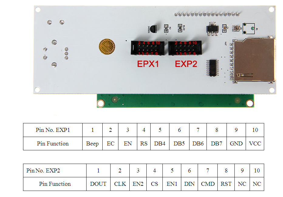
| 09:27, 8 May 2024 | LCD 2004 PINOUT.png (file) |  |
332 KB | Simon.pilepich | Pinout of LCD2004 | 1 |
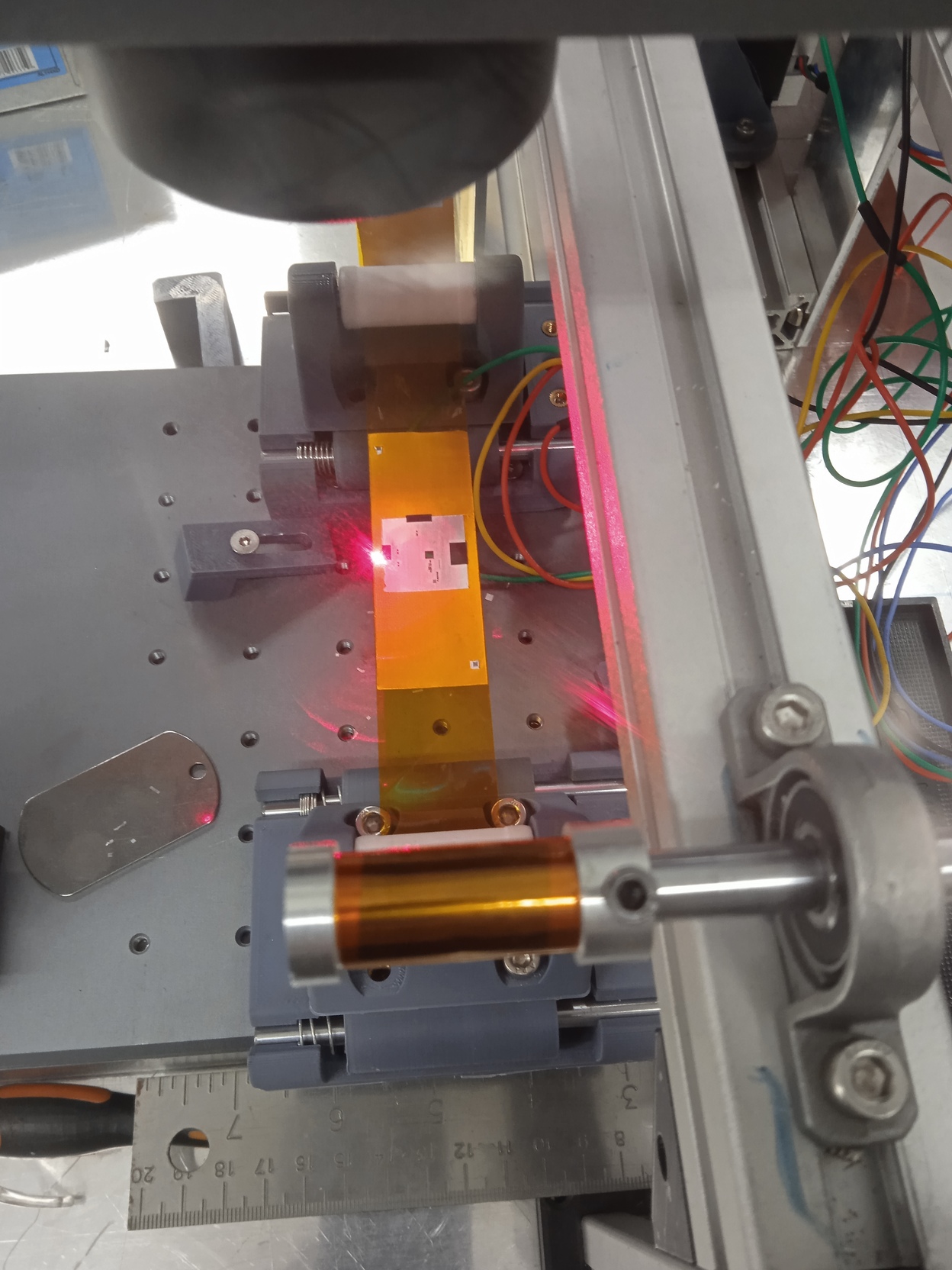
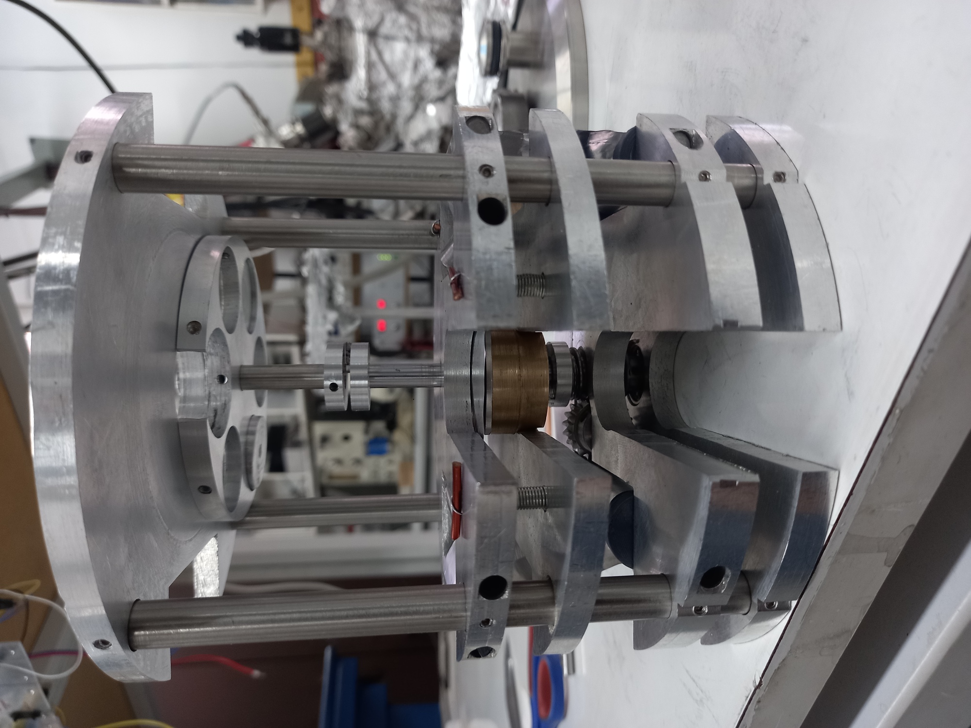
| 13:46, 21 May 2024 | Sap mech in chamber.jpg (file) |  |
718 KB | Seumag | Fit of the mechanism in the chamber | 1 |
| 13:48, 21 May 2024 | Sap mask machining.jpg (file) |  |
861 KB | Seumag | mask machining experiment | 1 |
| 13:49, 21 May 2024 | Sap targets.jpg (file) |  |
661 KB | Seumag | Multitarget view | 1 |
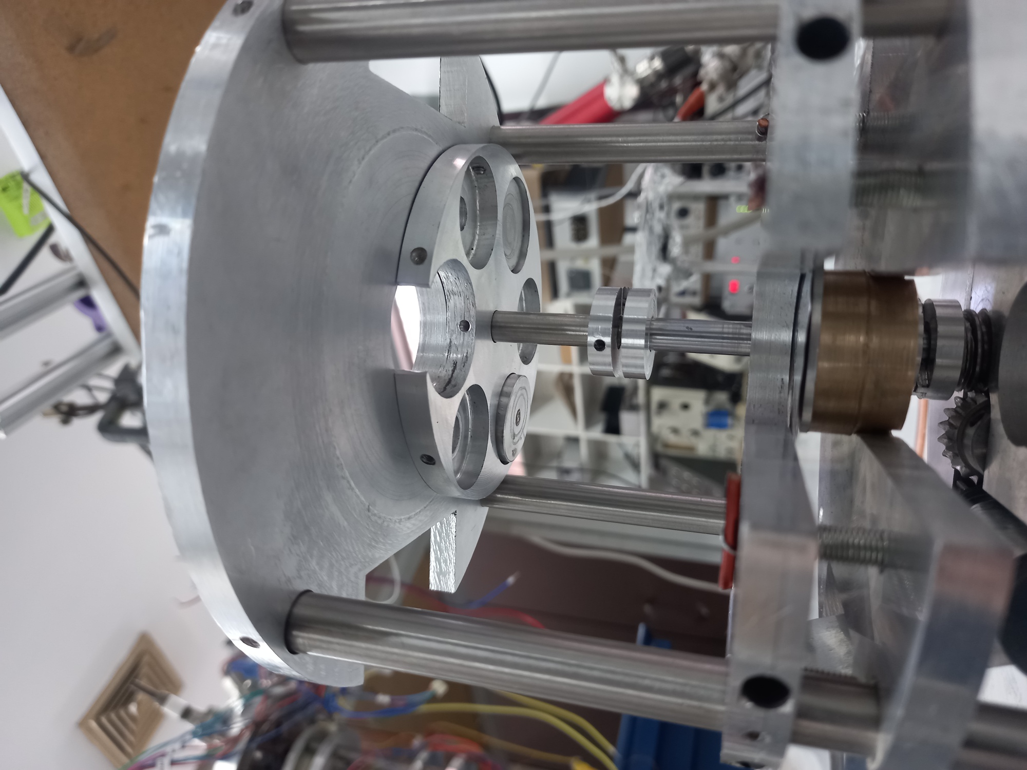
| 13:54, 21 May 2024 | Sap front view mech.jpg (file) |  |
814 KB | Seumag | mechanism front view | 1 |
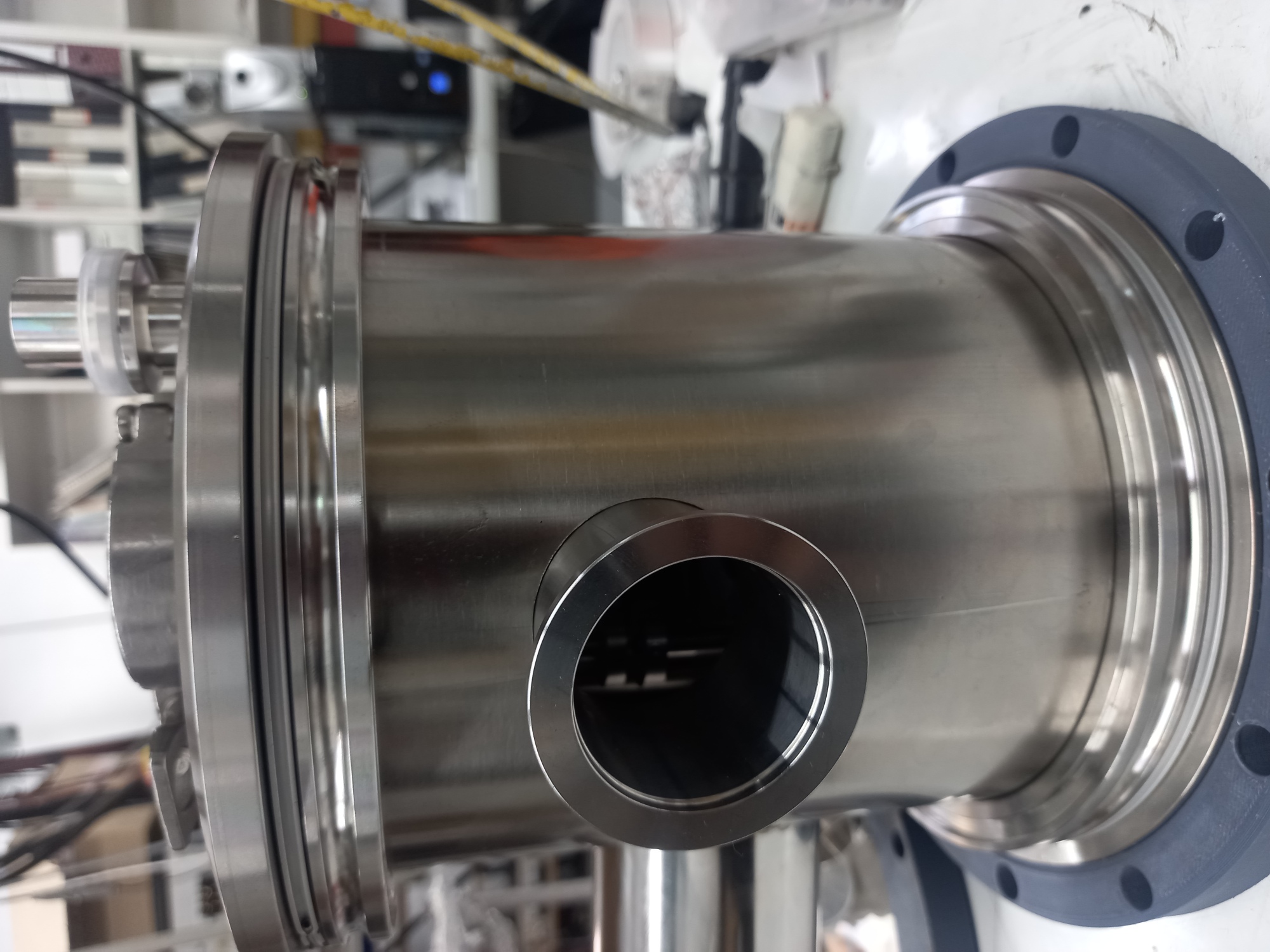
| 14:00, 21 May 2024 | Sap chamber preweld.jpg (file) |  |
651 KB | Seumag | Chamber before welding lateral flanges | 1 |