Power Distribution and Communications Board v1.3
Contents
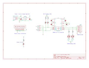
Power and Communications Board v1.3
Note: development on Kicad boards should be done in the electronics/powercomms directory in subversion
Schematic
Changes (Done)
- Add debug LED's to TTL Tx/Rx lines (nophead)
- Add debug LED's to RS232 Tx/Rx lines (nophead)
- Add extra capacitor to filter out high frequency noise as per data sheet (nophead)
- Figure out bug with 78L05 and cvpcb failing. (Zach Smith)
- Change power connector to 12v/G alternating connectors. (Zach Smith)
- Swap 4700uF capacitor for two 2200uF capacitors (Simon McAuliffe)
PCB Layout
TODO List
- Double check silkscreens
- Make .100" holes slightly bigger
Finished
- Move RS232 led's closer to control lines
- Move tx/rx led's to each side of their respective connections.
- Insert new capacitor near 5v regulator
- give the .100 connectors a proper silkscreen for Tx/Rx as well as power.
- Fastener holes: ensure clearance fit for 1/8" (3.125mm) diameter shank (Imperial equivalent of M3). Dia 3.5mm should do it.
- Fastener washer space: ensure circuits avoid the radius of an M3 washer on the fastener holes (metal washers might short the circuit).
- The C6/C8 capacitors are to spec as per the Mouser datasheet.
- Move 1uf capacitor closer to MAX232
General TODO
- Test LED modifications on v1.2.1 board with 'green wire' mods.
Technical Documentation
- PowerComms 1.3.0 2007-08-19 schematic as JPG:
- [[File:PowerCommsBoard 1 3-comms and power distribution-sch.pdf: PowerComms 1.3.0 2007-08-19 schematic as PDF|thumb]]
