Mondrian Build Manual
|
English • العربية • български • català • čeština • Deutsch • Ελληνικά • español • فارسی • français • hrvatski • magyar • italiano • română • 日本語 • 한국어 • lietuvių • Nederlands • norsk • polski • português • русский • Türkçe • українська • 中文(中国大陆) • 中文(台灣) • עברית • azərbaycanca • |
Assembling and setting up the machine should take between 4h to 8h or two afternoons :) If you preassemble everything, or if you disassemble your machine for a travel, it should take 1h to put it back together.
<videoflash>QuMhb-vMsfw</videoflash>
Contents
General tips
Read the whole manual once or twice before starting, to get an overview of the build
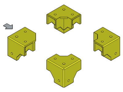
Know the parts
Firstly, have a look at all the part and learn what everything is.

base corner

top corner

top corner (at the rear left, you can embed a raspberryPi pcb webcam in it)
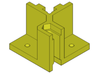
z-slider

z-slider with space to embed the z-endstop
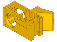
x-slider

y-slider left

y-slider right
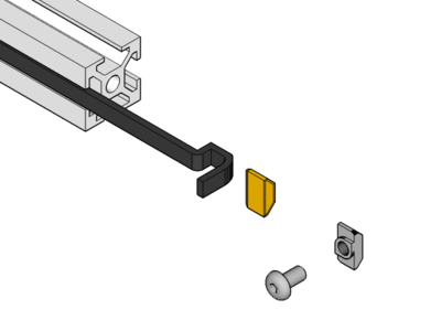
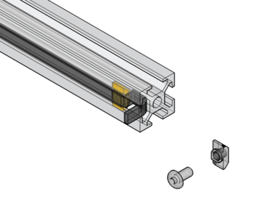
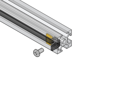
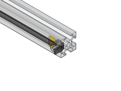
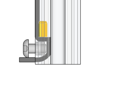
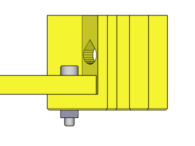
How to insert a T-nut
 Tightening torque : 2.5 Nm (+/- 5%)
<videoflash>9CAiVmfO2mk|320|240</videoflash>
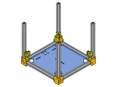
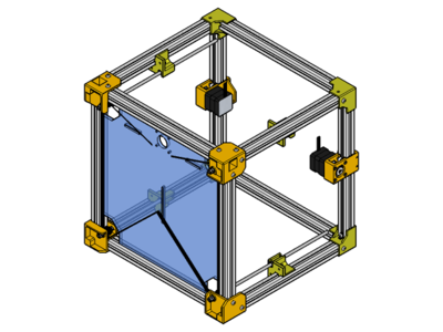
Base frame
 x4 base-corner
 x4 300mm profile
 x4 m4x8
 x4 m4 t-nut


 x4 base corner assembly
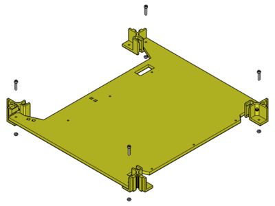
 x1 bottom-plate
x4 m4x8
x4 m4 t-nut
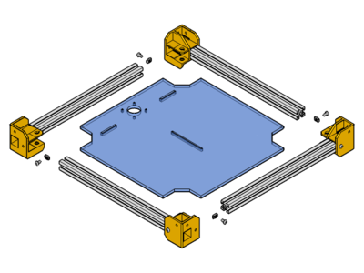

don't lock the nut firmly for the moment
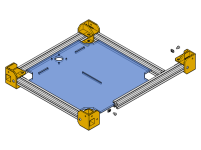
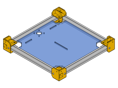

press the sides and check that every corner is square, lock the 4 corners


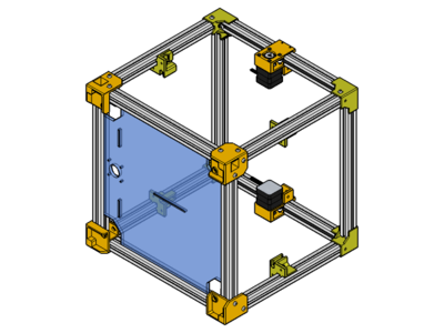
Z-sliders
 x3 z-slider
 x1 z-slider for endstop
x4 300mm profile
x8 m4x8
x8 m4 t-nut
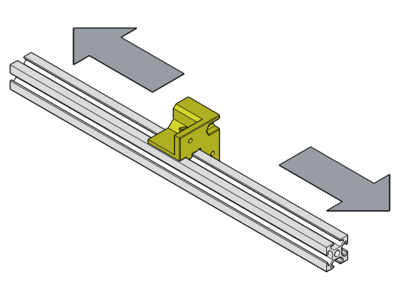
pay attention that each aluminium profile can be a little different, check that the printed part slide well on it, enventually file it

the slider holding the z-endstop will go at the rear left
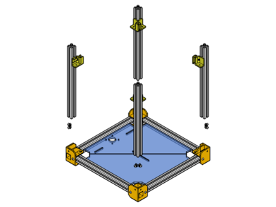
put the t-nut in place first

then the aluminium profile, lock the nut

check that the z profiles are almost square to the base frame (it will be better once the top frame is in place)


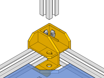
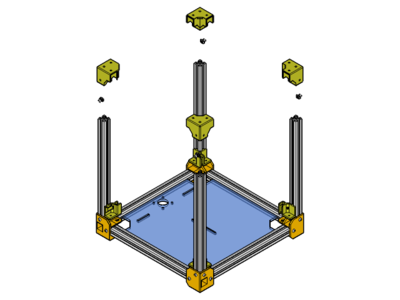
 x3 top corner
 x1 top corner for z-endstop
x4 m4x8
x4 m4 t-nut
the top corner eventually holding the raspberryPi webcam will go at the rear left
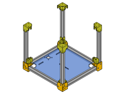


x2 300mm profile
x2 m4x8
x2 m4 t-nut


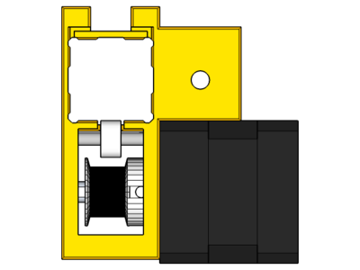
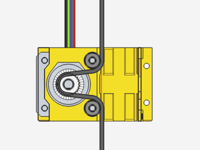
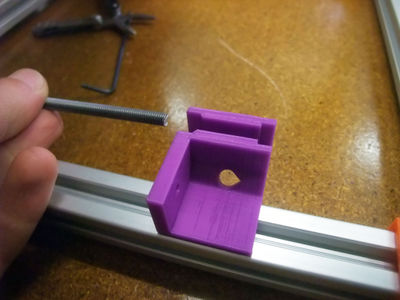
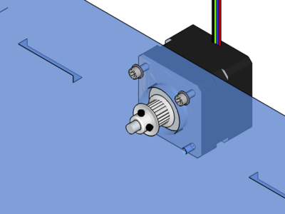
Y-sliders
 Y-slider left
 Y-slider right
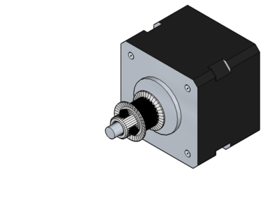
 x2 nema14 stepper motor
 x2 pulley
 x8 m3x30 counter-sunk
 x4 603zz bearing
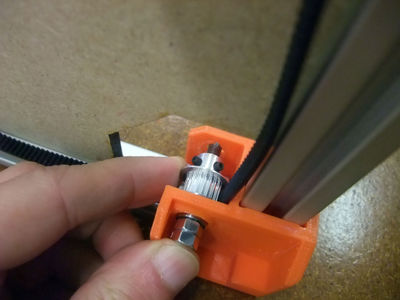
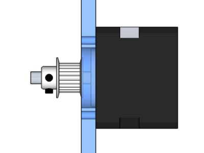
The instruction show the left side, it will be the same (in mirror) for the right side.

pay attention that each aluminium profile can be a little different, check that the printed part slide well on it, enventually file it

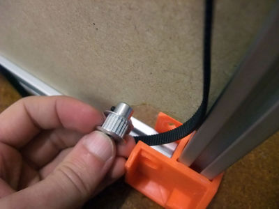
add the pulley on the motof shaft (if you have this pulley you will need to invert it)
check the position of the pulley with the printed part then lock it with the grubscrew


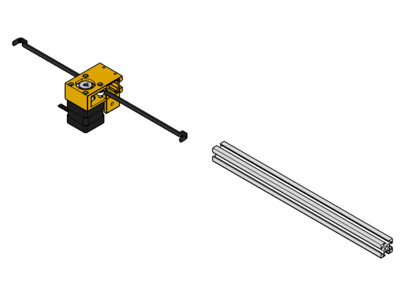
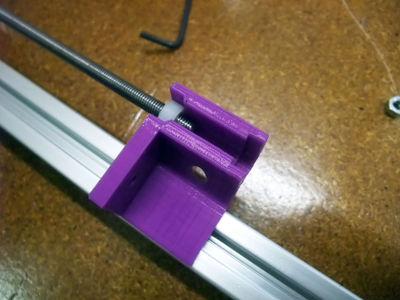
x2 300mm profile
 x2 360mm belt
x4 m4x8
x4 t-nut
x2 360mm belt
x4 m4x8
x4 t-nut
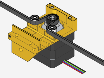

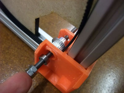
the belt need to be well tightened before locking the second t-nut


x4 m4x8
x4 t-nut


Z-drive
 x1 closed-belt
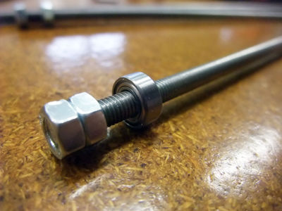
 x4 m5 threaded rod 300mm
 x8 m5 nut
 x4 mr105zz bearing
 x4 pulley
 x8 m5 nylon nut
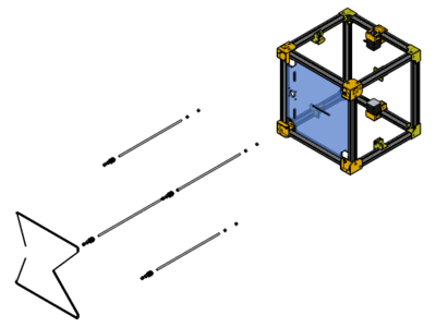
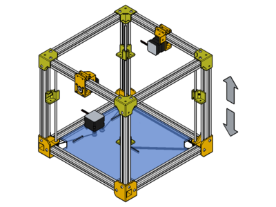
here is an overview, we will assemble one rod at a time while the cube is laying on the side, then turn it and make another rod

lock the m5 nut together at the end of the rod (using two flat spanner #8 or two pliers)
don't forget to add the belt before the pulley
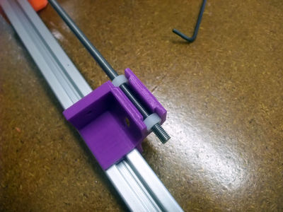

adjust the nuts so that you have no play in Z (between the nuts and the printed part) while the rod still turn easily
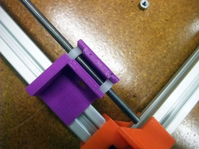

move the z-slider toward the middle
now you can lock the pulley on the Z rod, there should be no play in Z, between the pulley and the printed parts, but it should also turn easily
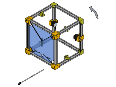
repeat for each corner (turn the cube as it's easier to work on the laying side)


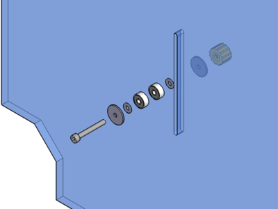
 x1 nema 17
 x6 623zz bearing
 x2 m3x10
 x2 m3x20
 x1 m3x25
 x8 washer
 x4 large washer
 x1 m3 nut
 x1 m3 nut housing

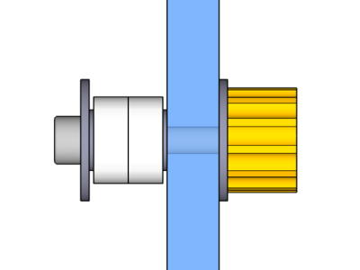
add the pulley on the motor shaft

the pulley should be flush with the panel, lock the pulley

the motor's connector is facing upward (in direction of the rear side of the machine)
start with the two m3x10 and washers
then with the two m3x20 holding the bearings between washers
insert the m3 nut in the printed housing (use a bolt to pull it through if needed)
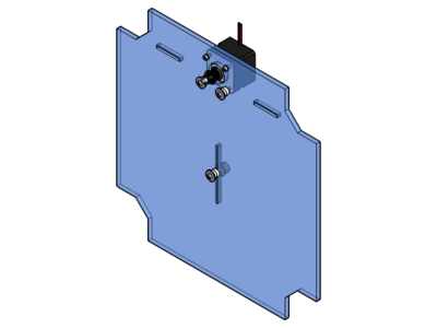
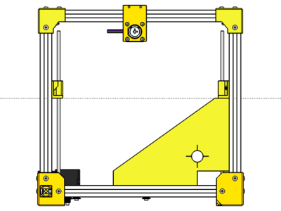
put the four Z-slider at the same height (e.g.: using the square)

now you can tension the belt (caution to keep the z-rod in place, they may turn while you pull on the belt)
check that everything moves well and that the four Z-sliders move in a synchronised way, eventually using the belt or by turning one of the Z-rod

it is not always needed, but if you think a rod could fall off from a z-slider (maybe you need to tighten a nut one face more) you may add a zip-tie to prevent it (or this printed part)


Bed
x1 m4 t-nut
 x1 m4x10


 x1 Z-plate
 x4 m3x16
x4 m3 nut
x4 m3x16
x4 m3 nut
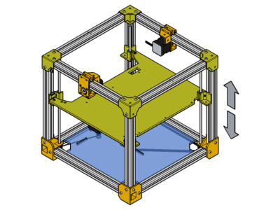
check z-sliding by moving the belt


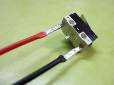
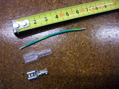
 x1 microswitch
 x2 ferule
 heatshrink tubing
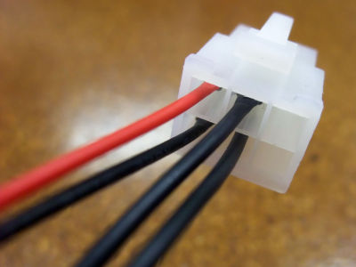
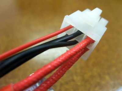
 x1 2pin wire with connector

shorten the 1m wire to 30cm (and save 70cm for the blower)
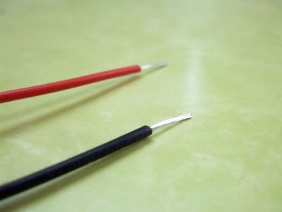
strip the end

don't forget to add a 10mm of heatshrink tubing

add the ferule
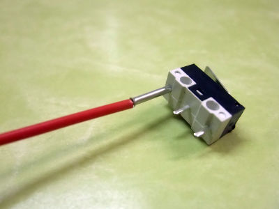
add it on the outer pin

crimp firmly

pull gently to see if the crimping is ok
repeat

push the heatshrink tubing on the ferule
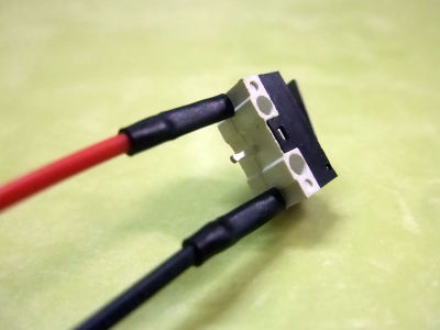
and heat them
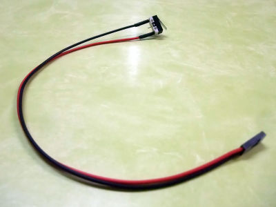

pass the wires first in the z-slider printed piece then push the endstop in place


 x1 bed plate
 x1 film heater
x3 m3 nut housing
x1 film heater
x3 m3 nut housing
x3 m3x35 countersunk head
x6 m3 nut
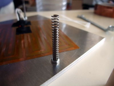
 x3 spring
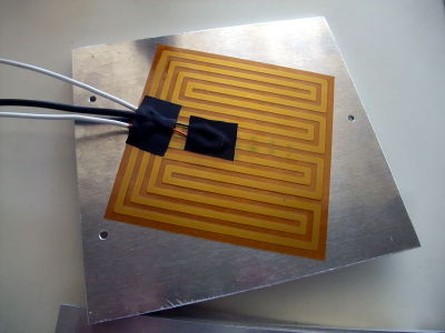
peel of the paper and stick the film heater on the plate
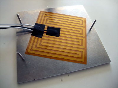
add the 3 countersunk m3x30
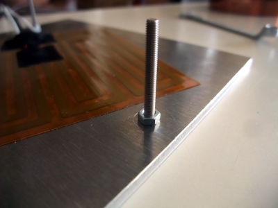
and lock them with m3 nut
insert the m3 nut in the printed housing (use a bolt to pull it through if needed)

place the aluminium bed over the wood bed and fix it with the 3 nut housings...

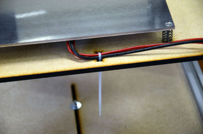
... or 3 bolts (like on the picture) as you prefere; the bottom part of the screws should be aligned with the bottom part of the bolts (the bed level will be adjusted at the end)

add the noodle-cup


Rear Panel
 x1 back panel
 x1 plug
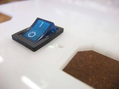
 x1 switch
 x2 m3x8
x2 m3 nut
x2 m3x8
x2 m3 nut

place the switch on the back panel: position OFF downward
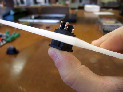
clip the switch on teh back panel
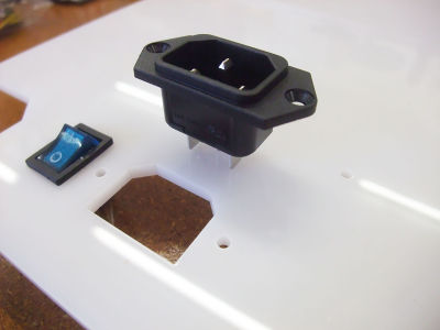

fix the plug with M3x8...
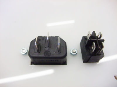
... and M3 nuts


 x3 6,35 ferule (+ insulation)
x4 4,8 ferule (+ insulation)
x3 6,35 ferule (+ insulation)
x4 4,8 ferule (+ insulation)

cut a red wire to 60mm

crimp a 6,35mm ferule on one side of the wire and a 4.8mm ferule on the other side (don't forget to add the insulations BEFORE you crimp the ferules!)
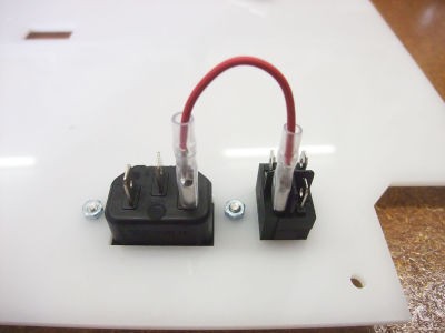
connect the switch (4,8mm ferule) and the plug (6,35mm ferule) with the red wire

cut a black wire to 80mm

crimp a 6,35mm ferule on one side of the wire and a 4.8mm ferule on the other side (don't forget to add the insulations BEFORE you crimp the ferules!)
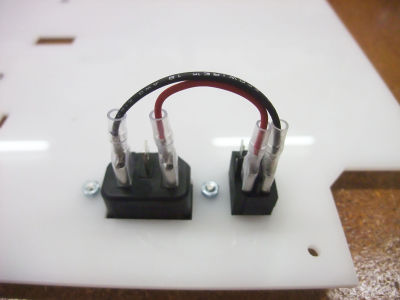
connect the switch (4,8mm ferule) and the plug (6,35mm ferule) with the black wire
cut a green wire to 60mm

crimp a 6,35 ferule on the green wire

do it again with a 60mm red wire and a 4,8mm ferule

do it again with a 60mm black wire and a 4,8mm ferule
connect the switch and the plug with the 3 more wires


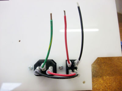
 x1 power supply 150W
x2 m3x8
x1 power supply 150W
x2 m3x8

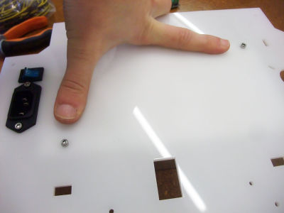
identify on the picture the 2 fixing points

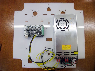
place the power supply above the switch + plug

screw the lower part of the power supply on the back panel with a M3x8

rotate lightly the power supply through the left to make the wiring easier: L>red; N>black; Ground>green

replace the power supply verticaly and screw the upper part of the power supply on the back panel with a M3x8


 x1 minitronics 1.1
 x4 strut
x8 m3x8
x4 strut
x8 m3x8

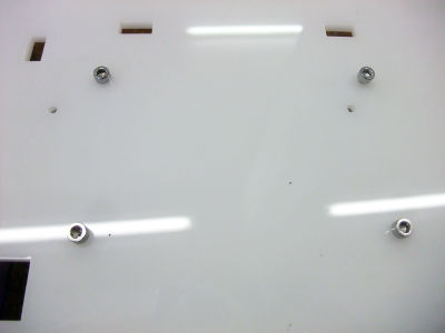
screw the 4 struts on the 4 corners of the electronic board with 4 M3x8

place the electronic board on the back panel (USB port downward)

screw the electronic board on the back panel with 4 M3x8

connect the cables on the electronic board
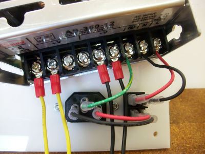
connect the cables on the power supply


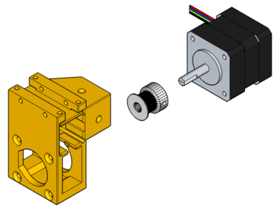
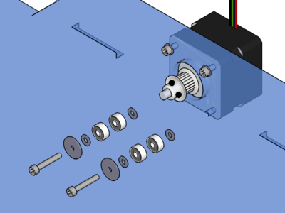
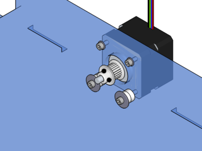
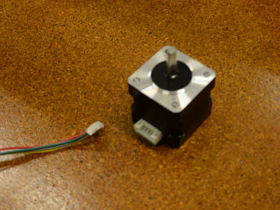
x1 NEMA 17 stepper motor
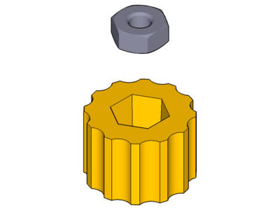
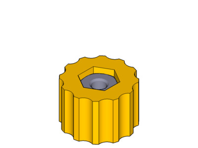
 x1 knurled insert

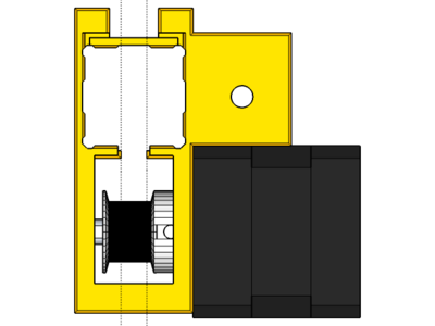
fix the drive gear on the motor shaft

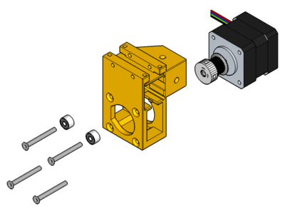
 x1 extruder 17
 x1 pneumatic fitting
x2 M3x10
x1 pneumatic fitting
x2 M3x10
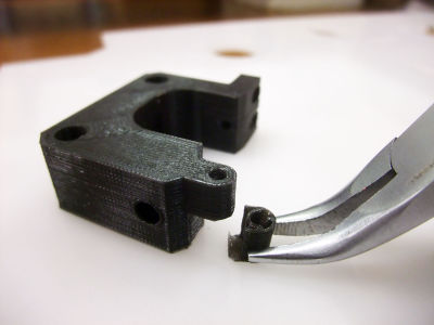
remove the support material of the extruder idler
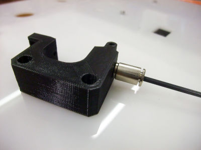
screw the pneumatic fitting in the extruder idler with the 2.5 hexagonal key

place the extruder idler on the back panel with the M3x10 (pneumatic fitting oriented upward - unlike shown on the picture...)

screw the M3x10 in the nema 17 stepper motor through the back panel (cable oriented downward)


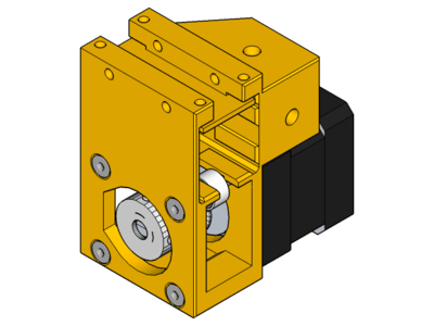
x1 M3x16
x1 603zz bearing
x1 M3x25

remove the support material of the extruder strip

fix the bearing on the extruder strip with a M3x16

assemble the extruder idler and strip with a M3x25 and screw them in the motor through the back panel


 x2 M3x35
 x2 spring
x2 M3 nut
x2 M3 washer
x2 spring
x2 M3 nut
x2 M3 washer

screw the springs on M3x35 to keep the extruder idler and strip tight

x5 M4x8
x5 M4 T-nut

add the screws and nuts on the back panel and fix it on the back of the Mondrian structure

X-axis
- y-endstop
x1 microswitch
x2 ferule
heatshrink tubing
x1 2 pin wire with connector
shorten the 1m wire to 80cm
strip the end
don't forget to add a 10mm of heatshrink tubing
add the ferule
add it on the outer pin
crimp firmly
pull gently to see if the crimping is ok
repeat
push the heatshrink tubing on the ferule
and heat them

pass the wires first in the x-slider printed piece then push the endstop in place

- x-endstop
- blower
- x-slider
 x1 x-slider
x1 nema14 stepper motor
x1 pulley
x4 m3x30 counter-sunk
x2 603zz bearing
x1 x-slider
x1 nema14 stepper motor
x1 pulley
x4 m3x30 counter-sunk
x2 603zz bearing
x1 belt
x2 m4x8
x2 T-nut
- check movement
- prep Y-endstop
- prep X-endstop
- motor+pulley+bearings
- belt
- blower

pass the wires of the X-axis through the RepRap symbol cut on the back panel

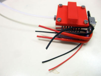
Hotend
 x1 heater block
 x1 nozzle
 x1 barrel
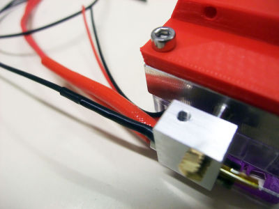
 x1 thermistor
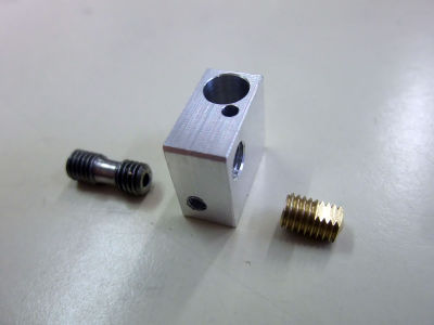
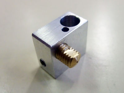
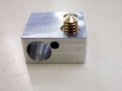
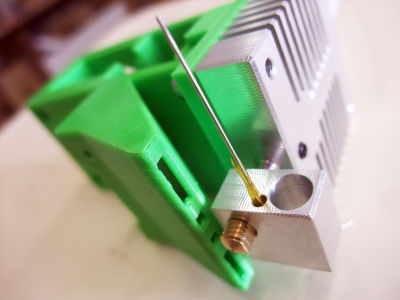
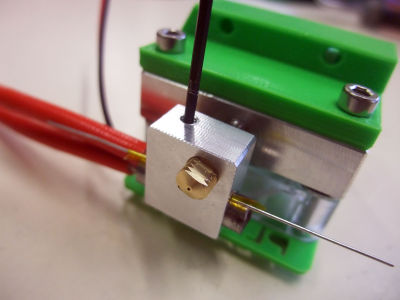
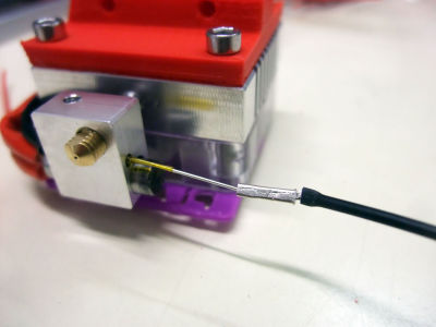
screw the nozzle into the heater block until the nozzle meplat get aligned with the flat part of the heater block
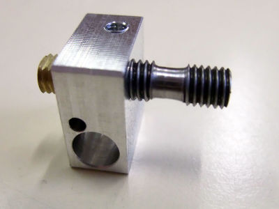
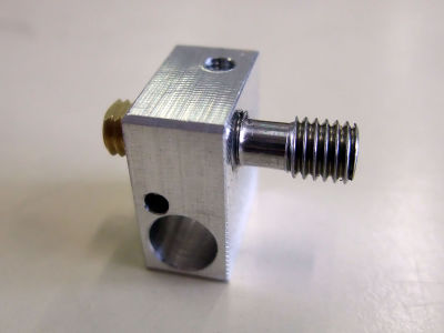
screw the barrel into the heater block until it touches the nozzle
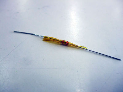
wrap the thermistor with a pice of Kapton...
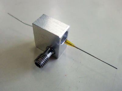
... and place it into the heater block


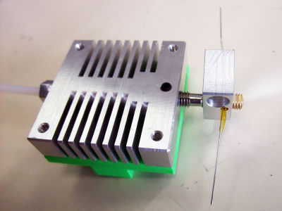
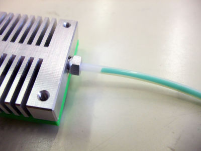
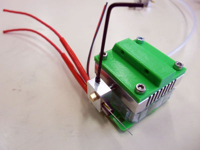
 x1 hotend heatsink (+ tube holder)
 x1 PTFE tube
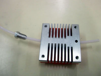
pass the PTFE tube in the tube holder and pass it through the heatsink hotend
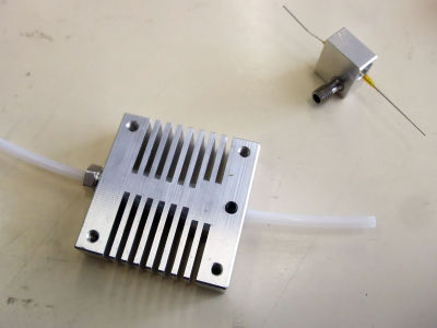
screw the tube holder in the heatsink hotend


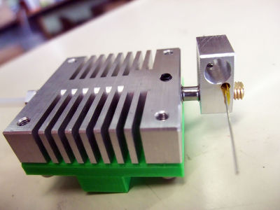
 x1 hotend holder
x4 m3x8
x1 hotend holder
x4 m3x8
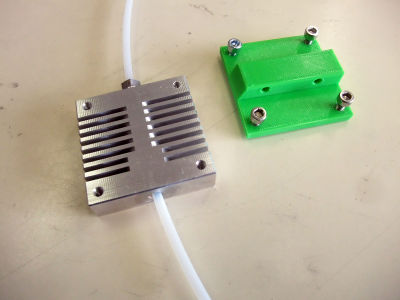
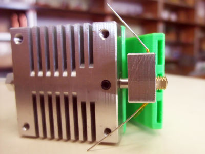
orient the hotend heatsink so that the side with 5 holes is placed on the table (invisible)
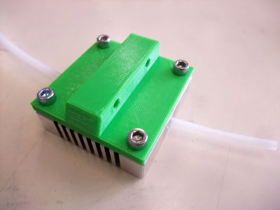
screw the m3x8 into the hotend heatsink (on the side with 4 holes) through the hotend holder
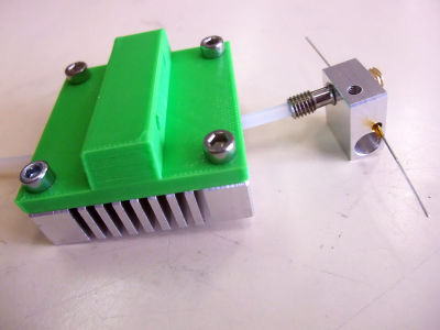
push the PTFE tube in the barrel as much as possible
screw the barrel in the hotend heatsink...
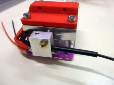
... until the thread is aligned with the bottom part of the hotend heatsink and the edges of both metal parts are parallel (the longer part of the heater block is oriented towards the front of the hotend)


x1 x-slider
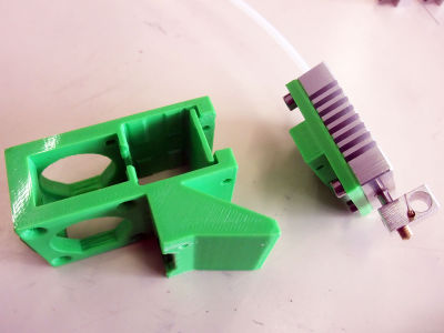
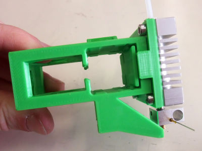
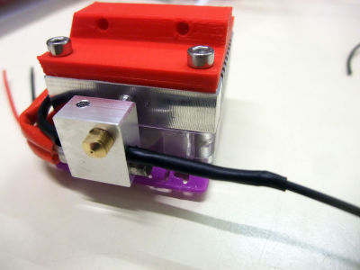
check the alignment of the heater block with the spout of the x-slider
the bottom part of the heater block must be aligned with the upper part of the spout holes
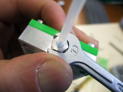
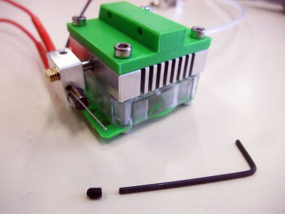
if the alignment is ok then fix the barrel in the hotend heatsink with a grubscrew
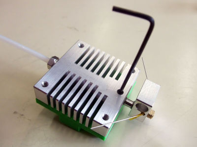
tighten the tube holder on the PTFE tube with a spanner: tight enough so that the tube is hold...
... but not too much so that the filament can still pass through it


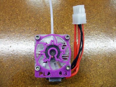
 x1 fan
 x1 fan railings
x4 m3x16
x4 m3 washer
x1 fan railings
x4 m3x16
x4 m3 washer
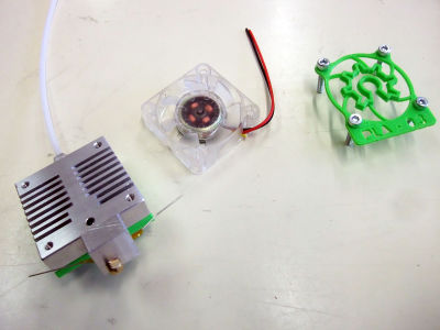
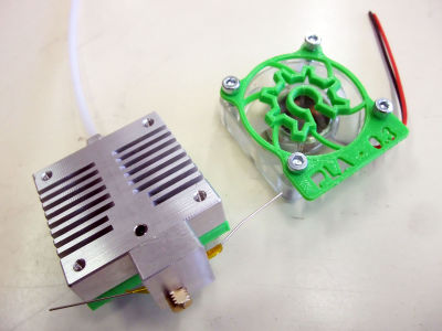
pass the 4 screws through the fan railings and the fan (wires oriented downward)
add the 4 M3 washers...
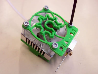
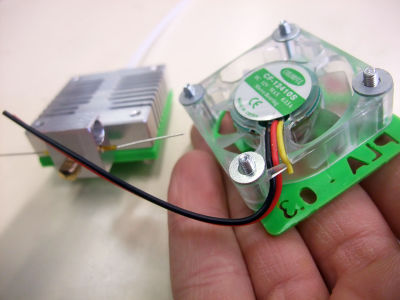
... and screw the elements in the hotend heatsink


 x1 cartridge heater
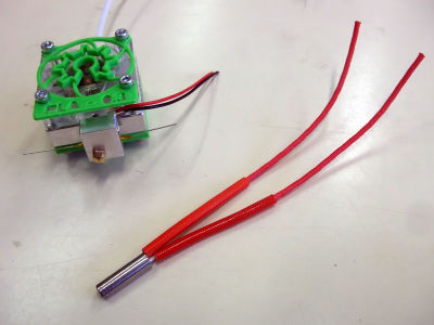
keep 10cm of the cartridge heater wires
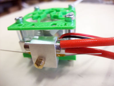
insert the cartrige heater in the heater block so that the wires run along the fan wires
fix the cartridge heater in the heater block with a grubscrew


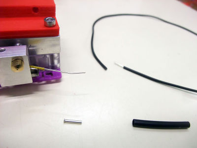
x2 1mm ferule
 x2 heatshrink sleeve
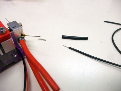
strip one extremity of a black wire
crimp firmly the wire on the thermistor extremity with a ferule
add the heatshrink sleeve over the metal part and heat it with a lighter
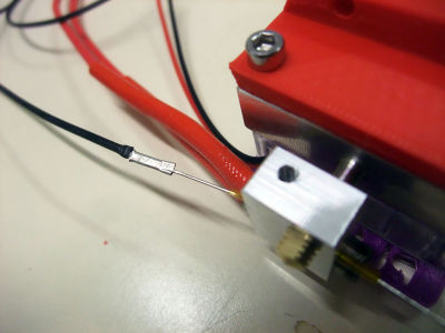
cut the black wire the same length as the cartridge heater wires
once again: strip one extremity of a black wire
crimp firmly the wire on the thermistor extremity with a ferule
add the heatshrink sleeve over the metal part...
... and heat it with a lighter
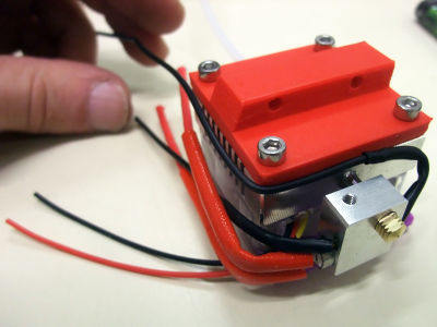
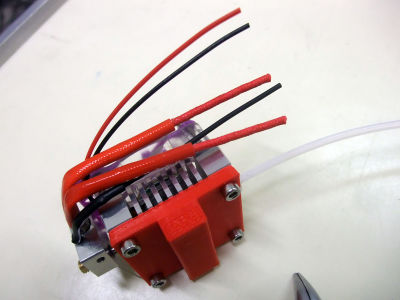
bring the black wire together with the others...
... and cut it the same length as the others
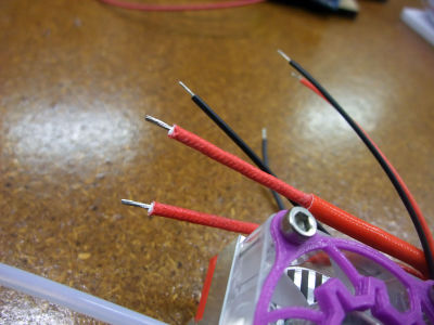
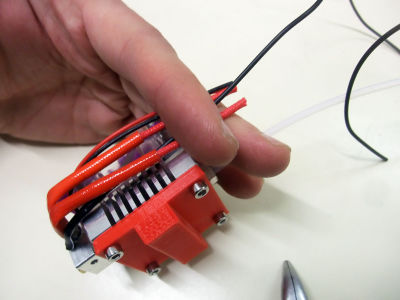
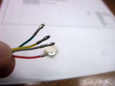
strip the 6 extremities of the wires
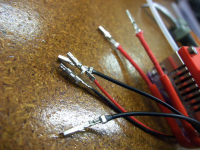
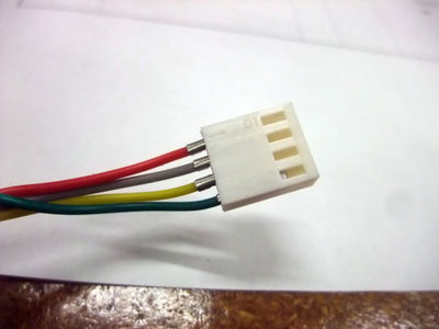
crimp one female ferule on each extremity...
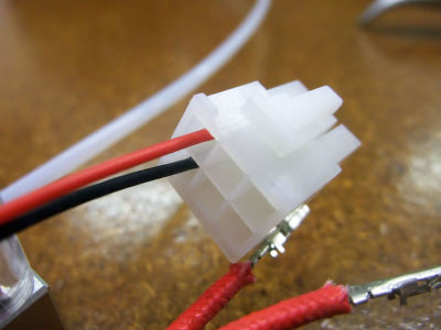
... and insert them in the male casing just like on the picture - 1: fan (red wire on top)
2: thermistor (wires' position doesn't matter)
3: cartridge heater (wires' position doesn't matter)
your hotend is almost ready! you still need to heat the hotend and tighten the nozzle in the heater block as much as possible but you first have to do the wiring...


Wiring
wire the 5 motors with their corresponding cables

X-motor (long); Y-motor 1 (long); Y-motor 2 (long); Z-motor (short); E-motor (short)


bring the wires from Y-motor 2 out of the connector related with the electronic board and invert them
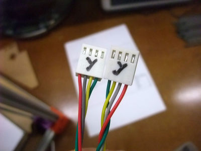
bring the wires back in the connector


connect the different electronic elements on the minictronics like shown on the picture (pay attention to the wires color)

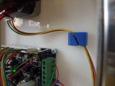
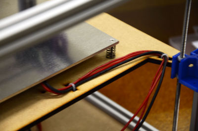
tidy the wires by passing them through the 4 cable holders

zip-tie the bed wires on the wood panel


- bed ok
- back panel ok
- x-axis ok
- hotend
- y-motors+led
Calibration
- config file to use (board)
- making the bed parallel
- config file to use (software)
- then
- elec cover + fan (File:Fan404010.png + m3x16 + m3nut)
- side panels
- door
- celebrate