Delta Rostock mini G2s
| |
Not Open Source
As stated in the RepRap Wiki Policy, a wiki page that describes a product offered for sale must provide source files for that product. This page is missing at least these item(s)
There might be more items missing. If you want to help improve this design, please find source files for these missing items and upload them to this wiki, or link to the repository containing them. In accordance with the Deletion policy, an admin will review this page in about three weeks to determine if it should be removed or not. If source files are not uploaded by the proposed delete date, this page will be removed from the wiki. Proposed delete date: {{{deletedate}}} Questions about this tag can be addressed on this page's discussion page or on the Administration, Announcements, Policy forum. |

This Rostock mini G2s is a companion piece of our new upgraded delta 3D printer -Rostock mini G2. G2s is designed to support dual extruder. With G2s you can print a single two-color object, or you can print two objects in one print job, each made from a different color. You can also print one single-color object, as with other single-extruder 3D printers. Or you can use one extruder for infill or support. The 2 extruder motor pushes filament through 2 head separately, so mixing colors printing is not applicable for the moment. This G2s is powered by our newly designed control system—GT2560 that supports 2 extruders and eliminates the complicated wiring of Mega2560+Ramps 1.4 and it is more space-saving. An auto-leveling auto-calibration device is also added on G2; which means you do not have to adjust it every time before you start printing, after the first assembly work, you can almost plug and play. In terms of printing filament, G2s not only support PLA and ABS, Nylon and wood filament is also available, which enables more possibilities to create 3D printing project. This G2s is also improved with LCD control panel; you can monitor the printing process in real time and with a SD card it can realize stand-alone printing, very convenient.
Contents
- 1 Main features:
- 2 Specifications:
- 3 BOM
- 4 Sources
- 5 Building Instruction
- 6 Assembly Tips
- 7 Building Modifications
- 8 Troubleshooting
- 9 set up
Main features:
1. With dual extruder, support multiple way of printing.
2. Support PLA, ABS, Nylon and Wood, giving more possibilities to create 3D printing project.
3. New updated control system.
4. Auto-leveling and auto-calibration.
5. More flexible effectors and diagonal rods.
6. More fluent printing process and higher precession.
Specifications:
Print Volume: 170 x 200mm
Chassis: laser -cut acrylic plate
The Layer Thickness: 0.1mm
Layer Resolution: 0.1mm
Filament Diameter: 1.75, 3mm
Nozzle Diameter: 0.3, 0.35, 0.4, 0.5mm
Print Speed: 60 to 120 mm/sec
Print Plate Size: 210 x 3mm
Print Plate (Build Platform): aluminum plate + heatbed
XYZ Bearings: carbon steel
Stepper Motors: 1.8° step angle with 1/16 micro-stepping
Max Heated Bed Temp: about 110 ℃
Max Extruder Temp: about 240 ℃
AC Input: 115V/1.5A 230V/0.75A
Output:DC12V/0-15A
No. of Extruders: 2
Connectivity (Interface): USB, SD Card
Electronics: GT2560
3D printing Software: Repetier Host
CAD Input data file format supported: STL, G code
Client Operating System: Windows, Linux, Mac
Machine Dimensions: 320 x 320 x 870mm
Machine weight:9kg
Shipping box dimensions:495*395*195mm
Shipping box weight:10kg
BOM
download the BOM here Media:Delta Rostock mini G2 Package List.pdf
Sources
Download the .STL file for the printed part here
The laser cut file is not avainable for the moment, we will share them later, please stay tuned.
Building Instruction
For detailed building instruction, please visit here.
You can also download the PDF version here Media:Delta Rostock mini G2& G2s building instruction.pdf
Assembly Tips
These assembly tips are community provided, and are not official Geeetech recommendations.
Use at your own risk. If in doubt, contact Geeetech directly for supported assembly assistance.
Driving Pulley Attachment
After tightening the primary screw against the flat of the motor shaft, either remove or fully tighten the remaining screw in the pulley.
Failure to do so will allow the screw to wiggle loose during printing, and will case the pulley to jam against its acrylic enclosure.
Initial Bed Levelling (during build)
During bed installation, use a reference height (such as a M3x12 bolt from bag 18) to make sure that each top of each bed mounting point is the same after tightening the wingnuts.
Simply place a M3x12 bolt (head down) next to the bed (not under!), and tighten until the end of the bolt it at the same level as the top of the bed. Repeat for the other two mounts.
Z-Probe Switch and Rod-End Bearing Installation Order
The G2/G2S Build Manual (as of Sept 4, 2015) has the Z-Probe Switch installation procedure before the Rod-End Bearings procedure.
If done in that order, the Z-Probe Switch will prevent the installation and tightening of the Rod-End Bearing retaining bolts.
Reorder the building instructions as follows:
- Proceed through the manual until you reach the Z-Probe and Switch installation section.
- Skip ahead, and install the Spider's Rod-End Bearings (but not the Diagonal Rods themselves)
- Return to the Z-Probe and Switch installation chapter.
- Continue instructions as per normal from the point after the Z-Probe Switch installation
Z-Probe Switch Installation
For the Z-Probe switch, you are required to screw through both the switch and the spider with the M3 retaining bolt.
Before installing on the spider, screw both bolts through the switch until the ends are flush with the opposite side of the switch.
When installing on the spider, tighten each bolt a 1/4 turn at a time, until both bolts have begun to screw into the spider, then tighten normally.
There should be no more than a 1mm gap between the Z-Probe Switch and the spider.
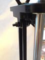
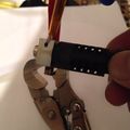
Smooth Rod Tightening
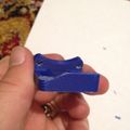
It can be difficult to tighten the lubricated smooth rods by hand. If you have a pair of vice-grips, you can pad the jaws (foam or cloth to prevent scratches to the smooth rods) and clamp down tightly.
Vice-grips padded with foam to prevent scratches.

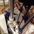
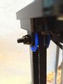
Idler Pulley
Tighten the retaining bolt
It is of critical importance to fully tighten the bolt in the middle of the sheet metal U holder for the idler pulley.
If the bolt is not fully tightened, when the wingnut is used to secure the pulley, it can cause the bolt to back out slightly, and press against the belt. This can then cause the belt to jam, and cause a head crash.
Tighten the wingnut
The wingnut cannot be used to adjust belt tension (unless you use the 'Idler Pulley Guide' modification). The wingnut must be fully tightened, or the sheet metal holder can 'lean' slightly, and cause the belt to jam against the pulley holder.
Adjust belt tension by loosening the wingnut, changing the belt notch that is held by the carriage belt retainer, then fully tightening the wingnut.

Note the canted idler pulley, and the belt jammed against the sheet metal idler pulley holder.

Cable Tidying
Endstop Cabling
When tidying the cable, it is good practice to separate the signal cables (endstops) from the driving cables (extruder control and fans).
Twist each endstop wire. This will reduce the noise that can be picked up the cable.
Then, put all three endstop cables in a separate wire bundle from the extruder stepper and fan cables.
Although Marlin firmware (the default shipped with the G2/G2s) appears to only check the endstop signals while homing, other firmwares (such as Repetier) check the endstop signals continuously, and will cause layers to shift in the X/Y plane if an endstop signal is too noisy, especially on fast extruder operations such as retractions.
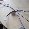
Endstop cable, as shipped.
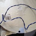
Endstop cable, twisted to resist noise.


Building Modifications
The following are community provided modifications to the Geeetech Delta Rostock G2/G2S, and are not supported by nor approved by Geeetech. Use at your own risk.
Adjusting the Bed Levelling From The Top
If you have especially slippery acrylic, you may find that the wingnuts may spin when you try to adjust the bed height via the recessed bolts in the bed.
If you have this issue, place a M3 lock washer (not included in the Geeetech kit) under the wing nuts, to prevent the wing nuts from spinning.
Z-Probe Lock Ring
If you have problems with the Z-Probe lock ring slipping, or are worried that your will strip the plastic threads in the lock ring while tightening the jam bolt, simply file a flat into the Z-Probe at the location where the lock ring will be.
Then, the lock ring will be unable to slip.
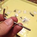
Z-Probe after the flat has been filed into it with a rectangular rasp.

G2S J-Head Orientation
The G2S build documentation leaves the orientation of the J-Head up to the user. Many different orientations are possible.
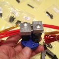
For balance (wiring feeds to both sides) and ease of maintenance (thermal block set screw accessible on both heads), use this orientation.
Unfortunately, the fan mount will be touching the lower J-Head in this setup.
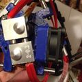
Trim down the interfering area of the fan mount with a craft blade.
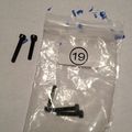
Replace the bolt for the modified mounting hole with a M3x16 (Bag 19, or hardware store)
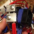
Final mount - note the 1mm~2mm gap between the lower J-Head and the fan mount.


Frame Tightness Solution
If your frame is wobbly, the problem may be that the acrylic base plates are slightly thinner than specified.
To check, use a caliper to measure the thickness of the top and bottom acrylic base plates.
If they are in spec (8mm or slightly thicker) then do not perform this modification - your frame issues are elsewhere.
If your base or top acrylic plates are thinner (for example, in my G2S the base plate was 8mm, but the top plate was 7mm), you will be able to feel the end of the smooth rod slightly protruding through the acrylic, instead of inset, as required to stiffen the frame.
To resolve this issue, remove the suspect acrylic plate, and replace the single M8x1mm washers on the smooth rod ends with either two M8x1mm washers, or a single US 5/16th" x 1/16th" (approx 8mm x 1.5mm) washer. Note that all of the washers for the plate must be identical.
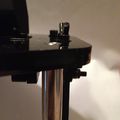
Note the smooth rod slightly protruding above the acrylic.
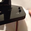
After the washers have been replaced, the rod is slightly inset, to allow the frame to be tensioned to the rod by the retaining bolt and washer.


Belt Jam at Idler Pulley Solution
If you are getting jams at the Idler Pulley, first verify that:
- The idler retaining bolt is fully tightened - if not, it can back out when the wingnut on the idler pulley is tightened, and jam against the belt.
- The idler retaining wingnut is fully tightened - if not, the idler pulley can end up at a slant, and the belt will jam against the idler pulley holder.
- The belt is fully inserted into the carriage belt retainer - if not, the belt will angle towards the idler pulley, and can jam against the idler pulley retainer.
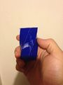
If you have checked all of those and still have issues with belt jams, print out this File:Delta Rostock mini G2s MOD idlerpulley guide.stl (originally from Thingiverse user Gidim) 6 times, and insert it on the idler pulley bearings, between the belt and the idler pulley housing.
They should take under 3 minutes to print at 0.3mm layer height and 25% infill, if you print all 6 of them at a time. If you have issues with stringiness or other quality issues, print as many as you can fit on the bed, and pick the best 6 to use.
Belt that tended to jam, due to being unable to fully insert the belt into the carriage belt retainer.
Idler pulley guides installed - no more jams.


Repetier Firmware Configuration
This is my (Ezrec's) first cut at a Repetier firmware config (0.91).
NOTE: If your Z Probe has any side to side or back to front wiggle, do not use autoprobing! Your head will tilt and slide all over the place, and you may damage your nozzle.
NOTE: This firmware config was built for a RAMPS 1.4 hardware, and has not been tested on the GT2560 controller. Use at your own risk.
Firmware config for Repetier 0.91: File:Delta Rostock mini G2s MOD Repetier 0.91 Configuration.h.
This configuration file has the full JSON config in it, so feel free to feed it back into Repetier's web-based configuration generator to build a firmware for a different version.
Troubleshooting
J-Head Leaks
If plastic oozes out between the PEEK cold region and the metal hot end, you may need to heat-tighten the J-Head.
First, a note of warning - until you have verified and calibrated the operation of your hot end/thermistor combination, DO NOT SET THE EXTRUDER ABOVE 200C.
Without the active cooling fan, the PEEK cylinder could begin to melt at approx 240C. If you have a poorly calibrated thermistor, you can easily exceed 240C if you set the hot-end temperature above 220C. To be safe, set the hot end to at or below 200C.
Since PEEK slightly expands when heated, if the J-Head was too cold when initially assembled, the PEEK threads will loosen once the PEEK reaches target temperature, and will allow plastic to ooze out between the threads.
The solution is as follows:
- Heat the J-Head up to approx 200C (using your G-Code sender, RepetierHost is what Geeetech suggests), and let it "soak" at 200C for approx 5 minutes.
- Using a vice-grip on the metal heater block of the J-Head (making sure not to clamp onto the nozzle!), loosen the heater block by a quarter turn
- Wipe off any excess plastic from the heater block and PEEK cylinder with a dry paper towel.
- Be careful not to wipe the nozzle - you can easily plug up a 0.3mm nozzle with paper fibers.
- Tighten the heater block to a snug fit.
Do not over-tighten the J-Head! A snug fit is all that is needed - too much force will break the PEEK threads and destroy the head.
NOTE: For the G2s model, you may need to disassemble the spider's J-Head holder to be able to loosen and tighten the heater block.
Although the top of the PEEK cylinder is cool to the touch, the bottom is very hot. Use a vice-grip to hold it while tightening.

G2s Misaligned Hot Ends
If you are getting prints on a G2s where the second extruder's hot end is hitting your print, then the one of your hot ends needs to be tightened.
This is especially visible on spiral-vase prints, and a spiral vase is a great object to use for this type of calibration. Make sure to have both hot ends heated, so that you can see a blemish, instead of the interfering hot end causing a mechanical jam!
If your left extruder is hitting the print while the right extruder is extruding, tighten your left extruder's hot end 1/8th of a turn.
If your right extruder is hitting the print while the left extruder is extruding,tighten your left extruder's hot end 1/8th of a turn .
Spiral vase print with a blemish. Note the glob-line where the non-printing extruder's hot end interfered with the part on every pass.

set up
for detailed set up instruction, you can see at here.