Stepper motor

Contents
What is a Stepper Motor ?
Stepper motors are an electric motor used in the robotics industry. Stepper motors move a known interval for each pulse of power. These pulses of power are provided by a stepper driver and is referred to as a step. As each step moves the motor a known distance it makes them handy devices for repeatable positioning.
There are two major types of stepper motor known as bipolar and unipolar. Wikipedia has further information on stepper motors. Please see Wikipedia.
Terms
Nema - refers to the size of the motor. It specifies the “face” size of the motor but not it’s length. For example a Nema 23 stepper has a face of 2.3 inches by 2.3 inches with screw holes to match. Note just because a motor is bigger does not mean it is more powerful in terms of torque. It is perfectly possible for a Nema 14 to “out pull” a Nema 17 or a Nema 23.
Bi polar and uni polar- These terms refers to the internals of the motor. Each type has a different stepper driver circuit board to control them. In theory a reprap could use either but in practise most are bipolar.
Bipolar Motors

These motors are the strongest type of stepper motor. You identify them by counting the leads - there should be four or eight. They are also the type of motors we are using in the RepRap Project's Darwin design. They have two coils inside, and stepping the motor round is achieved by energising the coils and changing the direction of the current within those coils. This requires more complex electronics than a unipolar motor, so we use a special driver chip to take care of all that for us. Some designs (the eight-wire ones) split each coil in the middle so you can wire the motor either as bipolar (short the middles) or unipolar (short the middles and treat the link as the centre tap - see below).
Unipolar Motors

Unipolar motors have two coils, each one has a centre tap. They are readily recognizable because they have 5, 6 or even 8 leads. It is possible to drive some unipolar motors as bipolar motors if you ignore the centre tap wires. Their main beauty though is that you can step them without having to reverse the direction of current in any coil, which makes the electronics simpler. Some early RepRap prototypes used this trick. Because the centre tap is used to energise only half of each coil at a time, unipolar motors generally have less torque than bipolar motors.
History
Stepper Motor History for repraps Darwin (V1.0 reprap)
The darwin reprap type used a Nema 23 stepper motor. This stepper motor was a unipolar stepper motor which could be configured as a bipolar. This design used 3 stepper motors for each axis and a DC motor for it's extruder. Later many people upgraded their extruders to increase their control of the extruder.
Note the Generation 2 electronics supported the first configuration with 3 stepper driver circuit boards for the steppers and a PWM circuit board to control the DC motor.
The Darwin Stepper Motor Requirements were as follows:
| Parameter | Specification |
| Size | NEMA 23 |
| Type | Bipolar |
| Shaft | dual-output shaft |
| Torque | 100 oz-in or abount 0.71 Nm |
| Resistance | about 10 ohms, or 1 to 30 ohms |
Note
If you are using the PIC controller (Note: Generation 1 electronics) you need a motor that will use about 1A per winding at 12v, that is - around 10 ohms. The Arduino circuit can be adjusted to accommodate a wider range of steppers, but remember that if you specify a low-resistance one and the Arduino controller has to chop the voltage to limit the current going through it, that will also limit the torque.
Stepper Motor History for repraps Mendel (V2.0 reprap)
The Mendel reprap type used either a Nema 17 or a Nema 14 Bi polar stepper motor. It uses four stepper motors. One for each axis and one for the extruder.
Note this configuration of four stepper motors was supported by the 3rd generation electronics.
The Mendel Stepper Motor Requirements were as follows:
| Parameter | Specification |
| Size | NEMA 17 or 14 (prototype was Nema 14) |
| Type | Bipolar |
| Shaft | dual-output shaft |
| Torque | 13.7 N-cm (that is 1400 g-cm or 19.4 oz-in) |
| Resistance | ? |
Holding Torque
It is recommended that you get approximately 13.7 N-cm (that is 1400 g-cm or 19.4 oz-in) of Holding Torque (or more) to avoid issues, although one stepper with less has been used successfully (see below). If in doubt, higher is better. If you need to convert between different units for the torque you can use the torque unit converter here.
Stepping Angle
Most stepper motors used for a Mendel have a step angle of 1.8 Degrees. It is sometimes possible to use motors with larger step angles, however for printing to be accurate, they will need to be geared down to reduce the angle moved per step, which may lead to a slower maximum speed.
Size
If going for the smaller NEMA 14 motors, aim for the high torque option. NEMA 14s are neater, lighter and smaller, but can be hard to get hold of with the appropriate holding torque. NEMA 17s are quite easy to get in the specification that Mendel needs, but are bulkier and less neat. NEMA 14s are running near the edge of their envelope: they will get warm. NEMA 17s are well inside what they can do, and will run much cooler.
Note that any Mendel part that goes on to a Stepper Motor shaft expects the shaft to be roughly 5mm. If the shaft is a different size, you will need to make allowances for this in the parts you obtain/make.
Wiring
Steppers motors come in several wiring configurations. 4,6, and 8 wires are all fairly common. 5-wire version have been reported to exist. 5 wire versions won't work, the others will. See stepper wiring for more details.
Suppliers
Below is a list of possible suppliers and motors. Please add to it. If you have built a Mendel successfully with a given motor, remember to put true in the tested field.
| Vendor (with link) | Shipping location | Manufacturer | Model # | Datasheet | NEMA (Size) | Holding Torque | Shaft | Tested | Additional notes |
| Motion Control Products | ? | Fulling Motor | FL35ST36-1004B | FL35ST36-1004B Datasheet | 14 | ~13.7 N-cm | Dual | true | Used in mendel prototype |
| Active Robots | UK | Wantai | 35BYHG04 | 35BYHG04 Datasheet | 14 | ~12.3 N-cm | 4.9mm | true | Less Holding Torque than recommended, but has apparently been used successfully |
| Pololu | US | SOYO | SY35ST36-1004A | ? | 14 | ~13.7 N-cm | 5mm | ? | Note: Pololu list this motor as 1400 g-cm AND as 20 oz-in (converts to 19.44 oz-in). According to supplier information, the metric value is correct. |
| Vendor (with link) | Shipping location | Manufacturer | Model # | Datasheet | NEMA (Size) | Holding Torque | Shaft | Tested | Additional notes |
| Zapp Automation | UK | SOYO | SY42STH47-1206A | SY42STH47-1206A Datasheet | 17 | ~31.1 N-cm | Single | true | None |
| Zapp Automation | UK | SOYO | SY42STH47-1684B | SY42STH47-1684B Datasheet | 17 | ~43.1 N-cm | Dual | true | Round Ø5mm Shafts |
| Zapp Automation | UK | SOYO | SY42STH47-1684A | SY42STH47-1684A Datasheet | 17 | ~43.1 N-cm | Single | ? | D-Shape 5mm shaft with 4.5mm flat |
| Cool Components | UK | Mercury Motor | SM-42BYGH011-25 | SM-42BYG011 Datasheet | 17 | 23 N-cm | 5mm | ? | None |
| Interinar Electronics, LLC | US | Oriental Motors | Vexta PX243M-01AA | PX243M-01AA Datasheet | 17 | 15 N-cm | Single | ? | Not strong enough for direct drive extruder, Uses Imperial #4-40 TPI mounting holes instead of M3 metric |
| Alltronics.com | US | Lin Engineering | 4218L-01-10 | 4218L-01-10 Datasheet | 17 | ~53 N-cm | 3/16 inch = 4.7625 mm (Round) | true | None |
| Alltronics.com | US | Lin Engineering | 4218L-01-11 | 4218L-01-11 Datasheet | 17 (?) | ~53 N-cm | ~5 mm = 0.1968 inches (D-Shape) | true | None |
| Phidgets.com | US | Wantai | 42BYGHW811 | 42BYGHW811 Datasheet | 17 | ~47.1 N-cm | 4.9mm | ? | None |
| SparkFun | US | Mercury Motor | SM-42BYG011 | SM-42BYG011 Datasheet | 17 | 23 N-cm | 5mm | true | None |
| Robot Gear | AU | Mercury Motor | SM-42BYG011-25 | SM-42BYG011 Datasheet | 17 | 23 N-cm | 5mm | true | None |
| Mindkits | NZ | Mercury Motor | SM-42BYG011 | SM-42BYG011 Datasheet | 17 | 23 N-cm | 5mm | true | None |
| AusXMods | AU | Rugao Xinhe | 17H185H-04A | ? | 17 | ~43.8 N-cm | ? | ? | None |
| Kysan | China | Kysan | 42BYGH4803 | Datasheet | 17 | 49 N-cm | 5mm | true | Successfully tested with Wade's Geared Nema 17 extruder - high flow rates. |
Unscientific rules of thumb for motor purchases
1) The longer the motor body generally the more torque the motor has.
2) If a motor is rated 2.5A and your stepper driver produces only 2A your motor may not produce the manufactures rated torque.
3) If a motor is rated 35 volts and your stepper produces only 12 volts your motor may not produce the manufactures rated torque.
4) A motor can exceed it's rated voltage but will produce more heat. This may not be a problem in Bath/England but may be a problem in warmer climes.
5) Stepper Motors should not exceed 65c.
6) ABS melts at 120C but softens at 80C.
7) Power is measured in Watts and is calculated at Volts X Current.
8) Power made available to a motor will be turned into heat and motion.
9) The more power made available to the motor the higher the amount of heat and motion.
10) Power and torque are related. The more power the more torque.
Driving those motors
Open Source Stepper Motor Drivers
RepRap Stepper Motor Driver v1.x
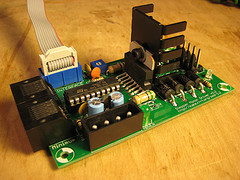
The first generation of RepRap stepper motor drivers. (Note: These boards were used in the generation 2 collection of electronics.) Uses the L297/L298 stepper motor driver combo. Half-stepping. Handles up to 2A. All through hole. A nice, solid driver. It uses some old technology, so its not as fancy as the newer stepper drivers, but it gets the job done. Read the documentation page here.
RepRap Stepper Motor Driver v2.x
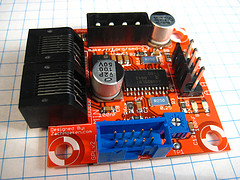
The second generation of RepRap stepper motor drivers. (Note: These boards were used in the generation 3 collection of electronics but could be retrograded to generation 2)
Uses the Allegro A3982 chip which does a bunch of nice things and makes the board much simpler. It also drops the price by $10 compared to the v1.x series. It can handle up to 2A, does half-stepping. The only downside is that its SMT, which can be a bit scary for people. Its all large SMT parts, so its pretty simple to solder it, especially with the solder paste / hotplate method. Read the documentation page here.
AVRSTMD
AVRSTMD - An open source microstepping driver that uses an atmega168 and current limited h-bridges. Very rad circuit.
WARNING
The infomation below is given for reference purposes only and was taken from a previous wiki page. The specs of stepper motors can change. Always check with the supplier's specification. This data could well be out of date.
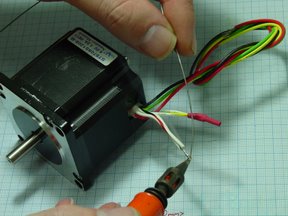
Wiring Your Stepper
Pretty much all of our RepRap electronics are designed for Bipolar stepper motors. Every bipolar stepper motor has 4 wires that need to be wired to the driver board. These are labeled A, B, C, and D for lack of better terms. A and B are connected, as well as C and D. You can generally find out which wires are connected using a multimeter to measure the resistance. If you measure a small resistance (1-30 ohm) then they are connected. Generally, they are color coded and we have datasheets available, so things are easy.
NEMA 17 Motors
Lin Engineering / 4118S-62-07
File:Cache-stepper-motor-nema17.jpg
This is an awesome little NEMA17 stepper motor. It is the primary motor used on the Cupcake CNC. It has good torque and a small size. Here are some of the specs:
- 200 steps per revolution (1.8 deg/step)
- 2.5A / phase
- Phase Resistance: 0.6ohm
- Phase inductance: .93mH
- Holding torque: 3240g-cm or about 0.31 Nm
- Shaft diameter: 0.190"
- Shaft length: 0.50"
- Motor depth: 1.34"
NEMA-17 is a standard motor mounting geometry. The outside of the motor housing is 1.7"x1.7".
| Name | Color |
| A | Red |
| B | Blue |
| C | Green |
| D | Black |
Suppliers
Technical Information
Zapp Automation / SY42STH47-1684B
- 200 steps per revolution (1.8 deg/step)
- Rated Current 1.68A
- Phase Resistance: 1.65ohm
- Phase inductance: 2.8mH
- Holding torque: 4.4Kg-cm
- Shaft diameter: 5mm
- Shaft length: 22mm
- Motor depth: 47mm
| Name | Color |
| A | Black |
| B | Red |
| C | Green |
| D | Blue |
Suppliers
Technical Information
NEMA 23 Motors
Nanotec ST5709S1208-B
This was the original standard RepRap stepper motor. It has 400 steps to one revolution (0.9o per step). It actually has 4 coils (which means it can be wired as both a bipolar and unipolar), but we join up the wires to turn it into a bipolar motor.
Bipolar - Serial
This configuration is suited for our driver boards. It has higher impedance and higher ohms which means it draws less current. In this mode its ideally matched to our L298 based boards. In this wiring setup it can handle 0.85 amps, which is just right. We recommend wiring it in this configuration.
| Name | Color |
| A | Red |
| B | Black |
| C | Green |
| D | Yellow |
You will also need to splice the following wires together:
- Red/White and Black/White
- Green/White and Yellow/White
Bipolar - Parallel
This configuration offers higher performance. It has lower impedance, and lower resistance. That means you can push more electrons through, at a faster rate. That basically means it will operate much better. However, it will draw about 1.7 amps, which at the upper end of what the L298 is capable of delivering. We do not recommend wiring it like this.
Keep in mind that two wires make up the start and end of each coil.
| Name | Color |
| A | Red and Black/White |
| B | Black and Red/White |
| C | Green and Yellow/White |
| D | Yellow and Green/White |
Suppliers
- ST5709S1208-B stepper motor from Farnell
- Nanotec Gmbh - Supplier / Manufacturer
Technical Information
Keling KL23H51-24-08B
This is the RepRap stepper motor for the Arduino controller. It has 200 steps to one revolution (1.8o per step). It actually has 4 coils (which means it can be wired as both a bipolar and unipolar), but we join up the wires to turn it into a bipolar motor. It is much cheaper than the Nanotec, and with half-stepping it is almost as accurate.
Bipolar - Serial
This configuration is suited for our driver boards. It has higher impedance and higher ohms which means it draws less current. In this mode its ideally matched to our L298 based boards. In this wiring setup it can handle 1.5 amps, which is just right. We recommend wiring it in this configuration.
| Name | Color |
| A | Blue |
| B | Green |
| C | Brown |
| D | White |
You will also need to splice the following wires together:
- Red and Yellow
- Black and Orange
Bipolar - Parallel
This configuration offers higher performance. It has lower impedance, and lower resistance. That means you can push more electrons through, at a faster rate. That basically means it will operate much better. However, it will draw about 3 amps, which our L298 is just not capable of delivering. We do not recommend wiring it like this.
Keep in mind that two wires make up the start and end of each coil.
| Name | Color |
| A | Blue and Yellow |
| B | Red and Green |
| C | Brown and Orange |
| D | Black and White |
Suppliers
- MakerBot Industries
- Keling Inc. - The manufacturer/supplier. #5 on the list.
Technical Information
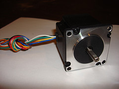
FL57STH51-2808A (axis extending 1 way) and FL57STH51-3008B (axis 2 ways like the picture)

The stepper motors are provided by Bits From Bytes. They come in two variations. Bought three from Bits From Bytes and I got one with the axis through and extending from both ends, and two with the axis extending one side. Their weight is slightly above 0.6 kg (I measured 619 gram).
To make the unipolar stepper a bipolar one, connect these wires together:
- Blue and Red/White
- Green and Black/white
| Name | Color |
| A | Blue/white |
| B | Red |
| C | Green/white |
| D | Black |
Datasheets: FL57STH51-3008B. FL57STH56-2008B
Lin Engineering 5718X-05S

The 5718X-05S has the right specification to drive RepRap from the PIC controllers but we haven't tested it yet. It should work with the Arduino electronics too. It has 200 steps per revolution, so you need to set the controller to half-step it to get the resolution needed. Take care to get the model where the output shaft comes out front and back, not just at the front.