BuildingAStripboardExtruderController
Contents
HOWTO: Building a stripboard Extruder Controller
Introduction
Requirements
Tools and consumables
- A soldering iron and accessories (see Electronics Fabrication Guide).
- Solder
- Electric drill or at least a suitable drill bit
- Some wire for jumpers/links
- Wire strippers
- Small pliers or tweezers
Components
- An 18 pin IC socket
- U1: PIC16F628 microcontroller
- U2: SN754410 quad half H-Bridge
- R1: 200Ω resistor
- R2, R4: 1kΩ
- R3: Chosen to match thermistor and temperature range. See Calculating Thermistor Resistor.
- Connectors. A simple low cost choice is to use header pins and matching sockets. Try to get keyed pins and sockets that prevent you from putting the connector on backwards, because if you do it will most probably destroy the module and possibly other connected modules. Take great care! Alternatively, you can directly solder wires into the board after putting the modules on the machine in which case you don't need any connectors. If you use connectors, you need:
- J1, J2: four pin connector (for comms)
- J5, J6: three pin connector
- J3, J4, J7: two pin connector
- A piece of stripboard with 2.54mm (0.1") spaced continuous track.
Schematic
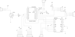
This is the schematic diagram of the circuit you will be building. See reading a schematic to understand the various parts.
Preparing the board
Making the board
Board connections
The connector pins are numbered from the top of the board down, when looking at it as pictured.
- J1 Comms in
- Comms inward (from previous device in ring)
- +12V
- +5V
- Ground
- J2 Comms out
- Comms outward (to next device in ring)
- +12V
- +5V
- Ground
- J3 Heater element
- J4 Thermistor (temperature) sensor
- J5 Motor chopper sensor (optional)
- J6 Out of material sensor (optional)
- J7 DC Motor connector
Variations
Heating element
The heating element is made from nichrome wire. The correct length must be used to prevent drawing too much current for the power supply to handle or too little current to sufficiently heat the material.
First you must select a suitable power output, in general this should be as high as you can afford in your total energy budget. So for example, if your power supply is rated for 12V@10A and the motors and other parts use 6A at peak, then you have 4A to play with for the heater. Ensure you don't choose a current that is too high for the switching transistor deal with. In the schematic above a TIP-31C is used which can handle 3A continuously and 5A for short pulses. For safety, we will restrict ourselves to 3A.
By Ohm's law, V=IR or equivalently R=V/I. So R = 12V / 3A = 4Ω (ohms). So the desired resistance for the nichrome wire is 4Ω.
If you check the specifications for your nichrome wire, it will have a value in ohms/meter at a given temperature. You want the value at around your anticipated working temperature. The resistance drops as the temperature increases. The dropping resistance raises the temperature, which in turn drops the resistance further. Luckily this doesn't go on forever but it leads to fairly inaccurate power consumption if you don't have it right.
Say your wire is rated at 13.4Ω/m at 208C (as mine is). Then to get the desired 4Ω, you need 4Ω / 13.4Ω/m = 0.299m or around 30 centimeters.
This should be connected with heavy gauge wire and wound around the object to heat (which much be non-conductive or electrically insulated).
How to estimate the resistance at your working temperature if your wire specs only have it for a different temperature
Firmware
See the files section at the end for firmware.
A snapshot of the latest source is available for viewing
Troubleshooting
Nothing here yet
If you experience trouble, please share the problems (and resolutions) with us.
See Also
-- Main.SimonMcAuliffe - 03 Feb 2006
