Build Sanguish1.0
Assembly Instructions
Here is a brief pictorial with instructions. You can click on each picture to get a larger view. Component markings are indicated in parenthesis like this (red, red, brown)
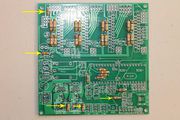
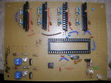
Start with the shortest components. Here are the 2.2k resistors (red yellow red gold). They are used for current limiting on the 12V/24V indicator led's and for weak pull ups on switches. With 2.2k resistors, the LED's should be fine with either 12V or 24V supply for motors and heaters.

Or the jumpers.
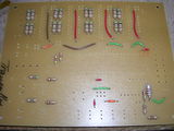
Here's both. The current sense resistors are two 0.5 Ohm resistors per coil for a 2A max current.

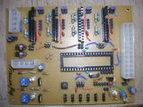
Then the isolation capacitors. These are .1 uf, (104). You'll notice I put a socket in place of the cap in the lower right. This allows you to remove the cap easily to disable auto reset when you are not programming the firmware.
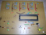
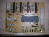
Then the ATMega socket with the notch to the left, the crystal and 22 pf (22J) caps, and the driver frequency caps (101K)

Then pins headers
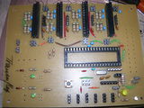
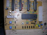
Then sockets if desired for the drivers
Then

Then
Then
Then

Then
Then


