I3 X axis assembly
|
English • العربية • български • català • čeština • Deutsch • Ελληνικά • español • فارسی • français • hrvatski • magyar • italiano • română • 日本語 • 한국어 • lietuvių • Nederlands • norsk • polski • português • русский • Türkçe • українська • 中文(中国大陆) • 中文(台灣) • עברית • azərbaycanca • |
Contents
Assembly instructions
- Bill of materials
- The main panel frame assembly
- Y-axis assembly
- X-axis assembly
- Z-axis assembly
- Connecting X-axiz and Z-axiz
- Power and LCD assembly
- Extruder assembly
- Heated bed assembly
- power switch and end stops assembly
- Control Board assembly and wiring
- Circuit Diagram
Need Parts
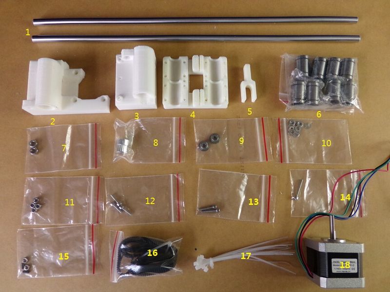
- 1. 2×M8*370 mm Axis
- 2,3,4,5. 4×RP plastic parts
- 6. 8×8UU Bearing
- 7. 2×M5 NUT
- 8. 1×Pulley
- 9. 2×Single Bearing
- 10.8×M3flat gasket
- 11.4×M3 LOCK NUT
- 12.3×M3*12 screw
- 13.2×M3*20 Countersunk head
- 14.1×M3*25 screw
- 15.2×M3 NUT 2×M3*6 blunt end headless screws
- 16.1×Synchronous belt
- 17.8×Tie
- 18.1×NEMA 17
RP Plastic Part
Step 1
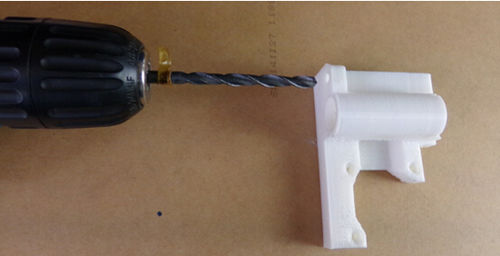
You need the 5mm dill, Set counterclockwise rotation and drill progressively and carefully along the axis.
Step 2
You need 3mm drill.Set counterclockwise rotation and drill progressively and carefully along the axis.
Step 3
You need 8mm drill.Set counterclockwise rotation and drill progressively and carefully along the axis.
X End Idler & X End Motor assembly
Step 1
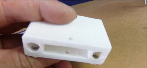
You need the 15 parts.First put the M3 nut in the hole, then tighten the M3*6 blunt end headless screws.
Step 2
You need the 9,10,11,14 parts.Please assemble in accordance with the picture.
Step 3
You need the 7 parts.Please install the M5 nut to plastic parts (red mark).
Step 4
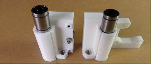
Push two LM8UU linear bearings in the X End Idler and two LM8UU linear bearings in the X End Motor. They can be pushed with hands but you can use a rubber mallet carefully if necessary.
X Carriage
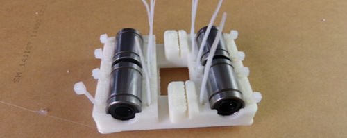
Insert four LM8UU linear bearings on the X Carriage and fix them with eight zip-ties. Make sure to put the « head » of the zip-tie on bearings side.
X-Axis assembly
Step 1
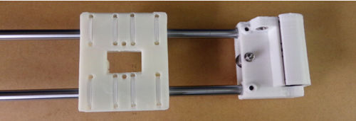
Slide the X Carriage assembly carefully through smooth rods.
Step 2
Push two smooth rods M8x370 mm through the X End Motor. Use a rubber mallet carefully if necessary.
Step 3
Insert the X End Idler assembly and adjust the distance between both Z-axis。
X-axis motor assembly
You need the 8,12,18 parts.Please assemble the X axis motor according to the picture.
