I3 Power and LCD assembly
|
English • العربية • български • català • čeština • Deutsch • Ελληνικά • español • فارسی • français • hrvatski • magyar • italiano • română • 日本語 • 한국어 • lietuvių • Nederlands • norsk • polski • português • русский • Türkçe • українська • 中文(中国大陆) • 中文(台灣) • עברית • azərbaycanca • |
Assembly instructions
- Bill of materials
- The main panel frame assembly
- Y-axis assembly
- X-axis assembly
- Z-axis assembly
- Connecting X-axiz and Z-axiz
- Power and LCD assembly
- Extruder assembly
- Heated bed assembly
- power switch and end stops assembly
- Control Board assembly and wiring
- Circuit Diagram
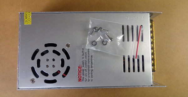
Power supply assembly
Need parts:
- 1×12v 250w supply
- 3×M3*10 screw
- 3×M3 flat gasket
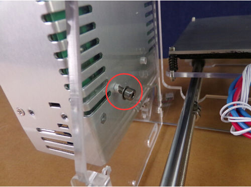
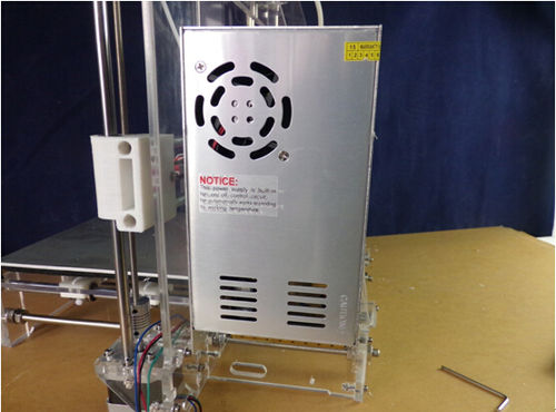
The following two screws in the power supply , one on top of the screws and then tighten.
LCD assembly
Need parts:
- 1×LCD
- 4×M3*25 screw
- 4×M3 nut
- 4×M3 lock nut
- 8×M3 flat gasket
- 4×plastic gasket
Step 1
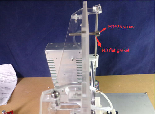
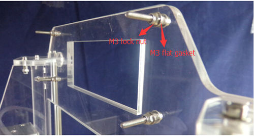
M3 * 25 screw and a M3 flat gasket insert acrylic sheet.
Step 2
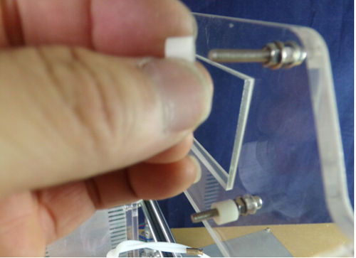
Plus a flat gasket and use M3 lock nut tightening. then Coupled with a plastic pad.
Step 3
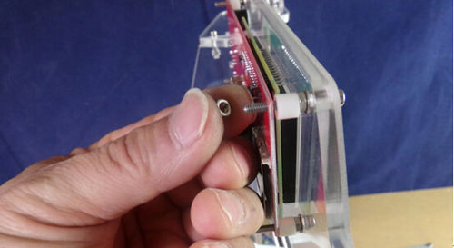
Inserted 4×M3*25 screw into four holes of LCD, and then tighten with M3 nuts.
