Generation 3 Electronics/Tech Zone Remix/How to
Release status: unknown

| Description | "How to" Manual for the Techzone Remix Electronics Kit
|
| License | |
| Author | |
| Contributors | |
| Based-on | |
| Categories | |
| CAD Models | |
| External Link |
!!! I'm writing this as a manual to the "TechZone Electronics Kit"... Please feel free to edit any errors or discrepancies... feel free to add to this page...
This page (as of now) is purposely not linked inside the wiki... (keeping it on the D.L. ...) since its a work in progress i have lots of notes everywhere... sorry...however if someone should need some help? feel free point them here... because you never know if current unfinished work might help them! (so I'm currently trying to keep this off the public channels at least for a few more days maybe a week... invitation only for now... those who NEED it and those invited... so invite everybody you think can help!!! even the little things... progress is progress!
(the ground-work needs to be laid-out first and then pics need to be uploaded...) so here we go... on with the ground-work!!!
Contents
Before We Begin... Things You Should Know...
First: (Kiymberly, Here's your cue!!! this parts all YOU! jump im here! we need an intro-draft... I'll arrange it later)
FAQ's
- The TechZone electronics kit comes with Makerbot firmware by default! This means that it already has a boot-loader installed. Also this means that the ReprepMendel Firmware needs to be uploaded to the Motherboard and Extruder-board to re-configure them PROPERLY before you start connecting/testing them... Note you MUST be able to upload firmware or you will be stuck! the firmware is where the software and settings ___duh___duh gone cross eyed... need break.... 10:14pm (-6:00)
- For more FAQ's see the FAQ page I setup...Generation 3 Electronics/Tech Zone Remix/How to/FAQ Page
About this Page: (A note from the Author.)
In this page I will attempt to give you an idea about how to go about wiring your Mendel. However you must realize that since these boards are a new development that there is no "official" way of wiring them. So the idea here is for us to kinda like, build "our own" (the community's) DIY manual.
- All of the images used are shrunk down from their original size... Just click on an image to see it in High-Resolution... A few inages might be a little fuzzy...(I'll try to update them soon.)
- All references to wiring connections are placed under the heading "Miking the connection..."
The USB/TTL Board
The TechZone Remix is considerably smaller. This circuit has the least modification, since there were no extraneous pins or connectors.
We did change the screw down terminal used for the temp connection to a 2 pin .1" jumper terminal.
We also used higher amp mosfets in a Dpak configuration (almost all standard mosfets in a Dpak will work on this board, so you can select values which are correct for your use, if you are building your own.
We added an additional footprint for the processor (like on the Mainboard, and for the same reasons) and we added a footprint to the full bridge control chip(s). We are currently using the additional bridge motor control footprint for testing... so, more to come on that in a few weeks we hope.

- To begin we need to clearly mark the ground pin of the serial connection... (here we need a pic of the board pointing out the ground pin and marking it with a sharpie...)
- Drivers
- I have tried 3 Different sets of (Windows) "FTDI USB" drivers and all seem to work fine... The drivers I tried are as follows:
- 1. The drivers that come bundled with replecatorG-0014
- 2. The drivers that come bundled with anduino 18
- 3. The drivers off the IC Manufacture's website
- I have tried 3 Different sets of (Windows) "FTDI USB" drivers and all seem to work fine... The drivers I tried are as follows:
The Main Motherboard
The TechZone Remix is drastically reduced in size, The SD card slot has been replaced with a microSD card slot, which is on the back side to further reduce size of the board. extra pins on the I2c communications have been removed (which results in the same number of pins and connections as what you end up with when you modify the Generation 3 Electronics as per the directions here [1][2].
We have also added an additional footprint for the processor, to allow the use of the QFN pack instead of the TQFP (it is much more difficult to solder, but, it is much easier to find and purchase)(here we need a pic of the mother board labeling the pins... by needed connections..(connections that apply to reprap Mendel)
Connecting The Motherboard to the USB/TTL Board to Load Firmware:
Making the Connection:
- In this section I explain how to punch-down a IDC connector with a very narrow (width) flat tip screwdriver.
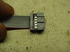
- Making Your Cables (Insulation Displacement Connectors)
- The first thing you want to do is separate the tip of the ribbon into short strands so it can be inserted into the cable (pic)
- Next using a small precision screwdriver you want to lightly tap the each conductor as to get it started.. This is to hold the ribbon while you do the next step...
- Next take an even narrower screwdriver and tap the wires down the rest of the way. Being careful not to stab through the conductor!
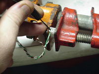 Image a lil fuzzy sorry (needs to be updated..)
- The Jumper Technique...
- This is a solution I came up with to upload the needed firmware for setup, bench testing and for troubleshooting cable problems... As you can see from the pictures below I used reversible jumpers that I pulled from old computer parts.
- Note if you use this technique on the extruder board, you will need to flip the USB/TTY board Top-Side-Down... due to the fact that the ground pin on the extruder board is on the opposite side!
- This is a solution I came up with to upload the needed firmware for setup, bench testing and for troubleshooting cable problems... As you can see from the pictures below I used reversible jumpers that I pulled from old computer parts.
- Making Your Cables (Insulation Displacement Connectors)


Uploading Firmware
- Once you have connected your USB/TTL interface to your motherboard you can upload the Motherboard 5Gfirmware for the first-time!!!
- The processes of uploading firmware are the same as the Makerbot set... The only difference is that the jumper to upload firmware is already installed... Microcontroller_firmware_installation
The Extruder Board
Again, the TechZone Remix is considerably smaller. This circuit has the least modification, since there were no extraneous pins or connectors.
We did change the screw down terminal used for the temp connection to a 2 pin .1" jumper terminal.
We also used higher amp mosfets in a Dpak configuration (almost all standard mosfets in a Dpak will work on this board, so you can select values which are correct for your use, if you are building your own.
We added an additional footprint for the processor (like on the Mainboard, and for the same reasons) and we added a footprint to the full bridge control chip(s). We are currently using the additional bridge motor control footprint for testing... so, more to come on that in a few weeks we hope.
- pot warning
- polarity warning
- serial polarity warning
Uploading Firmware
- Jumpers Again? Yep
- TEXT
- (PIC)
- Note if you use this technique on the extruder board, you will need to flip the USB/TTY board up-side-down... due to the fact that the ground pin on the extruder board is on the opposite side!
- TEXT
- Reset trick
Making the Connection
- A note on Wire Preparation: Its always a good idea to tin (tin: to put solder on)your wires! it helps keep the strands of the wires together (to prevent a short) and it also help keep the wires from breaking/getting pulled out.. (It gives the scerew something to bite down on..)


- 12 Volt power
- Heater connection (Pic)
- Cooling Connection (PIC)
- Thermistor Connection (PIC)
- Stepper Motor Connection (pic)
- Rs485 Connection (pic)
- Step/Direction Connection (pic)
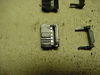
- CD-Rom Audio Cable Technique:This is one solution against Cable Noise. (RMI or magnetic Interference..) This is one of the things i did to solve a problem where my extruder-stepper was going crazy.[3]
- What i did was i used a cd-rom analog audio cable for my i2c signal... using a small screw driver, i was able to remove the pins from the connectors and re-arranged them to my needs leaving the ground pins loose so i could connect them to the ground pins on the boards...
- What i did was i used a cd-rom analog audio cable for my i2c signal... using a small screw driver, i was able to remove the pins from the connectors and re-arranged them to my needs leaving the ground pins loose so i could connect them to the ground pins on the boards...


Stepper Controller Board
I don't think we made any chages here, except for the size, and pre-changing the connections as per the RepRap configurations (here)[4]
- pot warnings
Making the Connection
- Connecting Your Stepper Motor
- Connecting power 12 Volt power
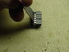
- Here are a few ways to make a 10 pin cable...
- Making a 10pin IDC Cable.. Here i show how to identify Pin#1 on the 10pin connector.
- Some things on this topic have already been covered...hereElectronic_wiring#Stepper_wiring
- Make 2 out of an IDE cable (PICS)
- Taking a IDE cable from a computer, I was able to Make 2 10pin ribbon cables using a hack saw (pic)...
- by cutting the connector almost all the way through (PIC) with the saw I was able to achieve a clean break through the last bit of plastic close to the cable. (PIC)
- Making a 10pin IDC Cable.. Here i show how to identify Pin#1 on the 10pin connector.
- Make a breakout to use a Stepper Board to drive your Stepper Extruder Motor... (optional Stepper board needed)


Coming soon!
The Opto End-stop
This board is not based upon the OptoEndstop_2.1, but it uses the same opto-sensor... it may still be a derivative of the OptoEndstop_2.1 board.
- It behaves differently, the LED lights up when there is NOT an object in the sensor, rather than when there IS an object in the sensor
- Polarity Warning
Make the connection...
- Jumpers to the rescue!
- Making Your Cables (Insulation Displacement Connectors)
- The first thing you want to do is separate the tip of the ribbon into short strands so it can be inserted into the cable (pic)
- Next using a small precision screwdriver you want to lightly tap the each conductor as to get it started.. This is to hold the ribbon while you do the next step...
- Next take an even narrower screwdriver and tap the wires down the rest of the way. Being careful not to stab through the conductor!
- Image a lil fuzzy sorry (needs to be updated..)