Heater Block For Glass Nozzle
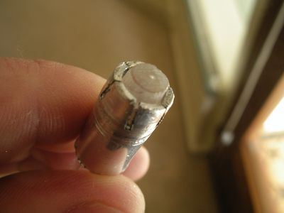
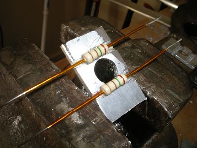
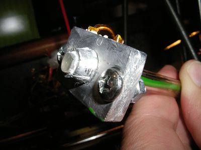
Greg Frost has never liked dealing with nichrome. He agrees with nophead and doesn't know why resistor heater blocks are not yet adopted as the official hotend. He also wanted to experiment with glass nozzles. A problem with glass nozzles is the poor conductivity of glass means that you want to deliver heat near the end of the nozzle. When thinking about how this could be done, and rifling through the stuff he had on hand, he found an aluminium tube with 10mm OD and approx 8 mm ID (which matches RocketScientist's glass nozzle OD. A quick ream with an 8mm hand drill, 3 cuts with a hacksaw and a bit of judicial squeezing with some pliers yields this:
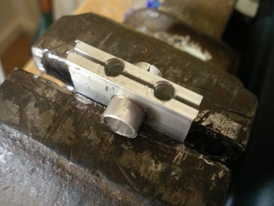
He cut 2 pieces of 20mm wide aluminium strip and drilled a 10mm hole through both of them that fitted the sleeve snugly.
He then drilled 2 4.8mm holes as close to the sleeve as possible. These holes only go about 3/4 of the way through. The hole is drilled the rest of the way with a 2.5mm drill. This gives room for the resistor lead but prevents the resistor from going all the way through (and gives a bit of extra strength to the strip which otherwise would be quite thin all the way across where the hole was drilled. Using a hand drill, and because Greg is a bit of a hack, one of the holes actually sliced into the sleeve, but this is actually OK and when the resistor is installed, it will prevent the sleeve from slipping through (or the strips from slipping down).
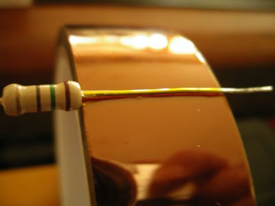
Then he insulated the resistor leads by wrapping Kapton tape around them. A handy hint for doing this neatly is to peel a bit off the reel and then slice it off neatly with some scissors. Then put the resistor lead under the small piece of tape sticking up and press it onto the lead. Then rotate the resistor to tightly wind as much Kapton onto it as you like.
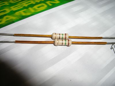
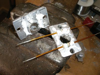
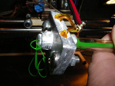
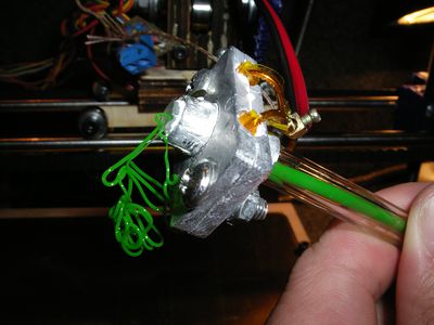
In the end you end up with very neat insulated leads as shown below. Im using 2 15 ohm resistors which will be placed in parallel to give about 7.5 ohms.
This shows how the resistors sit in the holes that have been drilled for them.
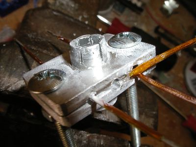
This shows the pieces about to be assembled. Notice the additional holes for M4 bolts to clamp the alu strips together.
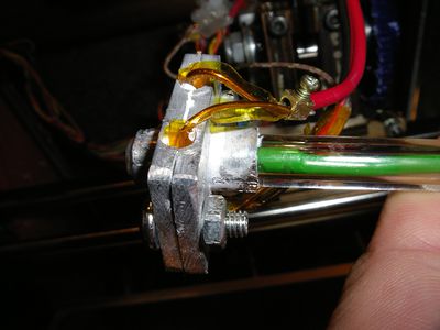
To measure the temperature he sandwiched a thermocouple between the two alu strips and then clamped it by tightening the clamping bolts. He found that after he had clamped it, the resistors had shorted on the block (the paint cracked off the ends). He fixed this be disassembling and wrapping a single layer of kapton around the body of the resistor too. You may want to do this right of the bat.
