组装X轴
       介绍|搭建框架|组装Y轴|组装X轴|组装Z轴|组装热床|挤出机组装|热端组装|电源|布线|调试|打印
                                多颜色/多材料|维护|故障排除|改进
Contents
目标
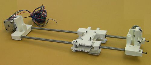
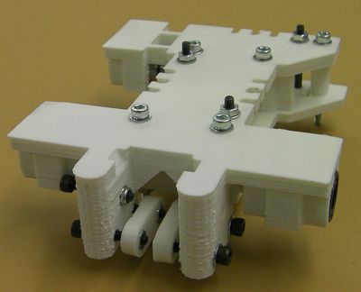
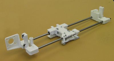
在完成这一步以后,你的X轴将像下图一样:
(在这张图中,以及这一步中的其他图,你可能会看到热屏蔽纸板已经组装上X托架下。但事实上安装热屏蔽纸板是在组装Z轴这一步中做的,也就是在下一步中做的。)
工具
你将会使用以下工具
- M3 内六角扳手
- M3 固定螺丝用的六角扳手(set screw allen key)
- M3 扳手
- 尖嘴钳
- 镊子
- M8 扳手
第一步:x托架安装
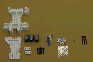
| |
| 物品 | 数量 |
| 打印的X托架盖 | 1 |
| 打印的X托架板(底座) | 1 |
| 打印的X皮带夹 | 2 |
| LM8UU 轴承 | 3 |
| M3x20mm 螺丝 | 5 |
| M3x35mm 螺丝 | 5 |
| M3x30mm 六角螺丝 | 3 |
| M3 尼龙自锁螺母 | 1 |
| M3 螺母 | 22 |
| M3 垫圈 | 27 |
托架
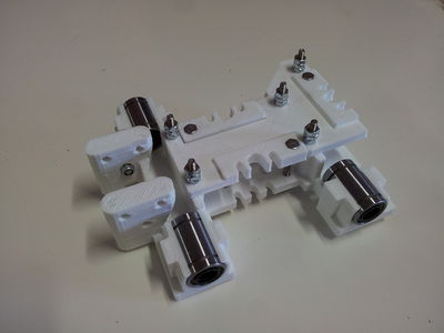
将托架朝上,放置LM8UU轴承在托架的凹槽中:
不要试图从上往下放置轴承 ,这将使托架碎裂。轴承应紧密贴合。但是如果它们有一些松动,使用聚酰亚胺胶带(Kapton胶带)在外侧包裹两到三圈。使它平整,没有任何皱纹和气泡。
可选的(在标准的RepRap Mendel套件中并不包含这些): 安装4个16毫米M3螺帽,4个垫圈和螺母(不包含上表中)在托架上,如图所示。这些现在不需要,但是在将来加强时需要。如果你现在这么做,以后你将不再需要把托架拆下来。
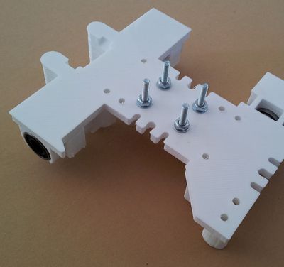
安装六角螺丝在托加盖的凹槽中。你可能发现在托加盖的另一侧放上一个螺母和垫圈(随后移除),将使得放置六角螺丝到凹槽中变得容易。确保螺丝的六角和六角洞完全对齐在你开始用力以前。
使用35毫米螺丝、螺母和垫圈来将托加盖固定在托架上。使螺丝末端露出一下,如上图所示。安装2个额外的螺母和2个垫圈在每个螺丝上(一共3个)。这将在后面安装放置隔热板时使用。把另外两个螺母(一共3个)以及两个垫圈(每一对螺母之间两个垫圈)放置在螺丝上。这个是为了后面放置热屏蔽而使用的。
放置螺母和垫圈在六角螺丝的末端。
不要旋紧它们,这些螺丝允许你调节托架中多个挤出机的相对高度。
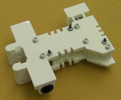
使用螺丝,螺母和垫圈安装皮带夹。
首先,将螺母放入凹槽中。你可以通过放置一个点钱在螺丝下。确保你旋紧螺丝时,螺母的六角和六角洞完全对正。
夹子上的皮带凹槽对着垂直的柱子。
使用尼龙螺母安装张紧螺丝,如图所示:
Step 2: Main X axis assembly
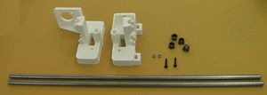
| |
| Item | Quantity |
| Printed X end (motor) | 1 |
| Printed X end (idler) | 1 |
| 428mm smooth 8mm rods (X) | 2 |
| 8mm IGUS bearings | 4 |
| M3 nylock nuts | 2 |
| M3x16mm screws | 2 |
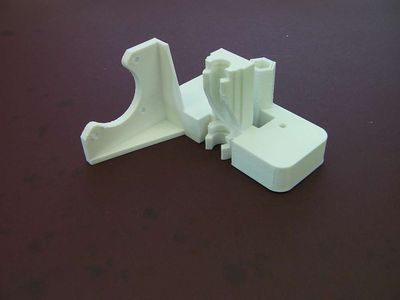
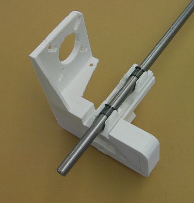
Please note that there is an improvement to the design of the X motor end. It looks like this:
Start by fitting the IGUS bearing inserts to both ends:
You can curl them up so their ends overlap to insert them. Be careful.
Check their internal diameter by running one of the 8mm rods down them. If the rod is too tight (don't force it) put a 9.5mm drill bit shank in a vice, take the bearing inserts out, and slide the printed part over the drill to clean out the hole. Again be careful - you don't want to remove too much material and make a sloppy fit.
Repeat this process until the rod just fits and slides smoothly. It should not wobble from side to side.
With the tweezers fit the nylock nuts into their recesses in the idler end:
Pull the nylock nuts into their recesses with a screw if needs be.
Screw the two screws in by just three or four turns. Slide the smooth rods in so that they abut the screws and nuts.
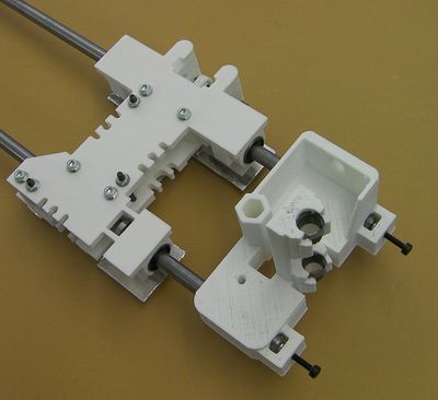
Put the X carriage on the rods. Make sure to get it the way round shown in the picture.
Insert the rods into bearings while watching the opposite end of each bearing to make sure none of its balls get pushed out of their tracks. If they do, they can be reseated by pressing them back into the track with the tip of a chopstick. As a precaution, cover the area under your work with a tissue to catch any balls that might fall out.
Put the motor end printed part on the other ends of the rods. Make sure they slide right up to the closed ends of their holes:
Step 3: Fit the X motor
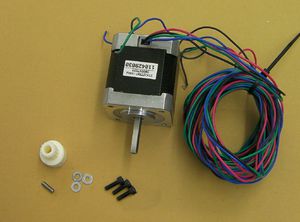
| |
| Item | Quantity |
| NEMA 17 motor | 1 |
| M3x10mm screws | 3 |
| M3 washers | 3 |
| Toothed belt pulley | 1 |
| M3 x 10mm set screw | 1 |
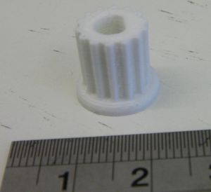
Later versions of Mendel have printed toothed-belt pulleys like this:
These simply push-fit onto the motor shaft - see below.
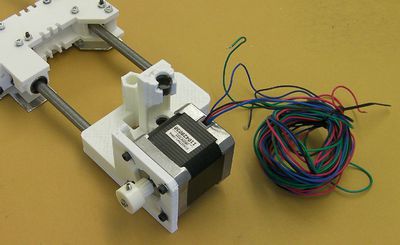
Use the screws and washers to mount the motor:
If you have a moulded pulley, screw the set screw into the toothed-belt pulley. Take care not to cross the threads - the plastic is not hard. Screw it in far enough to project into the hole down the middle, then back it off so it is no longer projecting. Blow any displaced pieces of plastic from the central hole. Put the pulley on the motor shaft with its hub outermost, as shown. Use the toothed belt to get it roughly the right distance along the shaft. Align the set screw with the flat on the shaft, and tighten it. Do not over tighten it - the pulley has an internal embedded nut, and over tightening will cause this to fracture the pulley.
If you have a printed pulley push it onto the shaft. It should be a tight fit, and you may have to tap it into place. Use a soft hammer, or a wood block. If you place an M8 nut against the pulley, you can tap the nut to place the pulley. Support the motor shaft, not the motor body, from the other end as you tap. You can secure it with a drop of superglue if you like (make sure the shaft is completely free of grease). Take care that no glue gets near the shaft's entry to the motor.
Step 4: The X belt idler
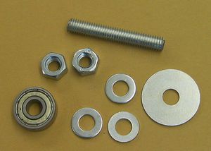
| |
| Item | Quantity |
| 35mm M8 threaded rod | 1 |
| M8 nuts | 2 |
| M8 mudguard washer | 1 |
| 8mm bearing | 1 |
| M8 washers | 3 |
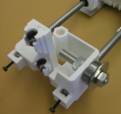
Fit the idler:
From the right the sequence goes:
- Nut
- Mudguard washer
- Washer
- Bearing
- Washer
- Printed idler end
- Washer
- Nut
Next stage
声明
本资料由zlz首先开始志愿翻译,相关pdf文件可点击这里下载。
由于各种原因,难免存在错误,若有描述不清楚的地方,可查看英文原版,若发现问题,还望见谅并请直接改正。
