组装Z轴
       介绍|搭建框架|组装Y轴|组装X轴|组装Z轴|组装热床|挤出机组装|热端组装|电源|布线|调试|打印
                                多颜色/多材料|维护|故障排除|改进
Contents
目标
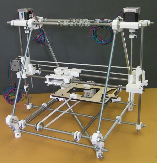
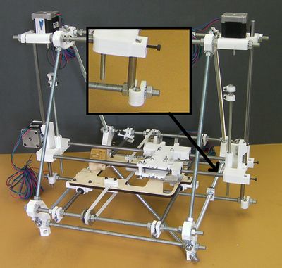
在完成这一步以后,你的reprap将会像这个一样
工具
你将需要以下工具:
- M3 内六角扳手
- M3 扳手
- 精准螺丝刀(小螺丝刀)
- M2.5 扳手
- M8 扳手
第一步:Z轴螺杆
| |
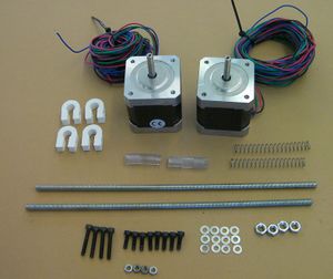
| 物品 | 数量 |
| NEMA 17 电机 | 2 |
| 25 mm 弹簧* | 2 |
| 215mm M5 螺杆 | 2 |
| M5 螺母 | 4 |
| 30mm x 5mm 聚乙烯管(id poly tube) | 2 |
| 打印的U形夹 | 4 |
| M3 x 20mm 螺丝 | 4 |
| M3 螺母 | 4 |
| M3 x 10mm 螺丝 | 8 |
| M3 垫圈 | 12 |
*图中所显示的弹簧太长,你应该使用25mm长的。
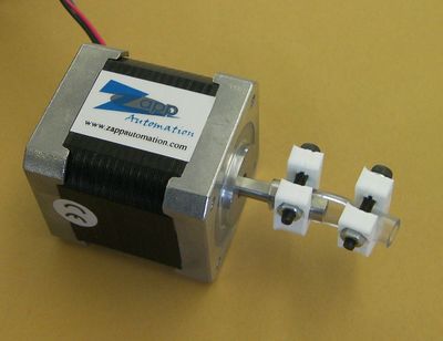
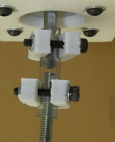
首先,使用U形夹把塑料管安装在电机上。使得每个夹子的间距根据电机轴上对齐:
把两个夹子都安装好,但是不要旋紧它们。将塑料管套入电机轴,套入的长度大约为塑料管的一般。
然后使用短螺丝和垫圈在框架顶端安装Z电机。
使导线指向机器中心。
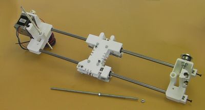
接着在X轴上安装M5螺纹杆,M5螺母和弹簧:
在连接杆上安装螺母,并且确保它和X轴末端的六角凹槽相吻合。他应该是正好的,但是可以上下自由移动。如果六角凹槽里面有很紧的地方,使用螺丝刀刀片去除掉。
现在安装螺母和杆。沿着杆,将螺母放在中间,然后放上弹簧,并压下弹簧直到六角凹槽的顶部。
压下弹簧,然后将另一个螺母放在螺杆的底部。当弹簧释放的时候,它应该弹起那个螺母到六角凹槽的底部,其余的限制在10毫米以内。调节它们,使得顶部的螺母和顶部的凹槽紧贴。
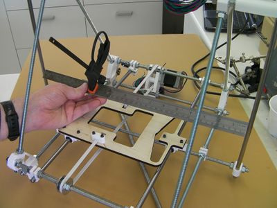
检查Z棒是平行的:
一个简单的方法是:两把尺拼接在一下,如图所示,检查底部,中间,顶部的距离。通过旋紧、松弛M8螺母调节,夹住Z杆的底部。使你的调节是对称的,你在左边调节多少,那么你在右边也需要调节多少。 你可以用笔标记螺母,这将让你直观的看到你移动了多少。
Step 2: Fit the X axis
(The picture is wrong: the plastic tubes and their U clamps should be on the motors at this stage, not the M5 rods.)
Slacken the nuts on the Z motor mounts that retain the Z rods. Slacken the outer nuts on the U clips at the base of the Z rods. Make sure that the inner nuts do not move - then when you re-tighten things everything will go back to the same place.
Slide the Z rods upwards by about half their length. You may need to tighten the top nuts by hand to stop them falling again.
Move the Y frog to the middle of the machine.
Put the X axis on the Y frog. Pack the X axis up with a scrap of wood or similar to get it level and stable.
Push the left-hand Z rod down through the IGUS bearing inserts by the X motor and on down through the U clip at the bottom. Again, take care not to move the inner nut.
Tighten the outer nut on the Z rod, and also tighten the nut at the top on the Z motor mount.
Push the right-hand Z rod down through the X carriage and stop just above its U clip.
The Z rod will be on the inside of the U clip. That is to say, the X axis is (deliberately) too short. (See the inset image.)
With an M3 Allen key, tighten the screws in their nylock nuts on the ends of the X rods. The bottom of the Z rod will move outwards. Adjust it so that it just lines up with the hole down the U clip, then push it on down through the U clip.
Tighten the nuts on the Z motor mount and the outer nut on the bottom U clip to hold the right-hand Z rod firmly.
Finally for this step use a rectangular object to support the X carriage on the Y Frog. Then screw the ends of the M5 rods into the plastic tubes on the motors.
Have gaps of about 2mm to 3mm between the tops of the M5 rods and the bottoms of the motor shafts. (You can see this because the poly tube is transparent.)
Tighten the U clamps on the motor shafts and the M5 rods. Remember to have the flats on the motor shafts aligned with the gaps in the clamps.
Turn the Z motors by hand to get the X axis level. To check this, move the Y frog and the X carriage out of the way, and use digital callipers to measure the gaps between the Y rods and the X rods. These gaps should be the same left and right.
Step 3: The adjustable Z endstop
Note that the X and Y axis stop brackets are identical. The Z stop bracket holder has a longer leg; that is the one you want.
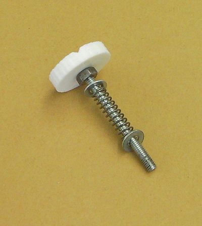
Start by using the 35mm hex-head screw together with nuts, washers and the spring to assemble the adjuster:
Then use an M3 nut underneath to fit the adjuster to the motor end of the X carriage:
Pull the nut into its hexagonal recess under the carriage. Make sure the two hexagons line up.
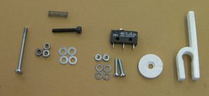
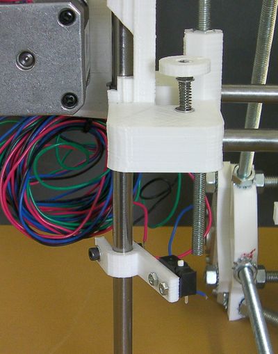
Assemble the switch together with the "h" shaped piece using the M2.5 screws, washers and nuts as shown and fit it to the smooth Z rod.
The remaining M3 parts close the h-clamp. Don't do it too tight - it needs to be firm and unmoving, that is all.
The switch button should line up with the end of the adjustment screw.
Step 4: The X belt and endstop
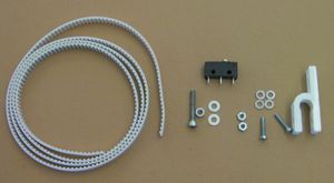
| |
| Item | Quantity |
| Printed XY-stop bracket | 1 |
| M2.5x16mm screws | 2 |
| M2.5 washers | 4 |
| M2.5 nuts | 2 |
| microswitch | 1 |
| M3 x 20mm screws | 1 |
| M3 nuts | 1 |
| M3 washers | 2 |
| toothed belt | left over from Y axis |
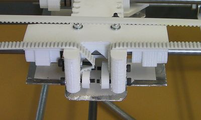
Loop the belt round the X motor pulley, over the X idler bearing at the other end, and attach the ends of the belt to the carriage as shown:
The belt will be a little too long. Pull it so there's no slack, check that the belt teeth are located in the dents for them in the clamps, tighten the clamps, and remove any excess with sidecutters. You want the ends of the belt projecting about 2mm below the carriage.
Use the belt adjusting screw to tension the belt. It must be under just enough tension to remove any slack. While testing for slack, any rotation of the motor shaft, no matter how small, should result in a corresponding motion of the carriage, especially on reversal. There should be no visible deformation of the belt near its attachment points when the motion is reversed. On the other hand, the tension must not be so high as to distort anything. Get it just tight enough that there is no slack or play in anything; no further.
Swing the X carriage several times from one end to another and also move it back and forth in shorter strokes around several different points in range (e.g., 1/4, 1/2, 3/4), or just pick points randomly. Watch how the belt tracks the idler pulley and the motor gear. If it crawls off to one side, check that:
- The top side of the belt and its attachment points are in the same plane
- The motor and the idler axes are parallel
- The belt is properly tensioned
Fixes to the belt wandering can include repositioning the belt guides in the carriage top (cutting deeper ones in the right places with a utility knife), shimming the idler bolt and/or the motor with scraps of folded paper (on the motor end, washers can be added between the motor and the mounting bracket), and adjusting the tension. Up to a point, a higher tension may result in a more stable belt, but care must be taken to avoid warping the rig.
A successful alignment should result in a small amount of crawl (less than a millimetre) near the edge of the idler, possibly with a small overhang. Because a flat belt on a straight cylindrical pulley is an unstable system, it will either be attracted to the edge (success), or crawl off to touch the bracket or the guard (failure). The bevelled edge of the idler acts as a poor man's crowned pulley, so it is normal for the belt to stabilise at the edge.
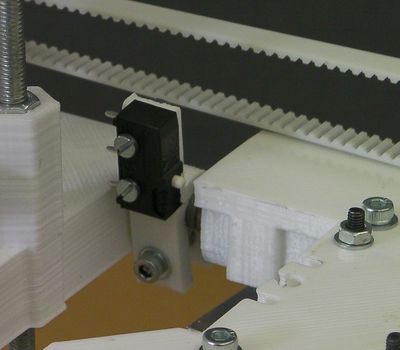
Fit the X endstop as shown. It goes on the back of the X carriage at the motor end:
Check that the X carriage hits the switch, but don't do it up tight - you will have to take it off again to wire it up.
Step 5: X carriage heatshield
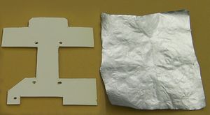
| |
| Item | Quantity |
| Cardboard heatshield* | 1 |
| Aluminium cooking foil* | 110mm x 135mm |
*Kits supplied from RepRapPro Ltd have the heatshield pre-cut from aluminised card. For those you can skip the next DIY section.
DIY Heatshield
Start by gluing the aluminium foil to the cardboard heatshield. The aluminium needs to go on the underside of the cardboard when the cardboard is the way up shown in the picture above.
Virtually any glue will do, but aerosol spray glue is easiest. Spray the foil, then drop the cardboard onto it and press it down against a flat surface.
Trim the foil about 5mm out from the edge of the cardboard and fold it over and stick it around the edge on the back. You can make a neat job if you make rectangular cuts of the foil by convex corners, and 45 degree angled cuts in to concave ones.
Let the glue set.
Install Heatshield
Fit the heat-shield under the X carriage, with the aluminium face pointing downwards. Sandwich it between the washers between the nuts that you fitted earlier for this purpose. Fit it as low as you can, with the bottom nuts at the end of their travel.
