Arduino Mega Pololu Shield
Release status: Working

| Description | A RepRap etch resist printable circuit board that fits on the Arduino MEGA and holds interchangeable stepper driver carriers and the rest of RepRap's electronics.
Arduino MEGA based modular RepRap electronics.
|
| License | |
| Author | |
| Contributors | |
| Based-on | |
| Categories | |
| CAD Models | |
| External Link |
Contents
Summary
Instructions for version 1.3 are being created at RAMPS1.3
RepRap Arduino Mega Pololu Shield, or RAMPS for short. It is designed to fit the entire electronics needed for a RepRap in one small package for low cost. RAMPS interfaces an Arduino MEGA with the powerful Arduino MEGA platform and has plenty room for expansion. The modular design includes plug in stepper drivers and extruder control electronics on an Arduino MEGA shield for easy service, part replacement, upgrade-ability and expansion. Additionally as long as the main RAMPS board is kept to the top of the stack a number of Arduino expansion boards can be added to the system.
As of version 1.3 in order to fit more stuff RAMPS is no longer designed for easy circuit home etching. If you want to etch your own PCB either get version 1.25 or Generation7. Version 1.25 and earlier are "1.5 layer" designed boards (i.e. it's double sided board, but one of layers can easily be replaced with wire-jumpers) that is printable on your RepRap with the etch resist pen method, or home fabbed with toner transfer.
This board is mostly based on Adrian's Pololu_Electronics and work by Tonok. Copper etch resists methods suggested by Vik. Also inspired by Vik's work with EasyDrivers. circuit design based mostly on Adrian's Pololu_Electronics Joaz at RepRapSource.com supplied initial pin definitions and many design improvements. Much inspiration, suggestions, and ideas from Prusajr, Kliment, Maxbots, Rick, and many others in the RepRap community.
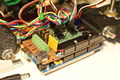
Mendel printed RAMPS wired to Mendel.
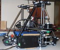
Mendel with RAMPS in enclosure mounted.
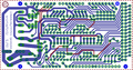
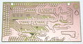
screen capture of 2-sided RAMPS layout
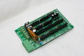
commercially fabbed 2-sided RAMPS wired to Mendel
RAMPS1.3


Features
- It has provisions for the cartesian robot and extruder.
- Expandable to control other accessories.
- 3 mosfets for heater / fan outputs and 2 thermistor circuits.
- Fits 4 Pololu A4983 stepper drivers
- Pololu boards are on pin header sockets so they can be replaced easily or removed for use in future designs.
- The pin headers for the stepper motor outputs are placed on top of the Pololu boards saving routing them on the main shield.
- I2C and SPI pins left available for future expansion.
- All the Mosfets are hooked into PWM pins for versatility.
- Servo style connectors are used to connect to the endstops, motors, and leds. These connectors are gold plated, rated for 3A, very compact, and globally available.
<videoflash type="youtube">0k_KArg_sgA</videoflash>
Safety Tip
Once you start putting electricity into your RepRap - even at just 12 volts - you have to take basic, common sense precautions to avoid fires. Just in case these fail, test your workshop smoke detector. Got no smoke detector? Get one!
Support
The primary channel for RAMPS support is the RAMPS Forum
Safety Tip
Once you start putting electricity into your RepRap - even at just 12 volts - you have to take basic, common sense precautions to avoid fires. Just in case these fail, test your workshop smoke detector. Got no smoke detector? Get one!
Development
If you're reading this, you're probably a reprap-developer. We'd be honored if you join the reprap-dev mailing list and help make RAMPS better. :D
Build and Use
See RAMPS1.3 and RAMPS 1.2 (older versions are currently split between the 1.2 page and viewing the old history of
Custom Versions
Ingredients
Schematic
Current schematic shown. For older versions click the image. Click again for full image.

Source
| FILE ID# | TYPE | DESCRIPTION | DOWNLOAD |
|---|---|---|---|
| File:ArduinoMegaPololuShield.zip | Eagle Files | These are the files you need to make the board.(Use the File: link to the left to access older versions of the file.) | media:ArduinoMegaPololuShield.zip |
| File:RepRapjr.lbr | Eagle Libraries | The components used in this board are here. see Eagle_Library | media:RepRapjr.lbr |
Grogyans
Will have locking connectors for the motors. Uses the MAX6675 thermocouple sensor, which essentially replaces the AD595. Less vias, which should also increase building time. Bottom only, to enable the possibility of a RepRap or toner transfer method to fabricate the board. Moved the power LED to the front for easy identification. Providing the user has a proto-shield for Mega, there is plenty of pins left for them to play with. By using another tiered board, will alow the possibility of more extruders and LCD all of which can communicate over the I2C protocol.
All work done so far is two days in the New Zealand summer.
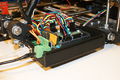
Electronics Enclosure
This is an enclosure for the RAMPS version 1.2 it will not work with other versions. Feel free to join the race to get an awesome case for v1.3
It has a mount built in for a 40mm fan and LED. Shown printed in PLA. There is talk that it is currently unprintable in ABS due to warping.
It uses 2.8mm holes to for the 3x16mm cap screws that mount it and the Arduino stack inside. These holes print a little undersized with my configurations and hold a 3mm screw pretty good.
The files say v1.1, but the enclosure is also compatible with v1.2
| IMAGE | FILE ID# | TYPE | DESCRIPTION | DOWNLOAD |
|---|---|---|---|---|

|
File:RAMPS1-1case.zip | STL | All the stl files for the v1.1 enclosure in a zip | media:RAMPS1-1case.zip |

|
File:RAMPS ADfiles.zip | Alibre Design Files | These are the original design files. | media:RAMPS ADfiles.zip |

|
RAMPS-Case-Top3 | STL | The lid for the enclosure. Has mount for 40mm fan. Chose the one that fits your vs of the board with or without UltiMachine logo. | media:RAMPS-Case-Top3v1-1.stl
media:RAMPS-Case-Top3v1-1noUlogo.stl media:RAMPS-Case-Top3v1-0.stl |

|
RAMPS-Case-Base3 | STL | The bottom half of the enclosure. Chose the one matching your vs. | media:RAMPS-Case-Base3v1-1.stl |

|
File:RampsWindow.stl | STL | Covers teardrop holes and serves as reset button lever | media:RampsWindow.stl |

|
File:RampsResetButton.stl | STL | Attached through window with 3mm filament. | media:RampsResetButton.stl |

|
File:RampsMountSpacer.stl | STL | Spacer to raise enclosure up above the bottom nut outside the frame vertex. | media:RampsMountSpacer.stl |
ALTERNATE ENCLOSURE
The previous enclosure isn't printable on a Makerbot. This one is Modular RAMPS Case on Thingiverse
Basically, it's a series of interlocking tiles with a few functional modifications. It's printable in ABS, and on a smaller build surface, but you do have to glue the pieces together and drill a few holes.
The openscad script is available so you can modify the files if you want.
Showcase
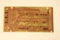
printed on a RepRap Mendel with the etch resist method Using_cad.py
attempt at printing labels with sharpie
Two-sided PCB Built v1.0
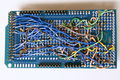
messy back of the first prototype of RAMPS -- built on a generic megaproto shield with point to point wiring, rather than a custom RAMPS PCB
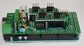
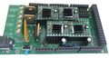
RAMPS with standard pin headers

Add your pics here!!!


Change Log
- 1.3 May 13, 2011
- Added 5th stepper driver socket
- Added 3rd thermistor circuit
- Added Heated eed circuit w/ 11A PTC fuse, changed to 4 position pluggable input jack to accomodate additional current
- Increased board size to 4"x2.32"
- Pin order on heater outputs changed
- Increased spacing increased to accomodate diff connectors
- Added connectors for optional 2 motors on Z driver
- Added connector for PS control
- Improved expansion connector layout
- Moved LED towards coner and added resistor to LED circuit
- No longer optimized for home etching :(
- License changed to GPL v3 or newer
- v1.2 January 04, 2011
- Added 0.1" motor connector to RAMPS for each driver (motors no longer have to be connected on top of stepper drivers)
- Added breakouts for serial and I2C
- Changed extra power and pin headers around for easier connection to extra boards.
- Lost most extra analog breakouts
- More silk screen and bottom layer fixing
- v1.1 September 30, 2010
- Replaced power barrel jack with plug-able screw terminal
- Added jumpers to select micro-stepping on stepper driver boards
- Added debug LED
- Changed mosfet pins to be compatible with FiveD firmware
- Reduced number of 100uF capacitors to 1
- Added 100nF capacitor to 12V input
- Put auxiliary 12VIN and GNDIN pads in a straight line
- Silk screen and bottom layer cleaned up
- v1.0 Original RAMPS PCB design
- v0.1? Point to point wired Arduino MEGA Prototype shield
How to get it
Bare PCB and components are available from
- Ultimachine
- Brupje - see items for sale
- ReprapSource
- German RepRap Foundation (GRRF) - seller of Ramps electronics, plastruder parts, stepper motors, plastics (ABS), mechanics kits.
- XYZ-Printers
Fully assembled board are available from
- Ultimachine
- Brupje - see items for sale
- XYZ-Printers
Wish list
This shield would like to replicate with the following external boards
- Additional Stepper Driver.
- Replace the resettable fuse with a traditional 15A blade fuse and holder?
- DC Driver
- Two additional Thermistors (for a second extruder and heated chamber)
- Include a second resistor in parallel to the thermistor to reduce self heating. See here
- Thermocouple
- SD Card -- Available now made by Kliment - SDRamps
- Control Panel w/LCD
- Ethernet
- Host USB
Trouble Shooting
- Check List
- RAMPS shield firmly seated on Arduino MEGA
- No stray wires/metal to cause short
- All connections firmly seated, screws tight
- Power connection oriented correctly, connected to RAMPS shield (only USB is connected to MEGA)
- Thermistor connected to T0
- Firmware uploaded
- Stepper driver potentiometers to a sane setting (maybe 25% from CCW to start, adjust to enough power to drive axis + not overheat)
- Heater wires properly connected
- Cannot connect?
- Verify firmware and host software baud rate matches
- Disconnect USB, reconnect, and retry