Azteeg X3
Release status: working

| Description | Full featured 3D Printer Controller
|
| License | CC SA 3.0
|
| Author | |
| Contributors | |
| Based-on | |
| Categories | |
| CAD Models | |
| External Link |
Contents
UPDATES
Prototype units are out and being tested.
Where to get it
Reprap For Sale Forums http://forums.reprap.org/read.php?94,144780
Introduction
The Azteeg X3 is a full featured, easy to use 3D printer Electronics powered by the reliable and powerful Atmel ATMEGA2560 micro controller.The X3 is designed with excellent high current capability to run most 3D printer configurations including those with dual extruders and large, power hungry heated beds.. Will work with Prusa Mendel, Mendel Max, Ordbot, Printrbot and most 3D printers.
We've combined the RAMPS and the Arduino Mega into one sleek package, added lots of cool stuff, beefed up power handling and made the Azteeg X3 pin to pin compatible with the popular RAMPS controller. This means you can use it right out of the box. Compatible with all mainstream reprap 3D printer firmwares including SPRINTER, MARLIN, REPETIER and others.
The X3 has a removable top shield to physically protect its parts which also doubles as an expansion board (12-24v Boost power supply for example). Printing via micro SD card is now easier with the built-in microSD slot and also has built in buzzer.
Features
- Atmel ATmega 2560 with FT231x FTDI USB chip
- Compatible with Sprinter, Marlin, Repetier, others.
- 5 Pololu style stepper driver slots.
- Mosfet control for 2 extruders and 1 hotbed
- 4 low power PWM Mosfet driven outputs for LEDs and Fans
- 6 end stops and 3 thermistor inputs
- Wide input high efficiency switching Power supply (5v @ 500ma max)
- microSD card socket built-in with card detect and activity LED
- On board buzzer
- Fused and Zener protected +5v Vcc line.
- Ultra Low RDSon, High power Mosfets for minimal heat buildup
- Input power selector for micro controller [USB or internal regulator]
- Secondary power input for stepper motors.
- High current capacity connectors and PCB traces.
- Made with 2 oz. copper and RoHS compliant
- Shield to protect electronics and act as expansion board
- i2C, +5, GND, SPI and Analog/Digital pins on the expansion ports
- Fast acting blade fuse
- Screw terminal or crimp type connector options
- Lots of LEDs, Rx/TX serial, PWR, hot end and hot bed.
- Compact and sleek package. 4.35" x 2.85" Board size
- Optional 12 to 24 volt 3 Amp boost power shield
Images
Product Photos
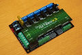
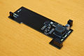
X3 prototype
X3 prototype
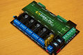
X3 prototype w/ power pack
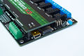
X3 prototype cover removed
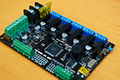
12-24v boost prototype
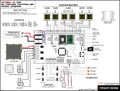
Wiring Diagram


User Installations
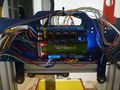
Running a Hadron Ordbot(mhensen)

<videoflash type="youtube">-mq8qUMBhyw|480|360</videoflash>
Files and Documentation
Get your Azteeg X3 up and running
Hardware
Tools required: Soldering Iron, Solder, Phillips Screw Driver.
1. Solder Connectors - Check that all your connectors are accounted and solder them one at a time. Ensure that you have a good solder joint and align each connector to make it look nice. One trick is to place the connector and solder just one pin to hold it in position, after soldering the rest of the connectors you will see if everything aligns well. Reheat the solder joint to re-position the connector, if all is good solder the rest of the pins.
2. Install micro stepping jumpers - These jumpers determine the micro stepping setting for your stepper drivers. These are labeled MS1, MS2 and MS3 on the board( see wiring diagram). Please check your drivers argumentation for specific settings. On most pololu style drivers ( stepsticks, SureStepr and pololu A4988) having all jumpers populated will give you 1/16th stepping.
3. Solder other connectors - If you are using other connections like the expansion pins, now is the time to solder them. Take the same precautions as mentioned above and check each solder point to make sure it has a good bond to the pins.
4. Visual check - Before wiring your board, do a quick visual check to make sure that there are no solder shorts, jumpers are pushed all the way down and nothing looks out of the ordinary.
5. Wire up your board - Open up the wiring diagram and pick a suitable location for your controller on your printer. Start wiring your board and please observe polarities and pin designations for endstops and thermistor connections.
The endstops need to be connected to the Common(C) and Normally Open(NO) pins of the switch. Please check the markings on your endstop switches as they may vary from model to model. If you have these mis-wired your motors wont move or will move only in one direction.
The thermistors sometimes come with insulators on the leads which is nice but others have bare leads, care should be taken that these dont short or come in contact with the heated bed traces or the body of your hot end. It could could render that particular controller pin inoperable or worse could kill the micro controller.
Wiring the motors can be a little bit tricky but not difficult. 1A and 1B is a pair and 2A and 2B is another, mis-wiring them could result in stutters or non-movement. A nice trick to find the wire pairing of your motor (if not shown on your manual) is to short 2 random wires on your motor and spin the shaft of the motor with your fingers. If its easy to spin you dont have a pair, if it feels as if its fighting the spin you have a pair. Wire them up and you still might need to flip wires if your motors dont move correctly.