Basics about switching loads with MOSFETs
Contents
Considerations about circuit dimensioning of low side MOSFET switches for hotend and heated bed
Abstract
Very often users claim problems with their hotend heater and heatbed outputs. This has several reasons. The biggest issue is that the RDS_on of the used MOSFETS is, driven with 5V gate voltage too low. The other issue is that the the reverse voltage that occurs, when the MOSFET switches from on to off state kills the transistor. This revese voltage is caused by the parasitic series inductance of the heatbed, hotend heater cartride or resistor. This article tries to generate understanding of what is happening.
Problem of MOSFET overheating
Some calculations
Given: Heatbed Power 150W @ 12V -> Heatbed current 12.5A
Example 1
Mosfet of Sanguinololu 1.3a
- RDS_on approx. 40mOhm @ Vgs = 5V (the resistance of the device in on-state when applying 5V to the gate)
- Package thermal resistance 80°K/W (this means with 1W thermal power loss the package heats up by 80°K) without additional heat spreader.
-> Thermal power loss of the MOSFET device: 12.5A² * 40mOhm = 6.25W -> Theoretical resulting device case temperature 6.25W * 80°K/W + 25°C (ambient temp.) = 525°C
This definitely kills the MOSFET to survive add a heat spreader with at least 15°K/W which results in a device temperature of approx. 120°C at room temperature.
Example 2
Mosfet of RUMBA
- RDS_on approx. 10mOhm @ Vgs = 5V
- Package thermal resistance incl. PCB area approx. 40°K/W
-> Thermal power loss of the MOSFET device 12.5A² * 10mOhm = 1.6W -> Theoretical resulting device case temperature 1.6W * 40°K/W + 25°C (ambient temp.) = 90°C
The device will survive.
Problem of reverse voltage killing the MOSFET device
Some Simulations to show the influence of these parasitics
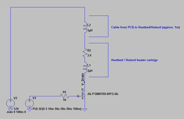
Typical parasitic inductances:
1. Heatbed MK2 650nH
2. Vishay 3.3 Ohms power resistor 2µH
3. Heater cartrige 12V 40W 3µH
4. 1 meter cable 1mm AWG18 1µH (rule of thumb)
(1-3 source posting Hardwarekiller)
Simulations (LTSpice)
Simulation schematic without freewheeling diode
Simulation results
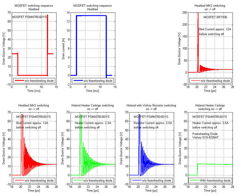
The two diagrams on the top left shows a single switching sequence from heatbed off - on - off The leftmost shows the voltage, the picture next to this the Drain current. You can see that the highest voltages occur when switching from on state to off state. All other pictures show a zoomed view of the drain-source voltage (VDS) at this event.
You can see that in the top rightmost diagram a voltage of approx. 250V(!) volts occures at the drain of the IRF7936. The device is rated only with 30V VDS. This voltage applys only 100ns and will not kill the device instantaneous but over time this overvoltage will lead to malfunction of the device.
The leftmost three diagrams in the second row show the VDS voltage for the PSMN7R0-60YS MOSFET used on RUMBA in different applications: Heated bed, Hotend with 40W heater cartrige and Hotend with Vishay heater resistor.
As you can see the VDS voltage is approx. 68V. The MOSFET device (PSMN7R0-60YS) is only rated at 60V. This is also out of the specification of the device. Sooner or later it will result in malfunction of the board.
Only the rightmost Diagram in the second row shows a VDS voltage which has no overshoot when switching from on to off state. What is the reason for this? The undrelying circuit is using a freewheeling diode across the load (heatbed, hotend). The schematics below shows the (simple) circuit change.
Simulation schematic without freewheeling diode
Now the bad news....
Most of the available printer electronics dont have these freewheeling diode! I found only three actual electronics that have it.
RUMBA, RAMS, Sanguinololu have no diode are from this point of view not well designed and do not prevent the MOSFET from overvoltage peaks!
Gen7, easy electronics, STB-electronics have the diode and prevent the MOSFET from overvoltage events
Some hints for selecting the right MOSFET.
- Consult the schematics of the electronics you intend to buy. Compare them to the examples shown in this
report and decide what to built or buy.
- Always look for the RDS_on @ Vgs=5V most Devices are specified at Vgs=10V
this makes a big difference in terms of RDS_on which is in this case (Vgs=10V) significantly higer
at 5V Vgs.
- Make sure that the allowed max. VDS is lager than your power supply voltage.
- Use a freewheeling diode across the load
The requirements on that diode are not very high. The reverse current through this diode is < 5A for approx. 0.5ms.
For example a simple 1N4001 diode can make the job. Its allowed forward currend is 30A(!) when the pulse time is below
8ms.

