COssel
Release status: working

Contents
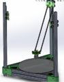
Overview
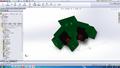
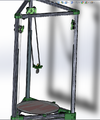
cOssel is a large, delta-type 3D printer. cOssel is an iteration of Johann's Kossel. Design intents are to:
- equip a dual head end effector,
- move the linear rails to an open design,
- equip a bowden extruder to accommodate geared steppers,
- fix the heated bed more robustly (i.e. no binder clips),
- increase the aluminum extrusion size to help scale the printer, thus use 20x20 instead of 15x15, and
- otherwise copy Johann's delta-bot intent.
Default configuration is setup for dual extruders, heated bed, and EE fan. The O in cOssel is intended to be significant as a commitment to using open designs, when applicable & feasible.
Models for the RP parts are located on the GitHub. Laser cut CAD is on the GitHub as well, or can be downloaded directly from the Ponoko link in the #BOM section.
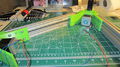
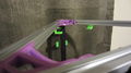
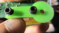
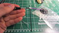
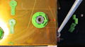
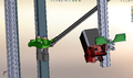
Non-contact Autoleveling
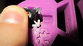
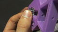
cOssel attempts to enable a low-power, non-contact autoleveling sensor as an alternative to using a retractable mechanical switch as used in other Rostock/Kossel deltas. This feature is still experimental as most IR sensors have not been proven repeatable, thus is still unfit for use. Video: Infrared Leveling
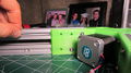
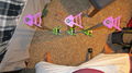
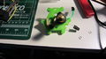
Auto Z Leveling IR Bed Probe
EE equipped with IR probe


Video
Assembly
The assembly process should take a short weekend to complete. Make sure that you have a standard tool set, including ball-end metric allen keys.
- Be mindful that once the aluminum extrusions are installed, in many places you are unable to insert extra extrusion nuts after the fact. It may be worthwhile to insert extra nuts for extendability on various 2020 members active slots.
- Warning: The images below do not always show the best build sequence. Read the text, which has been revised since all of the images have been taken for the easiest build sequence!
- Please, ask questions in the discussion page for help! Talk:cOssel
Pre-install nuts for easier extrusion install.
Use threadlock on frame members and linear rail for a robust assembly.


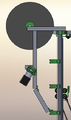
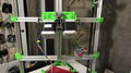
Main Vertical (Post) Assembly
Post Instruction
Post BOM
| Part | Qty |
|---|---|
| 2020_800 mm | 1 |
| 2020-300mm | 2 |
| open_rail-700mm | 1 |
| rp_base_vertex | 1 |
| rp_upper_vertex | 1 |
| motor_nema_17 | 1 |
| gear_drive_belt_gt2 | 1 |
| scrw_m3_set | 1 |
| scrw_m3_12 | 4 |
| wshr_m3 | 4 |
| scrw_m4_10 | 12 |
| scrw_m4_12 | 3 |
| wshr_m4 | 11 |
| nut_m4_extr | 14 |
| scrw_m5_10 | 15 |
| nut_extr_m5 | 15 |
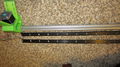
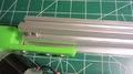
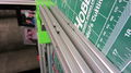
- Cut the bulk linear rail down to 700mm (or marginally less).
- Hold the base vertex up the 2020 as though you were about insert the post into vertex. Mark the height of the base vertex on the 2020 (how much of the 2020 the vertex hides).
- Insert 1x M5 extrusion nut into the rail.
- Stack the rail onto one another, align the slots, and place onto the 2020.
- Install 1x M5 10mm screw that came with the OpenRail kit through the rail into the M5 nut just inserted.
- Install the remaining hardware in each slot of the rail loosely.
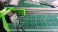
- Center the rail on the 2020. Recommended to use a ruler, and ensure that both ends of the rail are the same distance from the edge of the 2020.
- The slots of the OpenRail have wide slots, enabling you to install the rail non-coaxially with the with 2020. It is critical that both ends of the OpenRail be centered on the 2020!
- Install 2x 2020 x 300mm rails onto the sides of the base vertex.
- 8x M4 washer
- 8x M4 screw 10mm
- 8x M4 extrusion nut
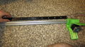
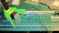
After centering the OpenRail about the center of the extrusion, secure the OpenRail to the extrusion. Torque from the center outwards, alternating sides


- Install electrical connectors on your motor wires.
- Install the drive pulley on your motors. Slide it closer to the motor body for now--you will adjust it later as required.
- Install the motor to the base vertex. Install 4x m3 washers and screws.
- On the post nearest and furthest your control board, have the wires exiting to the right.
- On the remaining post, have the wires exit towards the left.
- Install the 2020 into the base vertex.
- Insert 2x M4 nuts and secure the base vertex with M4 12mm screws and M4 washers.
Base vertex
Top vertex
Insert nuts
Insert nuts 2
Main vert complete


- Install the upper vertex onto the top of the post.
- Ensure the surface is flush.
- Designate one of the posts to be the near the electronics. We shall designate this as the 'X' motor, despite the motor not corresponding to cartesian motion. Y and Z shall be in reference to X, clockwise, from top-down view of the printer.
- If you have decided to install the wooden, corner, upper frame braces, insert 2x M4 extrusion nuts, and secure the rp_brace_top_vertex loosely with M4 washers and M4 12mm screws.
- Insert 4x M4 nuts on the outside channel of the 2020 to secure the primary, vertical raceway onto. Insert 4x M4 10mm screws and washers into these temporarily. Raceway installation will occur later.
- Insert a M4 nut, and secure the upper vertex with a single M4 12mm screw and washer.
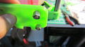
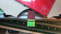
Carriages
Carriage Assembly Instruction
Post BOM
| Part | Qty |
|---|---|
| rp_flag_carriage | 1 |
| nut_m3 | 1 |
| open_rail_bearing | 8 |
| open_rail_nut_m5 | 14 |
| open_rail_scrw_m5_std_wheel_mnt | 4 |
| open_rail_shim | 2 |
| open_rail_shim_eccentric | 2 |
| open_rail_spacer_bearing | 4 |
| scrw_m3_20 | 1 |
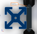
- Press a M3 nylock nut into the carriage nut cavity.
- Install the SST OpenRail kits on the non-drive side of the carriage.
- Install the Delrin OpenRail kits on the drive side of the carriage, in with widest, least constraining position. Snug the hardware, but do not fully tighten.
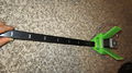
- Install the loose carriage onto the rail.
- Adjust the concentric nuts to engage the rail.
- Ensure there is no slop, such that there is no void between any wheels and the rail. Adjust the eccentric nuts no further than required. Tighten the hardware.
- Keep carriages installed.
Install belt tension nut
Flag 1
Flag 2
Eccentric nut
Eccentric nut 2
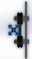
- Cossel slider 1
Slider 1
- Cossel slider 2
Slider 2
- Cossel slider 3
Slider 3


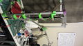
Upper Assembly
Upper Assembly Instruction
Post BOM
| Part | Qty |
|---|---|
| 2020-371 | 3 |
| bracket_power_supply_stablity_xy | 1 |
| rp_bracket_pwr_spply_tab | 2 |
| open_rail_shim_eccentric | 3 |
| nut_m4_extr | 20 |
| scrw_m3_12 | 6 |
| wshr_m3 | 12 |
| nut_m3 | 6 |
| scrw_m4_10 | 5 |
| screw_m4_15 | 15 |
| wshr_m4 | 6 |
| wshr_m4_fender | 3 |
Power Supply Supports

- Load upper 2020-371mm members with M4 extrusion nuts to support the following:
- optic end stops. (1x each SIDE, bottom face)
- power supply support tabs. (1x on SIDE1 bottom face, 1x on SIDE3 bottom face).
- wooden vertex braces (4x per outside face)
- Mounting to the rp_upper_vertex. M4 12mm.
- Secure each 2020 member to the upper vertex. Leave no space between the 2020 and the RP parts.
- Loosely install the rp_bracket_pwr_spply_tabs on SIDE1 and SIDE3. Use 2x scrw_m4_10 and 2x wshr_m4.
- Loosely install the power supply bracket (bracket_power_supply_stablity_xy). Use 3x scrw_m4_10 and 3x wshr_m4.
- Assemble the opto-endstop board, per the board level instructions. Use 2x scrw_m3_12, 2x wshr_m3, and 2x nut_3m.
- Assemble the optoboard to the rp_opto_mount using 2x scrw_m3_xx and 4x wshr_m3.
- Loosely install the opto-endstops. Use 1x scrw_m4_15, 1x wshr_m4, 1x open_rail_shim_eccentric, 1x m4_wshr_fender per unit.
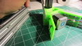
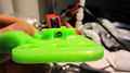
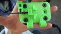
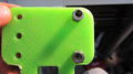
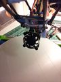
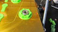
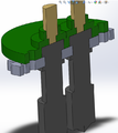
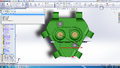
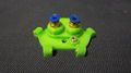
End Effector
End Effector Instruction
Post BOM
| Part | Qty |
|---|---|
| rp_end_effector | 1 |
| bracket_hot_end_groovemount_dual | 1 |
| extruder_maker_gear (hot end) | 2 |
| nut_extr_m5 (open_rail_kit_excess) | 2 |
| fitting_one_touch_4mm (OD) | 2 |
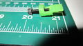
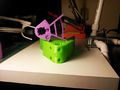
- Insert the hot ends into the hot end mounting bracket.
- Use a straight edge and a level to make sure the hot end tips are level with each other.
- Align the wires and connectors such that they may pass thru the rp_end_effector hole
- Press the hot end and joining bracket into the rp_end_effector. Some gentle twisting and pulling of the hot ends may be required.
- Place a 5mm extrusion nut under one of the bridges on the top of the end effector.
- Thread a fitting_one_touch_4mm through the top of the end effector , and engage the nut. Tighten!
- Look through the fitting. Ensure the that hot end hole is in clear view! The filament needs a straight path from the fitting into the hot end!
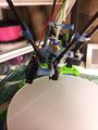
EE r5 - Fan Mount & Secured OneTouch Fittings
EE r5 - 2
EE r5 - 3
EE r5 - 4
HotEnd bracket and install 1
HotEnd bracket and install 2


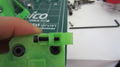
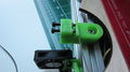
End Stops
End Stop Instruction
Post BOM
| Part | Qty |
|---|---|
| pcb_opto | 3 |
| rp_opto_mount | 3 |
| wshr_m4_fender | 3 |
| open_rail_shim [any spacer will be OK] | 3 |
| wshr_m4 | 3 |
| scrw_m4_15 | 3 |
| scrw_m3_12 | 6 |
| wshr_m3 | 12 |
| nut_m3 | 6 |
The following images show the end-stop terminal block on the end-stop board. I ended up removing the terminal blocks from the boards to reduce interference from the carriage assembly as it approached the Z_MAX home position.
- Install the pcb_opto to the rp_opto_mount.
- Install using scrw_m3_12's TOP-DOWN using wshr_m3s on both ends, and securing gently with nut_m3s.
- Note: you may consider adding small spacers between the pcb and the opto_bracket as the solder points prevent a flush mate. Thus, over-torquing the m3's flex the board and bracket. This is minimal, thus I have opted not to.
- Install the opto brackets to the upper frame assembly into previously inserted extrusion nuts.
- Use a scrw_m4_15, wshr_m4, open_rail_shim, and a wshr_m4_fender for each assembly.
End-stop stack installed
End stops 1
End stops 2
End stops 4


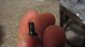
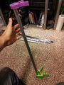
Rod Ends
Rod Ends Instruction
Post BOM
| Part | Qty |
|---|---|
| rod_ends | 12 |
| scrw_m4_set_20 | 12 |
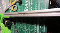
It is assumed that your push rods have already been cut to size by yourself or a vendor. If not, cut your rods to length.
- Place the rod end ball standing vertically on a stable surface.
- Place the rod end socket loosely over the ball end ball.
- Space a pair of needle nose pliers around the perimeter of the socket.
- Press firmly down and click the socket over the ball.
- Prepare the epoxy solution.
- Apply dab of mixed epoxy onto threaded 4mm dia, 20mm long set screw
- Thread set screw into rod end as deep as it will go
- Apply another dab of epoxy onto the set screws, this time, more generous
- Gently place the set screws into the carbon fiber tube.
- Firmly press both opposing rod ends together along the tube axis.
- Set rod to try. Ensure that rod ends are parallel with each other.

Step 1
Step 2

Step 3
Dab a tiny amount of epoxy onto the male side of set screws
Thread 4mm set screws into rod ends.
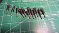
Prepared rod ends
Mix two part epoxy


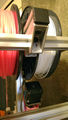
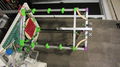
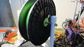
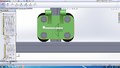
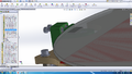
Frame - Spool Support
Frame - Spool Support
Post BOM
| Part | Qty |
|---|---|
| 2020-134mm | 1 |
| 2020-200mm | 3 |
| 2020-300mm | 1 |
| bracket_tee_2020 | 7 |
| rp_extruder_join_lower | 1 |
| rp_extruder_join_upper | 1 |
| scrw_m4_10 | 18 |
| wshr_m4 | 18 |
| nut_m4_extr | 5 |
- Install the 2020-200mm to the top of the frame.
- Secure using bracket_tee_2020 on both sides of the main top triangle, and use scrw_m4_10 and wshr_m4 fasteners in each hole. The extrusion nuts should have already been inserted.
- Center the 200mm extrusions, and space the outter two evenly away from the center piece such that your filament spools will fit in the void.
- Install a nut_m4_extr to the center 200mm extrusion.
- Install a nut_m4_extr to the 300mm extrusion, 2020-300mm.
- Secure a bracket_tee_2020 to the 300mm extrusion, and use scrw_m4_10 and wshr_m4 fasteners in each hole.
- Install the 300mm extrusion to the 200mm extrusion.
- Install 2x wshr_m4 and 2x scrw_m4_10 into both rp_extruder_join_lower & rp_extruder_join_upper.
- Insert an additional nut_m4_extr into the 300mm extrustion and the 134mm extrusion.
- Install the rp_extruder_join_x RP parts.
2020-200mm Installation 1
2020-200mm Installation 2
Spool Support CAD Side View
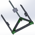
Flex reduction cross-members


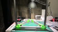
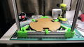
Bed
9
10
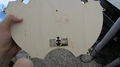
Install overtemp sensor
Install bed lock hardware
Heater PCB and cloth insulation


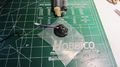
Filament Delivery
Spool Assy
Spool bearing cartridge 1
Spool bearing cartridge 2
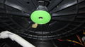
Spool bearing cartridge 3
Spool bearing cartridge 4


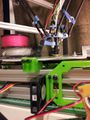
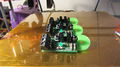
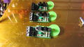
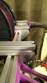
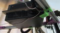
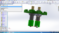
Extruders
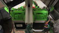
Ext 1
Ext 2
Extruders are heavy. They need support extrusions!


Final
Final Assembly Instruction
Final BOM
| Part | Qty |
|---|---|
| 2020_caps | (all) |
- Clip all caps into the 2020 extrusion. Edges may be sharp! Cap them for safety.
Wiring
Install power supply

Fan I/O
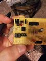
The RAMPS_1.4 board does not by default have sufficient IO to power three heaters and additional fans for the extruder heaters. Products exist already to serve this need, but I decided to build my own. I added a constant 12V drop for a always-on stepper driver cooling fan (so long as PS-ON is on), and a PWM circuit for a single extruder cooling fan. I shall use only one fan for both extruders. The #BOM includes links to purchase an off-the-shelf board for this purpose.
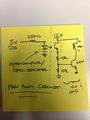
RAMPS Fan Extension Board Circuit
Fan Ext 1 (left half of board different circuit)
Fan Ext 2 (right half of board different circuit)
Fan Ext 3


BOM
The BOM for COssel is large, thus has been collapsed to not overflow the page. Expand the table below for a flat Bill of Material for procurement! The BOM is also formally maintained here in Microsoft Excel format (.xlsm): cOssel BOM. Please note:
- Electrical connectors are not covered in the BOM. It is assumed that the user has some experience with basic wiring.
- A supply of 22 AWG (+/- 2 AWG) is also good to have on hand. Even, better, some ribbon cable will do good things!
- Thermistors are not covered in the BOM. You will need to procure these on your own, as you need. I often equip the EPCOS 100K thermistor on my machines for the heated bed.
| Part | Total Qty | Vendor | MFG PN | Vendor PN | Notes | Link |
|---|---|---|---|---|---|---|
| 2020_cap | 16 | Misumi | HFC5-2020 | HFC5-2020 | Site is designed for commerical customers, but you can still setup an account. You must manually enter the part numbers into a purchase order. | [4] |
| 2020-134mm | 1 | Misumi | HFS5-2020-134 | HFS5-2020-134 | Site is designed for commerical customers, but you can still setup an account. You must manually enter the part numbers into a purchase order. | [5] |
| 2020-200mm | 3 | Misumi | HFS5-2020-200 | HFS5-2020-200 | Site is designed for commerical customers, but you can still setup an account. You must manually enter the part numbers into a purchase order. | [6] |
| 2020-300mm | 7 | Misumi | HFS5-2020-300 | HFS5-2020-300 | Site is designed for commerical customers, but you can still setup an account. You must manually enter the part numbers into a purchase order. | [7] |
| 2020-371mm | 7 | Misumi | HFS5-2020-371 | HFS5-2020-371 | Site is designed for commerical customers, but you can still setup an account. You must manually enter the part numbers into a purchase order. | [8] |
| 2020-50mm | 2 | Misumi | HFS5-2020-50 | HFS5-2020-50 | Site is designed for commerical customers, but you can still setup an account. You must manually enter the part numbers into a purchase order. | [9] |
| 2020-800mm | 3 | Misumi | HFS5-2020-800 | HFS5-2020-800 | Site is designed for commerical customers, but you can still setup an account. You must manually enter the part numbers into a purchase order. | [10] |
| bearing_608z | 4 | Amazon | 608z | Easily sourced | [11] | |
| bearing_624z | 6 | Amazon | 624z | Easily sourced | [12] | |
| bed_glass | 1 | SeeMeCNC | 26602 | 300mm, round borosilicate! | [13] | |
| belt_gt2_1700mm | 3 | OpenBuilds | Order by the foot. 304.8 mm / ft! | [14] | ||
| brace_frame | 6 | Ponoko | Legacy brace. Still may be viable and desired by some users. Included by default in Ponoko cut-out .svg | [15] | ||
| brace_spacer | 12 | Ponoko | Legacy brace. Still may be viable and desired by some users. Included by default in Ponoko cut-out .svg | [16] | ||
| bracket_heater_sppt_wood | 1 | Ponoko | Wooden piece. Laser cutting files on GitHub & ponoko | [17] | ||
| bracket_hot_end_groovemount_dual | 1 | Ponoko | Wooden piece. Laser cutting files on GitHub & ponoko | [18] | ||
| bracket_power_supply_stablity_xy | 1 | Ponoko | Wooden piece. Laser cutting files on GitHub & ponoko | [19] | ||
| bracket_tee_2020 | 9 | Misumui | HBLFSN5 | HBLFSN5 | Site is designed for commerical customers, but you can still setup an account. You must manually enter the part numbers into a purchase order. | [20] |
| cable_ribbon_10_conductor_15ft | 2 | SparkFun | CAB-1064 | Used for bulk-running the opto +V, SIG, & GND to the board. Also used for clean motor runs and I/O to the EE. Note, some have suggested this is too thin of wire gauge. User to decide | [21] | |
| drive_filament_dia | 2 | RepRap Sources | Mk7-like with 8mm bore to be compatible with phidgets geared steppers. | [22] | ||
| epoxy_two_part | 1 | Amazon | For gluing the rod ends to the carbon tubing | [23] | ||
| extruder_maker_gear | 2 | MakerGear | Make sure to configure your order for 1.75 barrel. | [24] | ||
| fan_40mm_12VDC | 2 | Amazon | Most 40mm 12VDC fans should do the trick | [25] | ||
| fitting_one_touch_4mm | 4 | Amazon | KQ2S04-M5A | 5mm thread req'd and 4mm OD tube receptable req'd | [26] | |
| gear_drive_belt_gt2 | 3 | OpenBuilds | 20 tooth or less is critical to prevent the belt from hitting the carriage | [27] | ||
| motor_nema_17 | 3 | Ultimachine | UMN17MTR | Std reprap motor | [28] | |
| motor_nema_17_geared_5.18_1 | 2 | Phidgets | 3317_1 | Extra torque required for long bowden path to hot end | [29] | |
| nut_extr_m5 (open_rail_kit_excess) | 69 | OpenBuilds | Do not order directly for hardware. You will have excess from your wheel kits which instead use the eccentric spacer. | |||
| nut_m3 | 35 | Fastenal | Nylon lock preferred | [30] | ||
| nut_m3_jam | 13 | Fastenal | Jam | [31] | ||
| nut_m4 | 20 | Fastenal | Nylon lock preferred | [32] | ||
| nut_m4_extr | 91 | Misumi | HNTTBS5-4 | HNTTBS5-4 | Site is designed for commerical customers, but you can still setup an account. You must manually enter the part numbers into a purchase order. | |
| open_rail_bearing | 24 | OpenBuilds | Do not order directly for hardware. You will have excess from your wheel kits which instead use the eccentric spacer. | |||
| open_rail_nut_m5 | 14 | OpenBuilds | Do not order directly for hardware. You will have excess from your wheel kits which instead use the eccentric spacer. | |||
| open_rail_scrw_m5_std_wheel_mnt | 12 | OpenBuilds | Do not order directly for hardware. You will have excess from your wheel kits which instead use the eccentric spacer. | |||
| open_rail_shim | 9 | OpenBuilds | Do not order directly for hardware. You will have excess from your wheel kits which instead use the eccentric spacer. | |||
| open_rail_shim_eccentric | 6 | OpenBuilds | Stock availability can be shaky. May need to adapt a different eccentric nut. | [33] | ||
| open_rail_spacer_bearing | 12 | OpenBuilds | Do not order directly for hardware. You will have excess from your wheel kits which instead use the eccentric spacer. | |||
| open_rail_wheel_delrin | 6 | OpenBuilds | Wheel kit | [34] | ||
| open_rail_wheel_sst | 6 | OpenBuilds | Wheel kit | [35] | ||
| open_rail-700mm | 3 | OpenBuilds | Order the 1000mm's and cut to length | [36] | ||
| pcb_arduino_mega | 1 | Ultimachine | Note: The RAMPS stack below includes a MEGA 2560. Make sure not to double buy! | [37] | ||
| pcb_fan_extension_board | 1 | Geeetech | Or make your own! cdaringe opto-extension board | [38] | ||
| pcb_heater | 1 | Ultimachine | Prusa Heater | [39] | ||
| pcb_opto | 3 | Ultimachine | Std opto's | [40] | ||
| pcb_RAMPS_stack | 1 | Ultimachine | Single Z, not dual Z configuration. | [41] | ||
| pcb_sd_ramps_extension_board | 1 | Geeetech | Strongly recommended as pausing issues occur when printing via USB | [42] | ||
| power_supply | 1 | Thermaltake | TR2 TR-700 | N82E16817153167 | ATX PS. Quiet, reliable. | [43] |
| rod_carbon_330mm | 6 | Hobby-Lobby | GXT5540 | Must be cut to size. 3x 1000 rods will satisfy a std build | [44] | |
| rod_ends | 12 | Amazon | 5347 | 4mm OD receptable, 3mm thru-hole ball-ends | [45] | |
| rod_threaded_8mm-271mm | 1 | Grainger | 5/16" rod is ~8mm too. You can buy 5/16" rod at hardware stores (i.e. Home Depot) for a couple of bucks. | [46] | ||
| rp_base_vertex | 3 | RP | RP | RP | Files on GitHub | [47] |
| rp_block_bed | 3 | RP | RP | RP | Files on GitHub | [48] |
| rp_brace_top_vertex | 3 | RP | RP | RP | Files on GitHub | [49] |
| rp_bracket_axle_spool | 3 | RP | RP | RP | Files on GitHub | [50] |
| rp_bracket_lateral_sppt | 4 | RP | RP | RP | Files on GitHub | [51] |
| rp_bracket_lateral_sppt_mirrored | 4 | RP | RP | RP | Files on GitHub | [52] |
| rp_bracket_pwr_spply_tab | 2 | RP | RP | RP | Files on GitHub | [53] |
| rp_bracket_RAMPS | 1 | RP | RP | RP | Files on GitHub | [54] |
| rp_end_effector | 1 | RP | RP | RP | Files on GitHub | [55] |
| rp_extruder_cossel_bowden_mirrored | 2 | RP | RP | RP | Files on GitHub | [56] |
| rp_extruder_join_lower | 1 | RP | RP | RP | Files on GitHub | [57] |
| rp_extruder_join_upper | 1 | RP | RP | RP | Files on GitHub | [58] |
| rp_flag_carriage | 3 | RP | RP | RP | Files on GitHub | [59] |
| rp_idler | 1 | RP | RP | RP | Files on GitHub | [60] |
| rp_idler_boss_bearing_8mm | 2 | RP | RP | RP | Files on GitHub | [61] |
| rp_idler_mirrored | 1 | RP | RP | RP | Files on GitHub | [62] |
| rp_idler_strut | 2 | RP | RP | RP | Files on GitHub | [63] |
| rp_mount_fan_ee | 1 | RP | RP | RP | Files on GitHub | [64] |
| rp_mount_fan_motor_drivers | 1 | RP | RP | RP | Files on GitHub | [65] |
| rp_opto_mount | 3 | RP | RP | RP | Files on GitHub | [66] |
| rp_plate_slider | 3 | RP | RP | RP | Files on GitHub | [67] |
| rp_upper_vertex | 3 | RP | RP | RP | Files on GitHub | [68] |
| scrw_finish_#6 | 1 | Fastenal | Thermal switch is not required, but strongly recommended for safety | |||
| scrw_m3_10 | 8 | Fastenal | Pan head & SST preferred when applicable. | |||
| scrw_m3_12 | 18 | Fastenal | Pan head & SST preferred when applicable. | |||
| scrw_m3_15 | 14 | Fastenal | Pan head & SST preferred when applicable. | |||
| scrw_m3_20 | 17 | Fastenal | Pan head & SST preferred when applicable. | |||
| scrw_m3_25 | 2 | Fastenal | Pan head & SST preferred when applicable. | |||
| scrw_m3_35 | 2 | Fastenal | Pan head & SST preferred when applicable. | |||
| scrw_m3_50 | 4 | Fastenal | Pan head & SST preferred when applicable. | |||
| scrw_m3_set | 5 | Fastenal | Only order this if your timing pulleys and filament drive gear do not come with their own. They nearly always do. | |||
| scrw_m4_10 | 47 | Fastenal | Pan head & SST preferred when applicable. | |||
| scrw_m4_12 | 30 | Fastenal | Pan head & SST preferred when applicable. | |||
| scrw_m4_15 | 25 | Fastenal | Pan head & SST preferred when applicable. | |||
| scrw_m4_20 | 12 | Fastenal | Pan head & SST preferred when applicable. | |||
| scrw_m4_25 | 4 | Fastenal | Pan head & SST preferred when applicable. | |||
| scrw_m4_8 | 22 | Fastenal | Pan head & SST preferred when applicable. | |||
| scrw_m4_set_20 | 12 | Fastenal | Rod End Mounts | [69] | ||
| scrw_m5_10 (open_rail_kit_excess) | 67 | OpenBuilds | Do not order directly for hardware. Hardware comes kitted with your rail. | [70] | ||
| spring_m3_extruder | 4 | Home Depot | Only 1x spring kit reqd | [71] | ||
| spring_m4 | 7 | Home Depot | Only 1x spring kit reqd | [72] | ||
| switch_thermal | 1 | Amazon | Amico KSD301 | Recommended for safety | [73] | |
| tab_felt | 3 | (no vendor data entered) | This is a thermal barrier between the bed and the bed clamp. Simply household cloth shall suffice. | |||
| tubing_4mm_bowden_1000mm | 2 | MakerShop | Any common RepRap 4mm tube shall suffice | [74] | ||
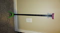
| wire_raceway_10in | 1 | McMaster-Carr | 7578K73 | The 6'6" is enough for your full build | [75] | |
| wire_raceway_25in | 1 | McMaster-Carr | 7578K73 | The 6'6" is enough for your full build | [76] | |
| wire_raceway_5in | 2 | McMaster-Carr | 7578K73 | The 6'6" is enough for your full build | [77] | |
| wire_raceway_8in | 1 | McMaster-Carr | 7578K73 | The 6'6" is enough for your full build | [78] | |
| wire_wrap_10ft | 1 | McMaster-Carr | 7378K41 | Pick a color! You may use 8+ ft. | [79] | |
| wshr_4mm | 8 | Fastenal | SST preferred | |||
| wshr_m3 | 69 | Fastenal | SST preferred | |||
| wshr_m4 | 145 | Fastenal | SST preferred | |||
| wshr_m4_fender | 6 | Fastenal | SST preferred | [80] |
FAQ
Question?
Answer. Cdaringe (talk) 16:47, 17 April 2014 (PDT)
Images
Cossel Corners
Cossel 1
Belt path (old carriage)
Archive - 1st rev tower
Archive - rev2 tower with EE
Archive - rev3 tower
Archive - rev4 tower
Rev5 tower
Belt path
Dual Extruder, r1
Dual Extruder 20mm sep
Glass Bed Lock
Airtripper Suspended
Dimensions (for f/w), EE
Dimensions(for f/w), Carriage
Dimensions (for f/w), DELTA_CARRIAGE_OFFSET
Dimensions (for f/w), DELTA_DIAGONAL_ROD
Dimensions (for f/w), DELTA_EFFECTOR_OFFSET
Dimensions (for f/w), DELTA_SMOOTH_ROD_OFFSET
Dimensions (not req'd), BedC-HotEndC with vertical rods
Bed Mounting Assembly
Lightweight rendering example
Vert sliders
Vert slider interference & ref
- Cossel ee top.JPG
EE r1, 1
EE r1, 2
- Cossel probe 1.JPG
Probe 1
- Cossel probe2.JPG
Probe 2


