CamRap
Release status: unknown
| Description | Documentation of Camrap R&D
|
| License | |
| Author | |
| Contributors | |
| Based-on | [[]]
|
| Categories | |
| CAD Models | |
| External Link |
Contents
Overview
//Under construction, more coming soon!
Camrap is intended to be cheap, safe (no high temperatures) and very high resolution.
The main requirements of the Gada Prize are:
- Print at least three different materials, including one that is usefully electrically conductive.
- Demonstrate the ability to print electronic circuit boards.
- Any print beds must be of a material which may be reused with minimal refurbishment for at least 20 print cycles.
- Maintain a total materials and parts cost under $200.
- 90% of the volume of the device's components shall be printed.
- Demonstrate a build volume greater than 300mm[11.81in] x 300mm[11.81in] x 100mm[3.94in].
- The capacity to print a full set of components for a complete replica of itself within 10 days unattended save for clearing no more than one printer head jam.
- The ability to print autonomously without a PC attached.
- Uses no more than 60 watts of electrical power.
Key Concepts
Positioning
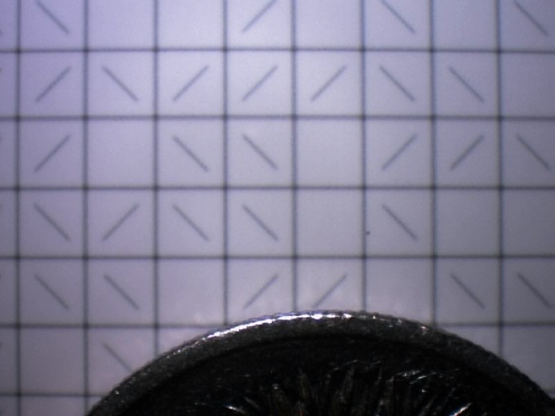
Camrap is named for it's positioning system, which uses a webcam as a means to read a 2d image which encodes X and Y position. Z-axis positioning will likely be "stepped" and have its position inferred as with stepper motors.
The position detection works by processing a captured image of a printed grid, whi8ch is attached to the "build platform" and moves with it in X and Y.
The horizontal and vertical line positions can be measured quite accurately by averaging subpixel line positions at each pixel along the line. This determines the image centre point in partial grid units, and the positions of each line in relation to the whole grid can be determined from the diagonal lines. The diagonal lines represent "digits" which can be either /, \ or blank, and each 4*3 sub-grid has a unique pattern of these.
Structure
The current (work-in-progress) prototype Camrap uses 10mm extruded aluminium tube, FIMO polymer clay and some balsa wood as unprinted parts.
The current design is a similar shape to Huxley, but has only single tubes as edges, two of which are also used as X-axis rails. The Y-axis travels with the X-axis carriage.
Printed parts will be some form of polymer clay if possible. "Metal" clays are available which can be fired to remove a binder and leave a sintered metal product behind.
If that doesn't work well enough though, an existing Reprap extruder design could be used.
Because positioning is measured rather than inferred from motor steps or encoder wheels, drive options are not limited to stepper motors. Currently cheap continuous rotation servos are used, but they may prove to be underpowered.
Control Systems
A PC, webcam and an Arduino. Possibly an Android mobile phone could be substituted for the PC and webcam (possibly the Arduino too).
Workbook
General Notes
In accordance with the official Gada Prize rules regarding documentation and transparency - as interpreted by the RepRap Core Team and others - all documentation for this project will take place here in this wiki. If there happen to be any "Other Spaces" out there that have documentation for this project, then such information is posted there only after it is posted here.
- The following notes help to keep this workbook in a neat and orderly condition and shall be generally adhered to throughout all levels of documentation.
- All dimension and temperature nomenclature shall include both SI and Imperial units. SI units shall be first followed by Imperial units in brackets. Examples: 100mm[3.94in] and 40°C[104°F]
Project log
24 JUN '11
Wiki page with short overview created.

