Coating of liquids in 3D printing
This page describes the coating of liquids in 3D printing. The introduction of transparent polygon scanners in the field of photo-polymerization has a profound effect. All the coating patents, were defined under the assumption that transparent polygon scanners do not exist. This creates a wide array of loop holes. This article is written is to create prior arts so these loopholes can be used in the next 20 years :-). The expiration dates of patents are estimates. There are several ways to extend patents. This is complicated as regulation varied over the past 20 years.
Prior art
Literature
The following literature is key in this field.
LIQUID FILM COATING; Stephan F. Kistler, Peter M. Schweiz
It describes coating as in general. Liquid film coating has been key to industrial processes for a long time.
Dip & Blade Coating
- patent: US5651934 (expired, 2008)
- description:In the first implementations of Stereo Lithography Apparatus (SLA). Parts were dip coated. To speed up the process, deep dip & blade coating was invented.
Dip & blade coating was used in SLA 250 or SLA 500 systems of 3D systems. Later, an update was made available to use an active blade. Up to 2017, systems sold by 3D systems were still using an active blade retailed as "Zephyr blade"
- process settings; blade clearance, blade gap, number of sweeps, velocity per sweep, layer thickness & illumination time, deep dip distance
- properties: leading edge hump, scoop out, flow back and lift force
- blade design: symmetric to allow sweeps in both direction, multi-dent or tri-dent
- physics: the key equation are provided by the theory of boundary layers, see https://en.wikipedia.org/wiki/Boundary_layer
- end users: 3D systems (no longer used), R&D
Slot Die Coater
- literature: Flows in thin Film Coating, Christian Kuschel
- end users: none in 3D printing
Applicator Bar
- patent: EP 0807014 B1 (expired 2015 or 2016, not sure)
- process settings: blade clearance, velocity per sweep, blade gap
- blade design: symmetric to allow sweeps in both directions
- sensors: differential pressure sensor to measure internal pressure applicator bar versus external pressure, laser to measure internal liquid height
- physics: boundary layer theory, law of communicating vessels, Wilhelmy plate method
- end users: Prodways, 3D Systems (sold as Zephyr recoater)
- literature: Process Errors and Aspects for Higher Resolution in Conventional Stereolithography, Carsten Tille // Recoating issues in stereolithography, Renap and Kruth // A study of recoating in stereolithography, D T Pham and C Ji
Curtain coating
- patent: EP0928242 (expired 2016 or 2017, not sure)
- challenges: teapot effect, start-up distance, curtain guides, wind shield, curtain edges must be outside vat, heel, air entrapment
- end users: Materialise
- literature: A study of the behaviour of a thin sheet of moving liquid, D.R. Brown (1960) // HIGH-SPEED CURTAIN RECOATING FOR STEREOLITHOGRAPHY (M. Gilio, J.-P. Kruth, and P. Vanherck)
Silicone release coating
- patent: US7052263B2 (expiration date 2023-4)
- materials: silicone, silicon with Teflon
- notes; There are some key differences between European and US version. In the European version both the sides of the through and the transparent plate are coated. If the sides are not coated, one does not infringe the patent. The US version is less specific and as a result Formlabs now faces a lawsuit.
tilting or movement of build plate can be beneficial, silicone can be coated with Teflon via heat treatment.
The Teflon is used to protect the silicone as photo-polymers can degrade silicone, which reduces the lifetime.
Continuous Liquid Interface Processing (CLIP)
- abbreviations; Continuous Liquid Interface Processing
- patent: WO 2014126837 A2 (expiration date 2034, not sure)
- materials: Teflon AF
- note: CLIP (Continuous Liquid Interface Processing) also uses a non-common acrylate, i.e. a polyurethane acrylate. Polyurethane can be strongly inhibited by oxygen (J. Mater. Chem., 2011, 21, 14325). Carbon 3D fixes this via post-processing. CLIP does not have stair-stepping and can be used to build flexible parts.
Flex VAT
- Patent; US4575330 A The patent is now only used for marketing purposes; figure 4 technology etc. .
- Note; flexvat is cheaper than glass with silicone as Teflon film is easier to replace, the main disadvantage is that it is less accurate due to bulging of the film. CLIP also uses a Flex VAT but with a Teflon AF film.
Transfer Substrate
- industrial usage: Admatec WO2015107066, Lithoz (rotating disk, Lithography-based Ceramic Manufacturing (LCM), Patent unknown), Carima Master EV (video, ADD NUMBER), TNO EP20090164821, US8777602B2.
- note: a liquid with a part gives a non-constant boundary condition, by the use of a transfer substrate the boundary condition is fixed, transfer substrates are ideal for filled slurries, admatec patent is actually an illumination method and not a recoating method (it is about a masking screen)
Flow Photo-polymerization
- Patent; example here US7709544B2
- Description; due to high flow and oxygen inhibition the part does not polymerizes up to the end of the tubes,
- Note: tubes most likely fabricated with Teflon AF (add reference)
Claims
Flow Photo-polymerization
A transparent polygon scanner used in flow photo-polymerization. It is used to illuminate a Teflon or Teflon AF tube where a liquid flows through. Another option would be a glass tube. The glass tube might be coated internally with silicone. If the flow is very slow as compared to the rotation speed of the polygon areas are illuminated multiple times. A part could then be grown due to these multiple exposures in a process similar to that of Continuous Liquid Interface Processing.
Dual applicator bar
The Zephyr blade of 3D systems is symmetric so it can coat in two directions. If an array of transparent polygon scanners is combined in one unit with an applicator bar; this is no longer the case. The symmetry is broken. As a result, we claim the combination; applicator bar, array of transparent polygon scanners and applicator bar see figure applicator bar. In addition we claim that this applicator bar is the same as the one by 3D systems and in addition it has an inlet to pump fluid into the applicator bar or an outlet to suck fluid up via the applicator bar. Furthermore, we claim this applicator bar has pressure sensor which measures the difference between the internal and ambient pressure. Finally, we note that in the case of powder the order would be counter-rotating roller, array of transparent polygon scanners and counter-rotating roller.
Conveyor belt
An array of transparent polygon scanners used in an conveyor belt printer. Examples are Google's Ara or TNO's Printvalley.
Through with protrusion
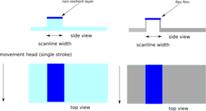
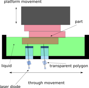
In bottom-up photo-polymerization see US4575330 A, Envisiontec came up with the idea to coat the glass with silicone, see US7052263B2. If a single transparent polygon scanner is used, the scanner is not able to illuminate the substrate at once. This scanner must be moved in two directions. One of the key problems, in bottom-up photo-polymerization is the transport of fluid to form the next layer. The contact between part and substrate must be minimal to facilitate the flow of liquid. Therefore only the area which is illuminated by the transparent polygon scanner in a single snake like lane should be in contact by the part. There is trough for holding a liquid on top of a plate. This through is semi-transparent and has a flat protrusion which can be brought in contact with the part during illumination. The transparent polygon scanner moves along the surface of this protrusion to project a single lane. After projection, the part is separated. The through is moved sideways and the part is again brought into contact. The transparent polygon scanner is used to form the next lane. This protrusion can be a flat glass substrate coated with a resilient layer, e.g. silicon see figure 1. This protrusion can also be a flex vat. This flex vat might be created with Teflon or Teflon AF. If the flex vat is created with Teflon AF, the photo polymerization process must be carried out so that it does not result into contact with the film; i.e. the so called deadzone of Carbon 3D must not be solidified. If this is not done, no separation force is required and flexible parts can be built.
Naturally, the through can have multiple protrusions if multiple transparent polygon scanners are used. In the the figure two glass protrusion with silicone as resilient layer are shown. These protrusion could also be formed by a flexible foil as has been depicted earlier.
Transfer substrate
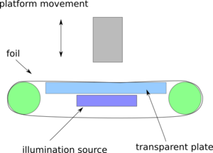
Key to Admatec's solution is the usage of a masking screen. In the case of a transparent polygon scanner, this is not needed. We propose a system where the foil is reused. To do so the foil is rotated around a glass plate and the projection is in between. The projection is formed by moving a transparent polygon scanner in a snake like manner or in a single pass.
CLIP claims
Concurrently advancing away
In the through with protrusion described above. In specific, the through with the flex vat formed by Teflon AF. It is important that the carrier is not concurrently advancing away (see claim 1, WO2014126837 A2). On the contrary, the carrier or part is static and first illuminated in a snake like pattern by moving the head and the through. As a result, it is not under claim one of CLIP. After a full snake movement, the carrier or part might be moved. Another option would be to make the whole through the same as Carbon 3D, i.e. a flex vat with Teflon AF. Now it could be possible to expose it in a single pass with transparent polygon scanners. Still, the through can not be concurrently advancing away as one must wait until the end of a pass.
Stair step minimization
As described above, the part is static and not concurrently advancing away. One might conclude that this result in stair stepping. This depends on the way the illumination takes place. It could be possible to move the scan head so slowly that the zone between the part and the plate is illuminated multiple times. That is each lane is not exposed once but effectively multiple times during the same movement. The amount of times this is done can be increased to reduce stair stepping.
NOTES
SLA is a trademark. Please use the term photo-polymerization printer in RepRap circles.


