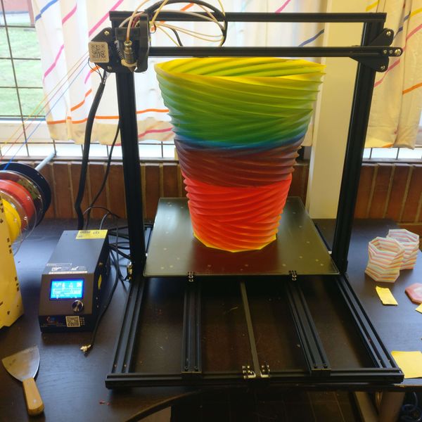
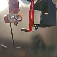
Creality CR-10 Diamond
Creality CR-10 Diamond
Release status: Development
| Description | Creality CR-10 Diamond
|
| License | |
| Author | |
| Contributors | |
| Based-on | |
| Categories | RepRap Color 3D printing
|
| CAD Models | |
| External Link |
Diamond Hotend upgrade guide for the Creality CR-10 family
This is the official build guide intended for those who wish to modify a Creality CR-10 for the Diamond Hotend.
The guide cover the family of Creality CR-10 (CR-10, CR-10S, CR-10 S4, CR-10 S5)
A little warning: this procedure will most likely void warranty on your device, so before proceeding please read this guide thoroughly and be sure you know and understand what you are about to do.
Contents
Part list
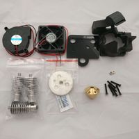
These are the parts needed for upgrading with the Diamond Hotend. For printed parts see the Thingiverse link at the bottom of this page.
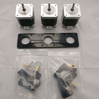
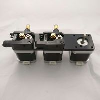
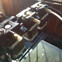
Full kit for Creality CR-10 Diamond Hotend Upgrade
Electronics
- 1 x Stepper Expander X2
- 2 x Stepstick
- 3 x Stepper Motor
- 2 x Stepper Motor Cable 1200mm
- 1 x Fan 12V
- 1 x Blower 12V
3D printed mount kit
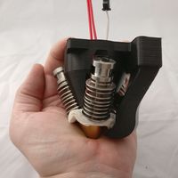
Diamond Hotend
- 1 x Diamond Nozzle 1.7 mm version
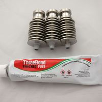
- 3 x E3D Lite6 heatsink with bowden fitting
- 1 x Diamond Hotend Insulators
- 1 x Creality Diamond Hotend Upgrade Special Parts
Extruders
- 2 x Creality Extruder
- 2 x Creality Extruder Drive Gear
- 3 x Bowden tube
Assembling
Hardware
- Dismount the original extruder.
- Unscrew the fan mount and cut the wires for the fans. Cut them close to the fans as we need the original fan wires to solder onto the new fans. Please make a note of which wires go to the heatsink fan and which go to the print blower.
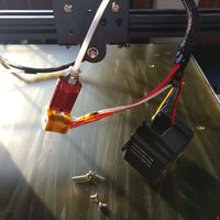
- Unscrew the original hotend and release the heater cartridge and thermistor for the hotends heat block. We need the heater cartridge and thermistor to insert into the Diamond Nozzle. Do not cut the wires but if the heater cartridge and thermistor is not fitted with connectors, we recommend to add them for ease of installation, but it's not necessary.
- Mounting the Diamond Hotend.
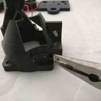
- Insert two M3 nuts into respective slots of the 3D printed mount. One on each side.
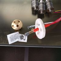
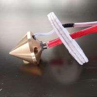
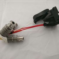
- Feed the heater cartridge through the insulators center hole (you can use all 3pcs insulators for extra insulation, however 1pcs can do it), feed the thermistor through the insulators small hole.
- Add heat paste to the tip of the thermistor and the sides of the heater cartridge. Do not use too much heat paste, as it can be hard to insert the heater cartridge fully into the nozzle.
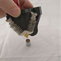
- Insert the heater cartridge fully into the center hole of the nozzle and insert the thermistor all the way into the bottom of the small hole of the nozzle. It's important to have the heater cartridge fully inserted or else the heatsinks can't be mounted correctly
- Before screwing in the heatsinks, we recommend to use some liquid gaskets or PTFE tape on the threads, to prevent leaking.
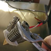
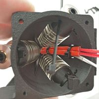
- Carefully put the thread through the insulator and screw it into the nozzle. Make sure each heat sink will not touch the side of the heater cartridge but they will overlap it and prevent it to fall out. If the heatsink touches the side of the heater cartridge, it's because the heater cartridge is not inserted fully into the hole or it's longer than 20mm. Tighten each heatsink with a plier. Do not overtighten as it can break the neck of the thread
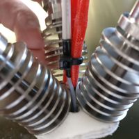
- Fix the wires from the thermistor with the wires from the heater cartridge with a zip tie. Make sure the thermistor is fully inserted into the bottom of the nozzle.
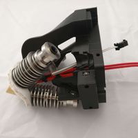
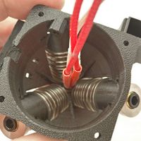
- Feed the wires into the 3D printed mount and carefully slide in the nozzle with heatsinks.
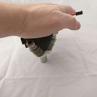
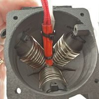
- The heatsinks will click into the mount with a firm push. It takes quite some force to click the heatsinks into place and i have two techniques i use. You could use the palm of your hand to press on the tip of the nozzle but it is painful. Another technique is to use a large nut or similar item for the nozzle tip, to avoid using force directly onto the tip. Never use any force directly on the tip of the nozzle, as it will deform easily
- Inspect each heatsink if its fully inserted into the 3D printed mount.
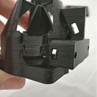
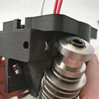
- Fix each heatsink with a zip tie through the 3D printed mount.
- Fix the heater cartridge and the thermistor wires with a zip tie through the holes in the 3D printed mount.
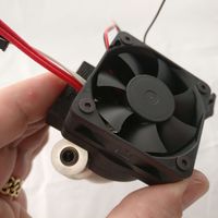
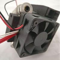
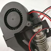
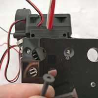
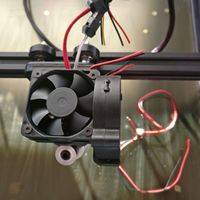
- Use 4pcs M3x20mm countersunk screws to fasten the fan on top of the 3D printed mount. Feed the heater cartridge and thermistor wires out the slot in the back. Make sure the fan is oriented as the picture to ensure the airflow to go into the mount
- Use 1pcs M3x20mm countersunk screw to fasten the blower to the side of the 3D printed mount.
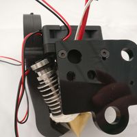
- Use 2pcs M3x20mm countersunk screws to fasten the lasercut hotend mount to the 3D printed mount.
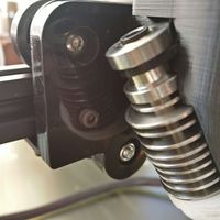
- Use 1pcs M3x10mm screw to fix the complete Diamond Hotend assembly onto the X-carriage.
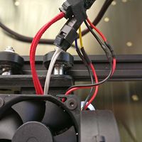
- Solder the wires for the fan and the blower. Make sure the wires for the original heatsink fan will connect to the new top mounted fan and the wires for the original side mounted blower, will connect to the blower fan. The red will connect to red wire and the black to black. Sometimes there will be a blue and yellow wire for the blower fan and here the yellow will connect to red and the blue wire to the black.
- Dismount the original extruder from the frame and remove the original extruder motor. The motor will be replaced with a more powerful motor.
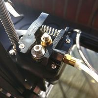
- Unmount the drive gear from the original extruder and mount it on one of the new and more powerful motors. Mount the 2pcs extra drive gears on the remaining motors.
- Mount the 2pcs extruder motors onto the left side of the laser cut extruder mount. Use 1pcs M3x12mm countersunk screw, 1pcs M3x20mm screw and 2pcs M3x12mm screws to fix them.
- Mount the extruder assembly plate underneath the metal frame and insert the 3. extruder motor from underneath and the extruder from the topside. Use 1pcs M3x16mm countersunk screw, 1pcs M3x25mm screw and 2pcs M3x16mm screws to fix them (please note the screws are longer for this extruder, to compensate for the extra metal frame in between)
Electronics
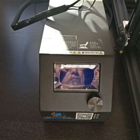
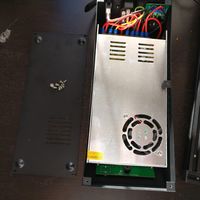
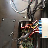
- Put the electronic controller box on it's side and unscrew the 4pcs screws (the screws will fix the power supply inside the box).
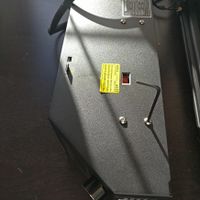
- Flip the box upside down and unscrew the 5pcs screws holding the bottom plate.
- Release the power supply and move it aside. No need to dismount the wires.
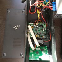
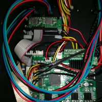
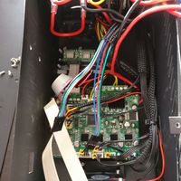
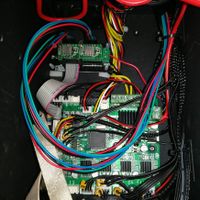
- With the power supply set aside all necessary steps for installing the electronics can be done, without removing the mainboard and you don't risk damaging it or connecting it wrongly. The pictures shows a mainboard completely removed from the box, but it's only done to make better pictures.
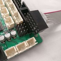
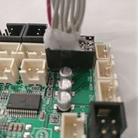
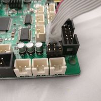
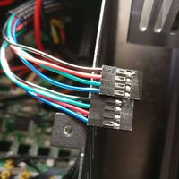
- First insert the special cable onto the 4x3pin connector on the mainboard. Make sure the connector is placed correctly with the soldered wires above the pins.
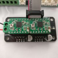
- Insert the Stepsticks into the Stepper Expander as the picture illustrate. Make sure you orient the Stepsticks correctly.
- Add the heatsinks to each chip on the Stepsticks.
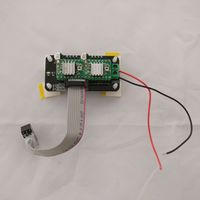
- Screw a piece of red and black wire to the screw terminal of the Stepper Expander.
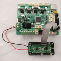
- Add the 4pcs PCB standoffs to the Stepper Expander and fasten it to the bottom of the electronic box next to the mainboard.
- Attach the ribbon cable to the Stepper Expander and connect the red and black wire to the screw connector of the mainboard. Alternatively you can connect the wires directly to the screw terminal of the power supply.
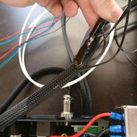
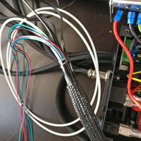
- For the two extra extruders we need two extra motor wires feed into the electronic box. With some skill you can have the feed into the same braided sleeve as the other extruder wire.
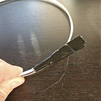
- Use a piece of 3mm filament as a guide wire, to push the motor wires through the braided sleeve.
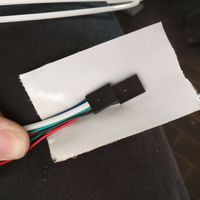
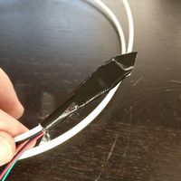
- First use a piece of tape to fasten the motor cable connectors to the end of the guide wire.
- Push the wires through the braided sleeve into the box.
- With the wires feed into the electronic box, please make sure the wires in the connectors are mounted correctly. With the motor attached in the other end, you should measure low resistance between pin 1+2 and pin 3+4 of each connector. If not please rearrange the pins in the connector. The pins can be pulled out of the connector by lifting the plastic clip with a needle.
- Insert both motor wires into the 4pin headers on the Stepper Expander. If it later turns out the extruders turns in the wrong direction, you can just reverse the motor wire connector.
- Insert the power supply into the electronic box and fasten with the 4 screws on the side.
- Mount the bottom plate with the 5 screws.
Firmware
- Before attaching all cables and do any testing, we need to firmware upgrade the electronic.
- Download Arduino here
- Download firmware for your 3D printer here
Sources
Part files
- "Diamond mount for Replicator/Duplicator" on Thingiverse - http://www.thingiverse.com/thing:899168
- Z-endstop_holder.stl
- MK9_wide_right.stl
- S2M_beltclamp.stl
- Wanhao Diamond cooler shield ver3.stl
- Wanhao X-carriage ver3.stl
- Flashforge Creator Pro LCD panel front.stl
- Diamond Hotend Insulator - http://www.thingiverse.com/thing:720520/#files
- diamond_thermal_isolation.dxf
Links
- This guide - http://reprap.org/wiki/Duplicator_Diamond
- Diamond Hotend general guide - http://reprap.org/wiki/Diamond_Hotend
- Stepper Expander - http://reprap.org/wiki/Stepper_Expander
- Adding more extruders - http://reprap.org/wiki/Adding_more_extruders
- Current limiting your stepper drivers, see section "current limiting" - http://reprap.me/pololu.html
