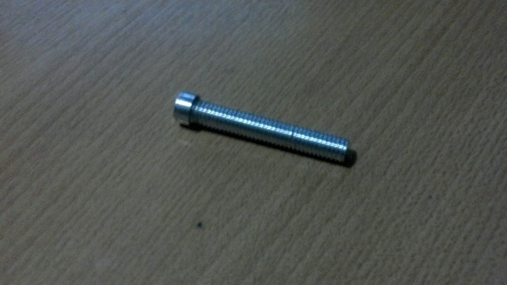
Crispy HotEnd
The parts of the extruder that get hot enough to melt plastic, or potentially other materials. As opposed the cold end, which is generally made from printed thermoplastic that needs to stay cool or it will melt / deform. Hot end parts use materials that can stand up to ~240 C heat (for current thermoplastic extrusion). The hot end usually refers to the tip of the extruder as it should be hottest there.
For a list of comparing hotends see Hot End Comparison.
For general theory useful for people creating improved hot ends, see Hot End Design Theory.Category:HotEnd
|
English • العربية • български • català • čeština • Deutsch • Ελληνικά • español • فارسی • français • hrvatski • magyar • italiano • română • 日本語 • 한국어 • lietuvių • Nederlands • norsk • polski • português • русский • Türkçe • українська • 中文(中国大陆) • 中文(台灣) • עברית • azərbaycanca • |
The Darwin and Mendel Repraps were designed to extrude PLA plastic. People have developed many ways of improving on the original extruder. It didn't take long before people starting trying to make them extrude other pastes, including ABS and even delicious frosting: Frostruder[1]. RepRap forums: "Frostruder MK2 = Granular extruder?"[2].
To extrude molten plastic filament, the "Cold End" forces the raw material (usually a 1.75mm or 3mm diameter filament) into the hot end. The feeding filament should then go through the "Hot End" of the extruder with the heater and out of the nozzle at a reasonable speed. The extruded material falls onto the build platform (sometimes heated) and then layer by layer onto the part as it is built up.
Contents
cold end
The "Cold End" is usually the bulk of the extruder. It is often the actual carriage on one axis and supports the rest of the parts. In some designs, the "Cold End" is split into two parts; one part does the driving of the filament that is stationary and connected to the carriage portion, of a lighter weight design for easier movement, with a flexible tube. The drive is a motor that rotates a knurled, hobbed, or toothed pinch wheel against a pressure plate or bearing with the filament forced between them. Usually, the motor is geared to the pinch wheel to increase available torque and extrusion control (smoothness). The gearing can be a 3D printed pinion and gear, stock worm wheel and gear, or a more expensive integral motor gearbox. Stepper motors are used almost universally after initial trials with DC motors did not achieve the required repeatability. Servo motors are an option, though they are not seen in the literature yet. The final function, some form of cooling, keeps the "Cold End" cold. With the close proximity to the "Hot End" and possible heated build platforms and enclosures, it is sometimes necessary to have additional passive or active cooling of the cold end parts. Heat sinks and fans are often used; water and Peltier effect cooling is also discussed. Much of this bulk is usually made from 3D printed parts and the temperature is maintained within safe limits.
hot end attachment
The "Cold End" is connected to the "Hot End" across a thermal break or insulator (the Bowden tube if used is on the cold side of this thermal break). This has to be rigid and accurate enough to reliably pass the filament from one side to the other, but still prevent much of the heat transfer. The materials of choice are usually PEEK plastic with PTFE liners or PTFE with stainless steel mechanical supports or a combination of all three. A Hot End is frequently joined to the Cold End using a Groove Mount where the thermal break or insulator is part of the Hot End assembly and the Cold End body is provisioned with a cylindrical recess.
Many cold ends push the filament out a large hole centered between 2 small holes about 50 mm apart. (Is there a name for this de-facto standard?) Some people rigidly attach a groove mount hot end to such a cold end with the mounting plate adapter and two short bolts. A few people put 2 long bolts through those holes and then put a spring around those bolts to make a spring extruder.
hot end
- main article: Hot End Design Theory
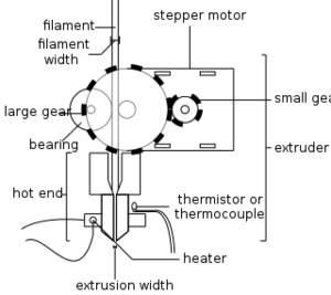
The "Hot End" is the active part of the 3D printer that melts the filament. It allows the molten plastic to exit from the small nozzle to form a thin and tacky bead of plastic that will adhere to the material it is laid on. The first RepRap hot end was made of brass. Researchers have also made hot ends from glass or aluminium. The hot end consists of a melting zone or chamber with two holes. The cold end forces the filament into the hot end -- into the heating chamber of the hot end -- through one hole. The molten plastic exits the heating chamber through the other hole at the tip. The hole in the tip (nozzle) has a diameter of between 0.3mm and 1.0mm with typical size of 0.5mm with present generation extruders. Outside the tip of the barrel is a heating means, either a wire element or a standard wire wound resistor. The heat required is of the order of 20W with typical temperatures around 150 to 250 degrees Centigrade. For feedback control of the nozzle temperature, a thermistor is usually attached close to the nozzle, though a thermocouple may serve with suitable control hardware. High temperature materials are needed here. These include metals, cements and glues, glass and mineral fibre materials, PEEK, PTFE and Kapton tape.
mount to rest of machine
The ways extruders are mounted on the rest of the machine have evolved over time into informal mounting standards. These informal standards include the Vertical X Axis Standard, the Quick-fit extruder mount, the OpenX mount, the Quick change X Carriage, etc. Such de-facto standards allows new extruder designs to be tested on existing printer frames, and new printer frame designs to use existing extruders. (Does the "greg-adapter.scad" adapter in the Prusa i3 Build Manual let me mount an OpenX extruder on a Vertical X Axis machine?)
Such standardization accelerates RepRap improvements (as described in Combinatorics Problem) by making it easier to make quick, fair comparisons between various incremental improvement ideas by swapping out just the part that's different and keeping the rest of the machinery the same. Especially when such standards support quick-change back-and-forth testing.
categorizing extruders on the wiki
Add extruders to this "extruders" category by adding {{tag|extruders}} anywhere on the wiki page about that extruder (typically in the "categories" section of the development template).
Also add the appropriate sub-category(s) --
{{tag|Cold End}} or
{{tag|Hot End}} or
{{tag|Paste Extruders}} or
etc.
-- in the same section of that wiki page.
- Can we come up with an idealized model of what *should* happen in the extruder independent of how it is implemented? RepRap forums: "What would be the ideal (theoretical) hotend/extruder combo?"
A Bit of Background
This HotEnd was developed after struggling with the fact that in Argentina (were I live) PEEK is very hard to come by, very expensive and a controlled material (since it can be used to manufacture guns).
Therefore, I went and designed a PEEK-free HotEnd.
Since PTFE is available and fairly cheap, I started to work on building a HotEnd based on that insulation.
PTFE is easy to work with, threads don't last much and are quite fragile, to solve this I went on and designed a "contained" PTFE insulation.
I took some ideas from the Budaschnozzle (which I tried, unsuccessfully, to build replacing PEEK with PTFE)
I'm a Hobbyist Lathe operator, so a lot is done on my lathe. That's a lot of help and makes this cheap.
I've used this HotEnd for at least 3 months now, and around 13 Kg of filament have gone through it. Normally I print with 0.5 mm nozzles at 40 mm/sec and at 230 - 245 ºC.
I Hope some people out there find it useful.
Gustavo "Crispy" Blanco
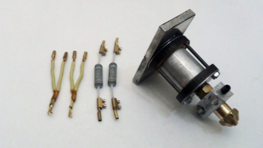
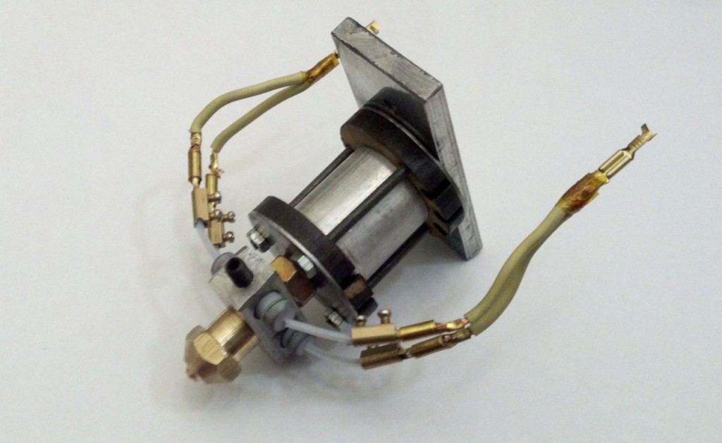
The Crispy HotEnd
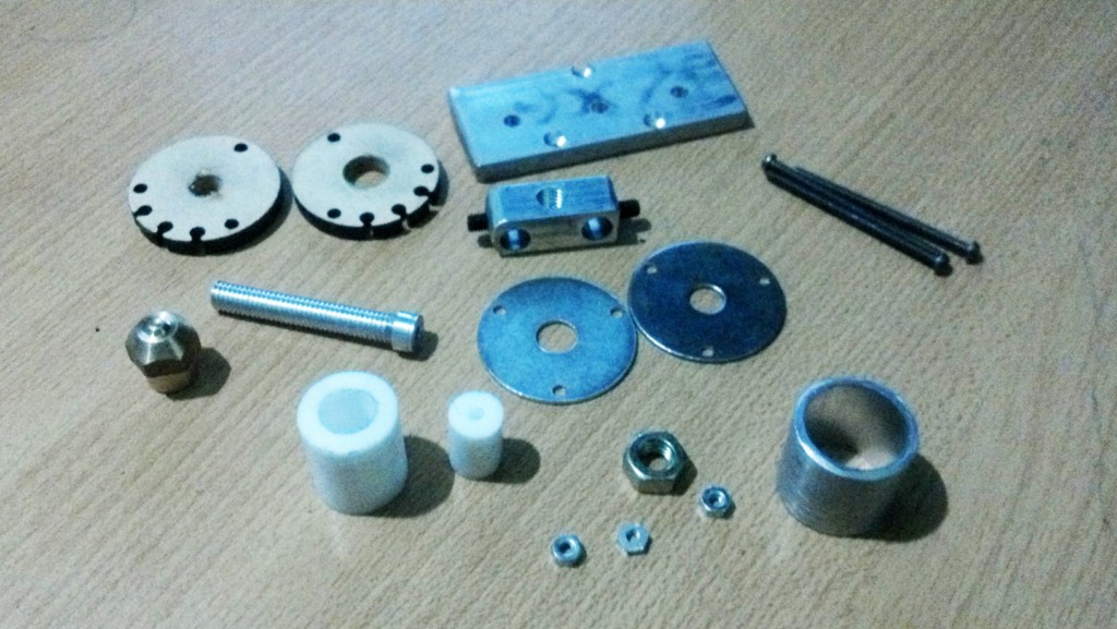
The HotEnd Disassembled
BOM (Build of Materials)
The Built
Tipically I start with the Barrel.
It's a 50mm 12mm Aluminum round bar which it turn to 8mm in diameter for 45mm, and make those 45 mm a 8x1.25 Thread.
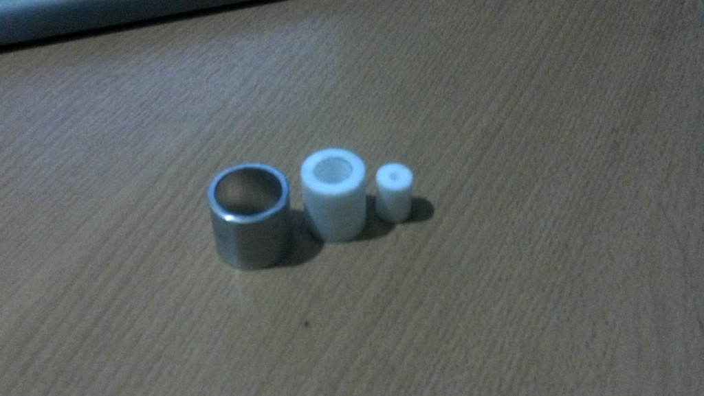
Next, I take a piece of 1" (or 25mm) Aluminum Pipe and cut a 25mm long section.
On the Lathe and with a piece o 25mm PTFE, turn it so you can fill the pipe (try to get it tight).
With a 6.75mm Drill bit, drill the PTFE (at least 30mm deep).
Then with a 12mm Drill bit, drill 18mm into the PTFE.
Now take the 12mm PTFE and brill a 3.2 hole, drill it all the way.
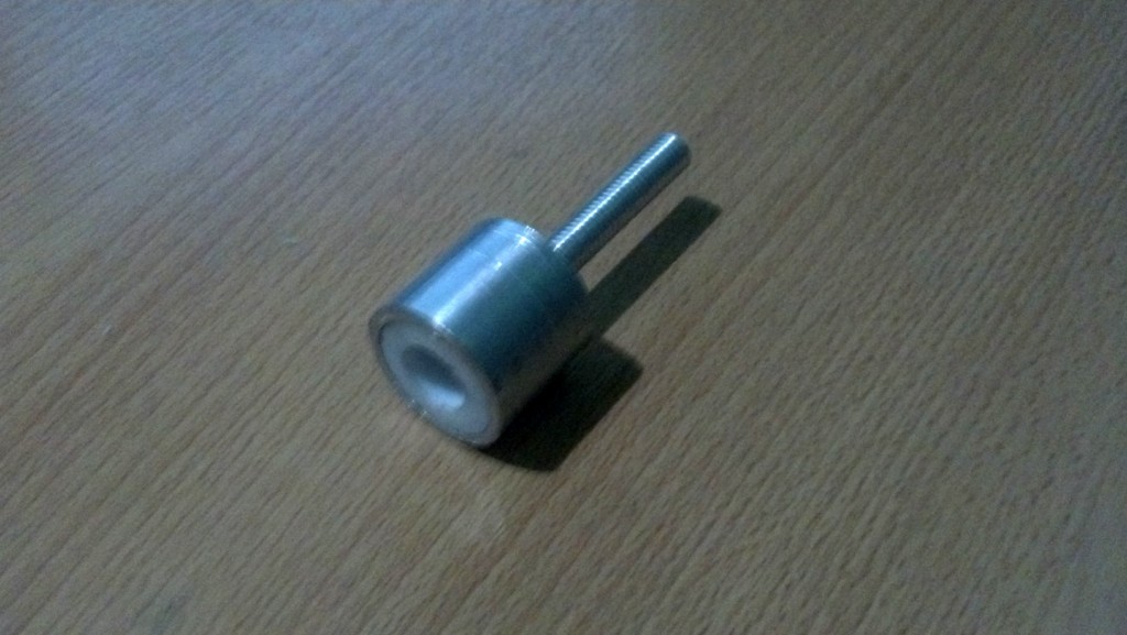
Now, insert the Barrel into the large PTFE section, using the largest hole, and screw it tight.
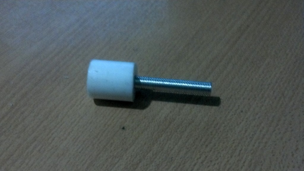
And the small PTFE to enclose the barrel.
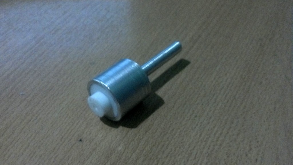
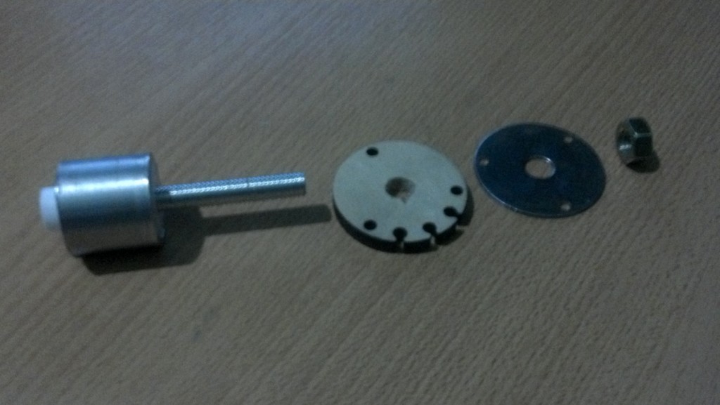
Complete the Mid Assembly by adding the parts in order.
To make these parts I've used the plans for the Budaschnozzle.
Check that the holes are aligned.
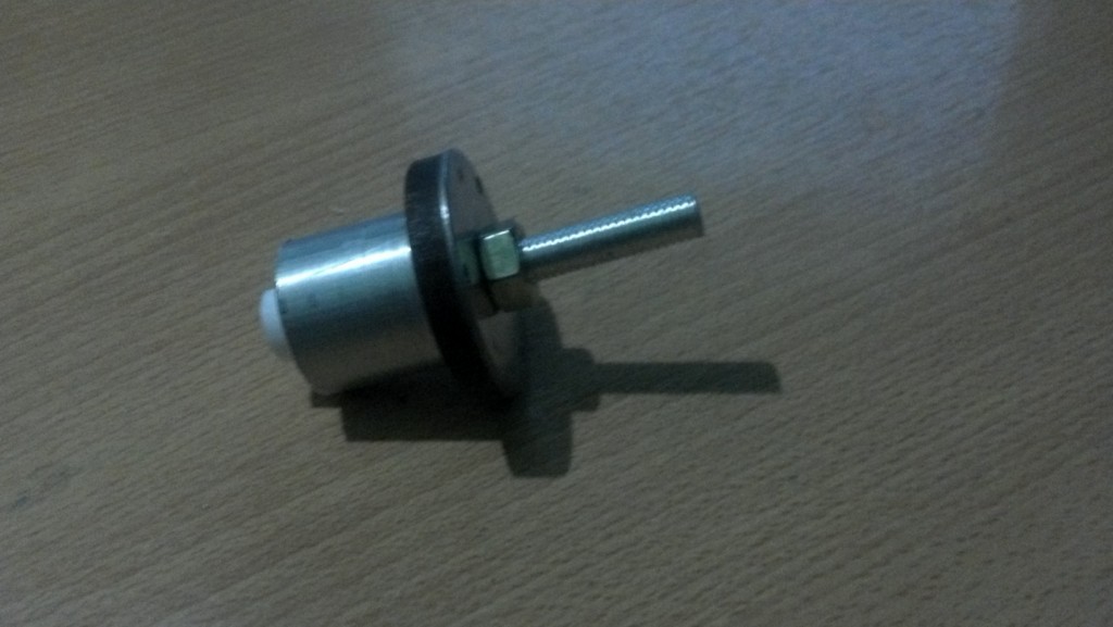
Now to Finish he Bottom Section, add the Heater Block and Nozzle
Notice the Heater Block has a 3mm hole drilled in the center for the thermistor.
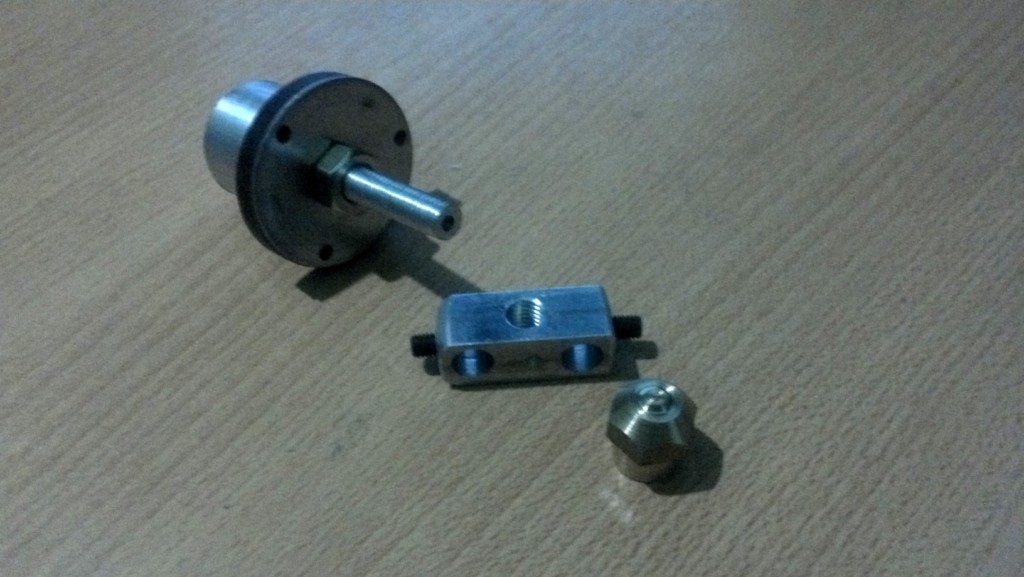
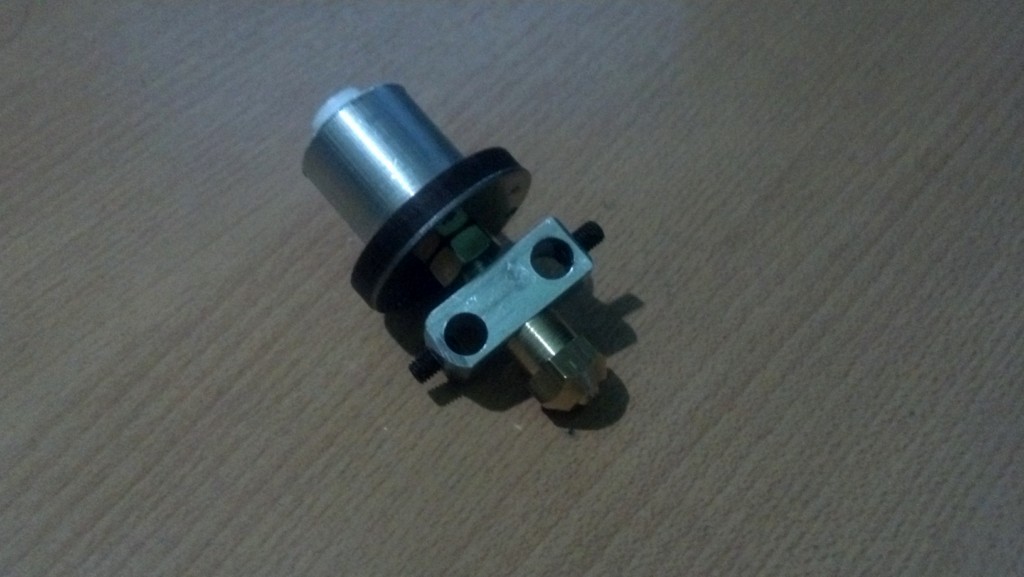
The Top Needs to be finished as in the picture
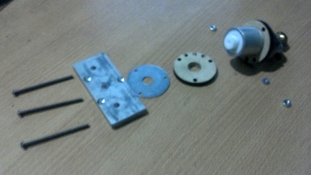
To finish the assembly, add 2 resistors and 2 Y shaped Cables to connect the Resistors in parallel.
