Duet Wiring
Contents
PWM MosFET control
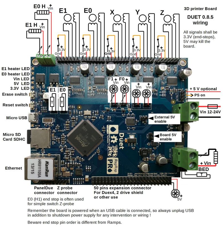
All power element which are controlled are connected to PWM controlled MosFETs which drain current to the ground ('sinking' connections). These sinking lines are indicated by an arrow. PWM frequency varies depending the application and is user adjustable for controlled fans. MosFET may fail and stay permanently conductive, in this case the connected element will go full power with the only possibility to stop being to shutdown the power supply, which is only possible if the Power Supply could be stopped via the PS-on signal. See Safety page.
Duet 0.8.5
Main wiring
All positive fan pins are connected to Vin.
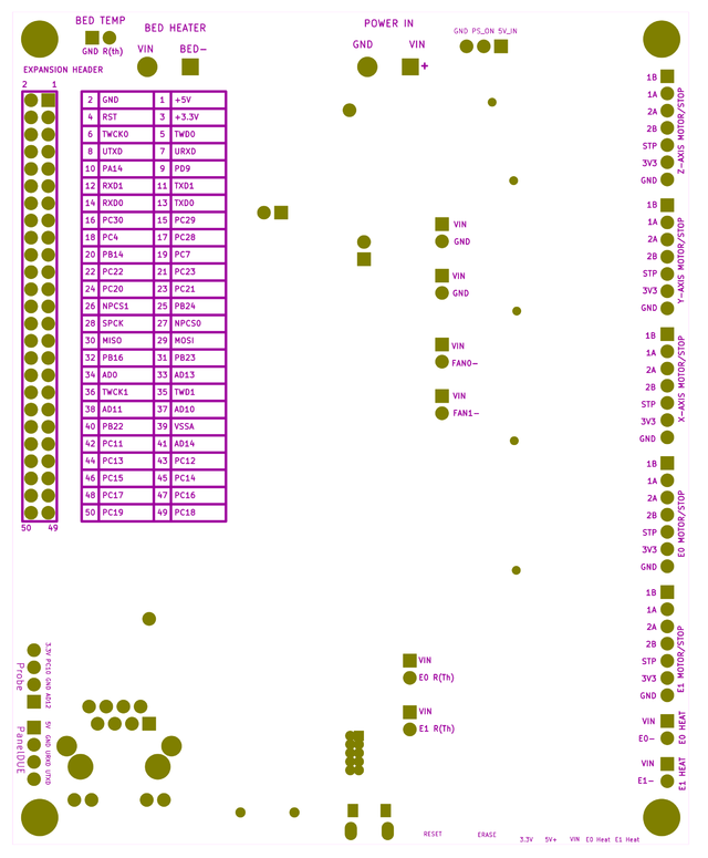
The pinouts are on the back of the board (V 0.8.5), a KiCAD export shows the back below for reference (this is the view from the bottom of the board, so is mirrored):
There is more detail on the pinouts on the Duet pinout page.
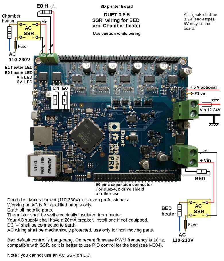
BED and chamber heater SSR wiring
Chamber heater use E1 output and thermistor input.
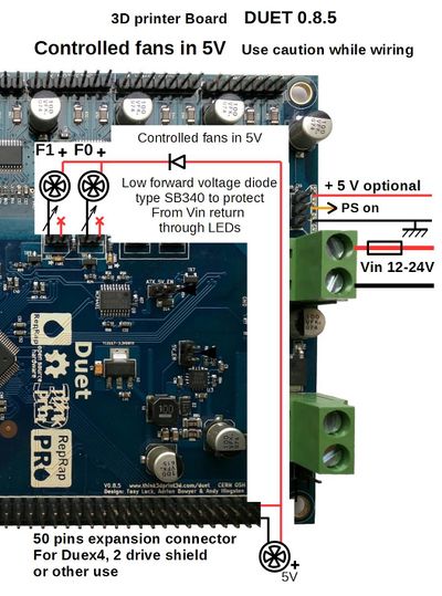
5V controlled fan
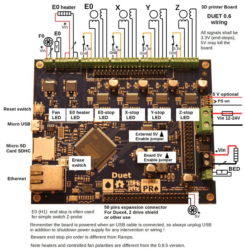
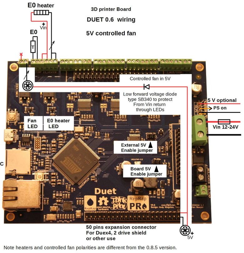
Duet 0.6
Beware of the Bed, heater and fan connector polarity, which is different from the 0.8.5 board
Main wiring
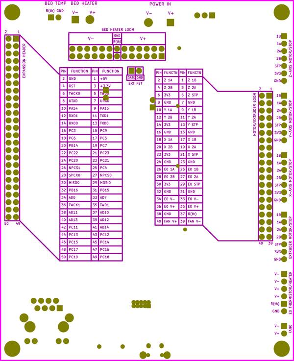
The back silkscreen on the Duet 0.6 contains further information on the pinouts, it is reproduced below
