Elegant multispline motion controller
Elegant MultiSpline Motion Controller
a rough draft by Brian Korsedal
This is a project to redo the main controller board and motion controller. I am designing a new board based on a Xilinx Spartan-6 chip (XC6SLX9-2TQG144C-ND).[1] This is a very low cost but high performance FPGA. The FPGA program will be stored in an external EEPROM. This chip is more expensive than the current IC. The chip and EEPROM should cost around $25. However the performance gains should outweigh this cost. I also think that there can be some major cost savings from mass production or merging boards together. This design will include a high speed USB 1.1 interface running at the full 12 MBPS. There will be a small amount of preprocessing which occurs on the desktop PC.
This device will not use G-code. It will use a custom language based on cubic beziers. This allows for much better description of arcs and will result in much higher quality prints with a much lower data throughput requirements. It is easy to write an application to translate from G-code to the custom bezier language. This will be the flow to support backwards compatibility.
Algorithm Explanation
The basis of the motion profile is cubic Bezier curves. These curves are easy to specify and can accurately describe toolpaths which would be a nightmare to describe in Gcode.
(insert example here)
Above is an example of a cubic Bezier. They are specified by four points. Point 1 is the start point. Point 2 is a control point. It is synonymous with the velocity vector at the start of the curve Point 1. Control point 3 is synonymous with the inverse of the velocity vector at the end of the curve. Point 4 is the end point of the curve. The magnitude of the velocity vectors is specified in terms of the curve parameter.
Bezier curves are defined by a curve parameter. This parameter ranges from 0 to 1. It describes where you are located along the curve. This parameter is usually called u. There is no simple relationship between u and S (the position in the x,y,z). This causes a big problem when plotting motion along this curve.
A key advantage of cubic beziers is that they describe jerk limited motion. The first derivative (velocity) of a cubic Bezier curve (dS/du) is a quadratic Bezier. The second derivative (acceleration) is a straight line. The third derivative (jerk) is a constant. This naturally creates the desired motion profiles while still being easy to compute. It might be possible to further simplify the computations using quadratic Beziers instead of cubic Beziers. However, I am unsure if the quadratic Beziers will describe all the required toolpaths accurately. There are also interesting papers on Biarc specifications or higher orders. This can be determined by whomever continues my work. “A good plan violently executed now is better than a perfect plan executed next week.” General George S. Patton.
As was noted earlier there is no simple relationship between u and S (position in x,y,z). This creates a large problem. The way I solve it is to use numerical integration and parallel computing. FPGA's are masters of parallel computing. Even low cost FPGA's will crush most DSP and processors in raw power. In the past FPGA's have been difficult to program. Fortunately there are new tools on the market which dramatically reduce the effort needed to program FPGA's. These new tools are based on Matlab and Simulink. They allow an exponential leap in productivity and allow engineers to keep pace with Moore's law. This design was implemented using Xilinx System Generator. This design was created from scratch in under three weeks. It is a good example of the exponential leap in productivity that these new tools create.
Matlab Code
Here is the matlab code we are going to discuss.File:EMMC5.m
This code performs all the tasks that the system will perform. In the beginning of the file there are some control points for three bezier curves. The control points are four dimensional. They have X,Y,Z and Ext components. The Ext component corresponds to the instantaneous extrude rate. It has a range from 0 to 1. O is off. 1 is fully on. All values in between are valid. This allows us to perform arcs in the extrude path which will reduce the jerkyness in the extrude profile. There are different velocity limits depending on the instantaneous extrusion rate.
The first part of the file sets up the bezier curves to be processed. It puts them into a form which is easier for the FPGA to manage. Then it calculates discontinuities at the transition points between the bezier curves. It is preferred that the curves are continuous in both the velocity and curvature, but it is not required. When there are discontinuities between curves the preprocessing will insert end and start discontinuity parameters which the rough velocity profiler will use to avoid issues in the motion profile.
The next block of code performs a first pass of numeric integration for the bezier curve. The rough velocity profile records the distance traveled along the line. This rough profile uses the curvature, velocity limit, extrusion rate, start discontinuity and stop discontinuites to calculate the maximum velocity on the curve.
This velocity profile will have very sharp transitions. Due to the nature of digital filter and CIC filters specifically we can just filter the rough velocity profile to remove these sharp transitions.
We then perform a second pass on the bezier numerical integrator to produce the actual output points. These output points are choosen so that they conform to the filtered rough velocity profile.
The FPGA will closely mirror what happens in the matlab code.
FPGA implimentation and theory
The FPGA will be split into several parts.
Pulse Probability Modulator
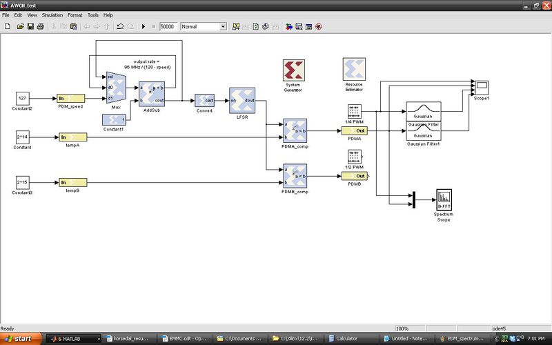
The MOSFETs for the heaters are driven by a Pulse Probability Modulator. The output of my modulator is driven by probability. There is a psuedo-random number generator in the design. It compares a this random number with the setting for the DC voltage level. This creates a random high or low at the gate of the mosfet. The probability of this output is driven by the DC voltage setting. The higher the setting inside the FPGA, the higher the FPGA will drive the gate high.
The psuedo-random number generator is a linear shift register. Theory can be found on Wikipedia. In this configuration it will generate a repeating sequence of 2^16-1 numbers. None of the numbers will be repeated in the sequence.
The update rate of the linear shift register is driven by a speed parameter. It is configured so that the update rate is equal to the FPGA clock rate divided by (128 - speed). This parameter will be determined based upon the switching speed of the MOSFET. Higher update rates on the gate will create less noise. If the setting is too high it might cause issues with heat or problems with duty cycle on the MOSFET.
The advantage of this type of modulation is a decrease in spurious noise. PWM is a square wave. This creates very high frequencies at the harmonics of the square wave.
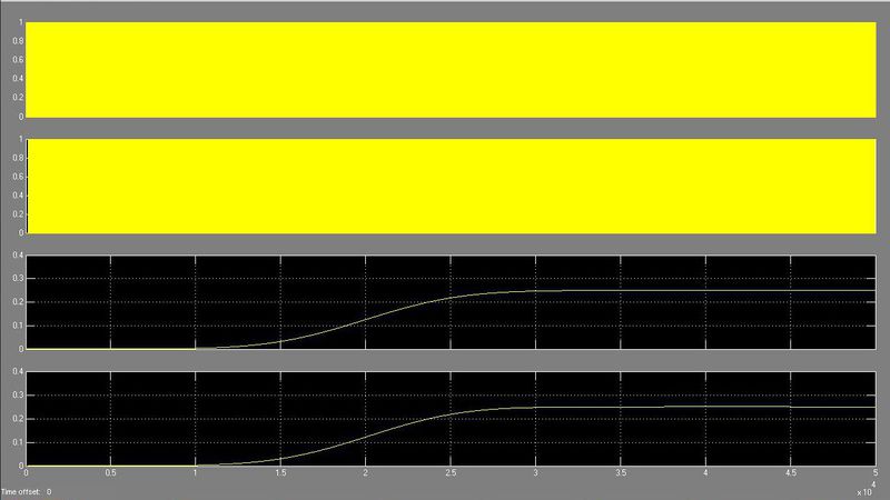
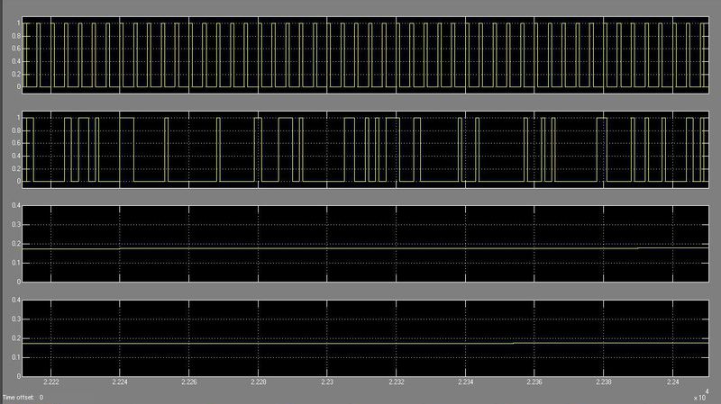
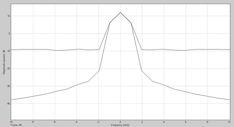
Above you can see a block diagram for the AWGN Pulse Density Modulator. These next two plots show the output of the block. The top signal is a square wave with a 25% duty cycle. The second signal is the output of the AWGN PDM with a duty cycle of 25%. The next two signals are the results of a low pass filter. The low pass filter in the real Reprap is the nicrome wire or whatever is being heated. This is a very low pass filter.
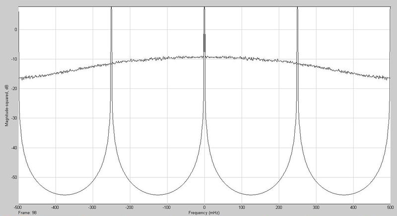
Next is a comparison of the spectrum of the two waves. They both have a sharp peak at DC showing the 25% duty cycle. The AWGN PWM drops off to a noise floor about 20 dB down from the peak. The square wave drops down sharply but then spikes dramatically at the harmonics of the square wave.
I2C Audio ADC interface
USB 1.1 interface
AB FIFO
MultiSpline Engine
