Example DIY Supports 2
|
English • العربية • български • català • čeština • Deutsch • Ελληνικά • español • فارسی • français • hrvatski • magyar • italiano • română • 日本語 • 한국어 • lietuvių • Nederlands • norsk • polski • português • русский • Türkçe • українська • 中文(中国大陆) • 中文(台灣) • עברית • azərbaycanca • |
Width of DIY Supports
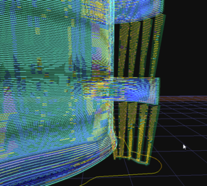
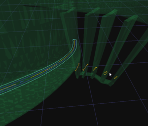
One of the complications with DIY supports is getting the widths correct. Slicers will generally have problems with this, in my experience. The only solution I know of is to make the widths a bit larger than the planned extrusion width, and then go back and forth between the modeling and the slicing. My final extrusion width is .45mm in KISSlicer, depicted in the 2nd and 3rd image, so I began with supports roughly .5mm wide, and thickened them as needed.
Two primary complications occur: 1. The thin walls of the support result in gaps/holes, as the slicers often disregard parts that it considers too thin to print. 2. The support's shape is created with multiple paths -- sometimes this might be desirable, but for me that's rare. The closeup (Image 3) shows the I-shaped patterns, as the slicer perhaps attempts to make the rectanglar cross-sections have corners. It also shows the presence of rectangular paths. I should point out that, as of the time of this writing, I did not yet try printing this particular model with DIY supports (but I did, with generated supports). Nevertheless, I believe it is at the point where it would print well.
File Format Limitations
The standard model format (.STL) only provides a mesh to the processing software -- there is no way to give additional information about an object or its parts to a slicer. This means you can't say "this 'thin wall' can be generated as single continuous paths". When a slicer generates supports, itself, it can create nice simple paths for supports, but when making your own supports, as objects, there can be some amount of experimentation necessary to get the extrusions/gcode to an acceptable state. In the 3rd image, again, the closeup shows the I-shape of the thinnest supports, and the rectangular-ish paths created for those that were perhaps a bit thicker. It would be nice to provide object-information to a slicer, but at present, at least with STL, that is not an option.
Control Over Attachment Points
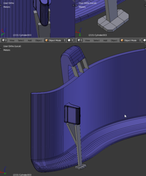
It is worthwhile to note that, while these images show the control one can have over exactly where the supports attach, another option is more advanced support generation, such as Autodesk's MeshMixer, which can automatically generate supports which are efficient in material use and printing time. It is, unfortunately, presently limited (I believe, as of March 2015 or so) only to tree-like structures of supports. You then output this generated object, plus its supports, as an object, and slice it in your slicer of choice. The minimal nature and configurable locations of attachment is a nice feature, however, since slicing software nearly all seem to generate only vertical supports at present.
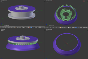
The last image is of a replacement part for an "inexpensive" air-compressor valve. The model demonstrates a different type of support -- a ring used to support the top, while spreading outwards so the base of the support doesn't touch the object. On top of the ring-support are small fins which allow the object's overhang peripheral paths to be more-readily separated from the supports. The valve is 2.70cm across, and 3.0460cm with the support-ring. This one I did print, and it's in the air-compressor now.


