Extruder Controller 2 0
Contents
- 1 Extruder Controller v2.0
- 1.1 Overview
- 1.2 Get It!
- 1.3 Files
- 1.4 Interface
- 1.5 Circuit Board
- 1.6 Components
- 1.7 Build Process
Extruder Controller v2.0
Overview
<div class="thumb tright"></div>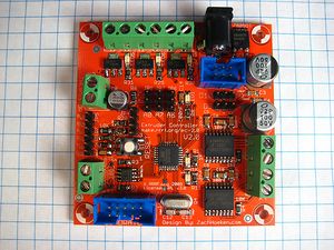
This board is a combination of the PWM Driver Board, DC Motor Driver Board, Temperature Sensor Board, RS485 comms, and an Arduino! All on one board. It has screw terminals for easy hookup, as well as a power jack for power and an IDC header for the rotary encoder. Its an all-in-one solution for controlling an extruder.
Some highlights:
- Onboard atmega168 - program it just like an Arduino because it is an Arduino.
- 3 x MOSFET drivers for controlling up to 14A @ 12V. Perfect for heaters, fans, solenoids, etc.
- 2 x H-Bridges capable of up to 2A each. Control 2 motors, or control one stepper motor.
- A temperature sensor circuit for reading the standard 100K thermistor.
- RS485 connection for noise-free communications with the motherboard.
- IDC header for connecting a Magnetic Rotary Encoder.
- ICSP header for manual programming.
- It mounts directly to the Pinch Wheel Extruder!
Get It!
Fully Assembled
- Coming soon!
Full Kit
- Coming soon!
Raw Components
Files
<div class="thumb tright"></div>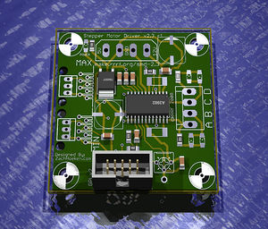
You can download the release file from SourceForge that has a bunch of helpful files for this board. It contains:
- GERBER files for getting it manufactured
- PDF files of the schematic, copper layers, and silkscreen
- Eagle source files for modification
- 3D rendered image as well as POVRay scene file
- exerciser code to test your board.
Schematic
<div class="thumb tright"></div>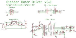
Interface
H-Bridges
MOSFETS
Thermistor
RS485
Quadrature
DC Power Jack
Serial Header
Circuit Board
<div class="thumb tright"></div>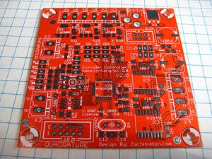
You can either buy this PCB from a supplier, or you can make your own. The image above shows the professionally manufactured PCB ready for soldering.
Components
<div class="thumb tright"></div>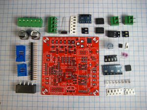
<iframe src="http://parts.reprap.org/embed/module/Extruder+Controller+v2.0" width="800" height="700" frameborder="0">Visit http://parts.reprap.org/embed/module/Extruder+Controller+v2.0</iframe>
Build Process
- You'll need a soldering toolkit to do most of this.
- You'll also need a SMT soldering toolkit to construct this board.
This board contains surface mount parts. Trust me when I tell you that it is really, really, really easy! The hardest part about SMT soldering is getting over your fear and staying calm. I've shown complete beginners how to do it, and they had no problems.
There are four parts to building a surface mount board using the Hotplate Reflow Technique:
- Apply solder paste to every exposed SMD pad
- Place each SMD component on its appropriate pad
- Place populated board on a cold hotplate. Turn hotplate on. Board solders itself!
- Solder in remaining through hole components.
Apply Solder Paste
<div class="thumb tright"></div>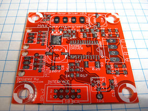
Okay, so this part is pretty easy: get your solder paste syringe and start applying solder paste to every SMD pad. I like to use a squeeze/tap method. That is, I squeeze a bit of solder paste out, then tap the place where it goes, rinse and repeat for every exposed pad. Do not put solder paste on pads with holes in them. You'll solder those in step #4.
Place Components
<div class="thumb tright"></div>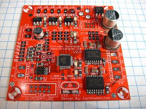
This is probably the trickiest part. Its easiest with tweezers and some sort of magnification. A bit of patience and you'll get it no problem. Since nothing gets soldered yet, you can easily try and try again if you mess up.
TODO: Show pictures of each individual component placement.
Hot Plate Reflow
<div class="thumb tright"></div>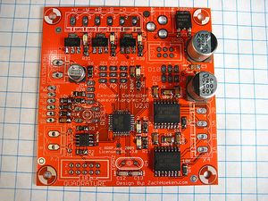
I prefer to start with the hotplate off. I burned a few boards one time by putting them on when it was already hot. Instead, carefully place the board on the cold hotplate, thn turn the heat up to a low temperature. Wait a few minutes for things to get cooking, and you'll see the small components begin to 'pop' as the solder goes molten. Keep an eye out for components that stick together. If that happens, simply nudge them apart. Wait until you see the largest component leads go silver. Usually the capacitors are the last to go.
Once they have soldered, simply turn the hotplate off and let it cool down.
Solder Through Hole Components
16Mhz Crystal
<div class="thumb tright"></div>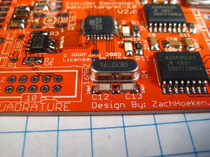
This can be inserted in any orientation. Make sure you trim the legs afterwards.
Quadrature Header
<div class="thumb tright"></div>
There is a notch on the part that lines up with the 'notch' on the silkscreen. It should face the outside of the board. Make sure to solder it in the proper orientation.
ICSP Header
<div class="thumb tright"></div>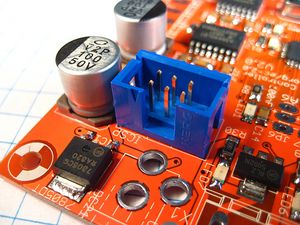
There is a notch on the part that lines up with the 'notch' on the silkscreen. It should face the outside of the board. Make sure to solder it in the proper orientation.
Thermistor / RS485 Screw Terminals
<div class="thumb tright"></div>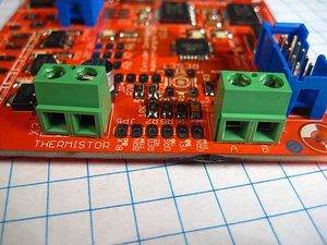
These are the same component. Make sure you solder them with the openings facing the outside of the board.
MOSFET Terminals
<div class="thumb tright"></div>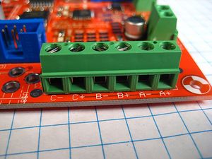
These are the screw terminals for the MOSFETS. Make sure you solder them with the openings facing the outside of the board.
H-Bridge Terminals
<div class="thumb tright"></div>These are the screw terminals for the H-Bridges. Make sure you solder them with the openings facing the outside of the board.
Servo Headers
<div class="thumb tright"></div>These are the headers for attaching servo motors. Its easiest to solder them in if you put the long ends into an IDC connector and use that to hold them in. It can be a bit tricky though.
Serial Headers
<div class="thumb tright"></div>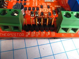
These are the headers for the serial connection. Its easiest to solder them in if you put the long ends into an IDC connector and use that to hold them in. It can be a bit tricky though.
I2C Header
<div class="thumb tright"></div>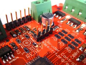
These are the headers for the I2C bus. Its easiest to solder them in if you put the long ends into an IDC connector and use that to hold them in. It can be a bit tricky though.
Reset Button
<div class="thumb tright"></div>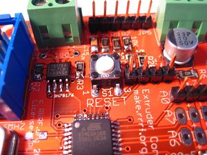
The button will snap into place. Solder it in and you're good.
Extra Headers
<div class="thumb tright"></div>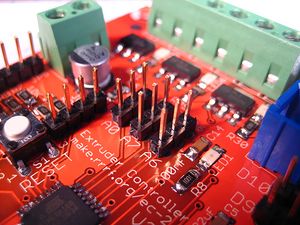
These are extra headers for the unused pins. Its easiest to solder them in if you put the long ends into an IDC connector and use that to hold them in. It can be a bit tricky though.
DC Power Jack
<div class="thumb tright"></div>This is a power jack for powering the board. It will only solder in one direction, so solder it in and you're good to go.