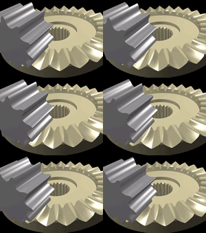
Gear design
Gear Design Basics
If you're an engineer, this is probably old hat - but read it anyway so you can correct my mitsakes. Gears are generally round, with teeth. The number of teeth and their shape are more important than is initally apparent. They need to mesh, and so need to be the same size. The incoming gear teeth must contact at the right place, and only at the right place - which is why they're a funny shape and not square or little triangles.
The tip of the gear teeth are not supposed to go all the way down into the opposing trough. If that happens the next incoming tooth tip smacks into the top of the opposing tooth. Contact between teeth is notionally along a point just over half way (typically a 1:1.25 split) up the teeth, and this is called the 'Pitch Line'. The bit above the pitch line is called the 'Addendum', the bit below it the 'Dedendum'. The angle of tilt on the faces of the teeth is called the 'Pressure Angle' and is normally about 20 degrees.
The forces between the contacting teeth have to be even and consistent, or vibration builds up. So does noise and wear. These problems are made worse by teeth flexing around, so with a relativley soft plastic we're going to have interesting problems.
To provide mechanical advantage, contacting gears have different numbers of teeth. A little gear driving a big gear will increase the power and slow down the speed of rotation. Gears typically have prime or at least odd or non-multiple numbers of teeth. This is so that the same teeth do not always press against one another, so distributing wear, dirt, oil and squashed fingers etc. evenly across all gear teeth involved.
FDM Restrictions
Gears made from ABS or Polymorph need to be sturdily constructed in order to survive. Little pointy bits will soon be broken off when the mechanism (inevitably) jams. Wear & tear is a fact of life, and so plenty of extra material is needed. In short, your gears will be chunky and inaccurate.
We make the gears fairly thick, as the larger contact area lowers the contact pressure and hence the wear. We use smooth curves rather than angular jumps, partly because the FDM machine can't be sufficiently accurate, and partly because they'd introduce points of wear.
To lower the mass of the plastic used, we put strategic cut-outs in the gear to create spokes. Everything is still kept nice and chunky to avoid flexing. Flexing leads to wear and noise.
Finally, we need to attach some of the gears to a shaft. As the plastic is not that strong, this needs big, chunky collars to hold big grub screws, or in the case of this example a recess to hold a nut.
Actually Designing Gears In ArtOfIllusion
AoI has a "Cog" script, which I (VikOlliver) adapted from a "Star" script kindly created for me by Francois Guillet.
To load it, go to AoI's "Tools" menu, and select the Scripts & Plugins Manager. Under the "Install" tab are many useful bits. In Scripts/Tools you'll find a "Cog" script. If it's not there you may have installed it already.
To Be Continued..
References
Basic Gear Formulas http://www.pic-design.com/tech/gear_form/gear_form1.htm
-- Main.VikOlliver - 14 Nov 2005
