Geared extruder nozzle
Release status: working
| Description | Geared-extruder PTFE and brass nozzle
|
| License | GPL
|
| Author | |
| Contributors | |
| Based-on | |
| Categories | |
| CAD Models | |
| External Link |
Introduction
This is a very reliable design. I have used it to reprap all the parts for five complete Mendels and counting, and it has required no attention. It has three main parts: a PTFE insulator that separates the hot end from the RepRap machine, a heated brass nozzle, and a PEEK support that holds the nozzle in place.
All the forces in the design are taken by the PEEK and two threaded rods. This means that the PTFE is not under tension. The PTFE is also inside the brass nozzle, which means that internal extrude pressure tends to seal the join between the two, rather than opening it up.
All the files for this design are in mendel/mechanics/solid-models/extruders/geared-pinch-wheel.
The reinforcement and the mounting holes needed for this design are in the standard reprapped parts for the extruder.
Machined parts
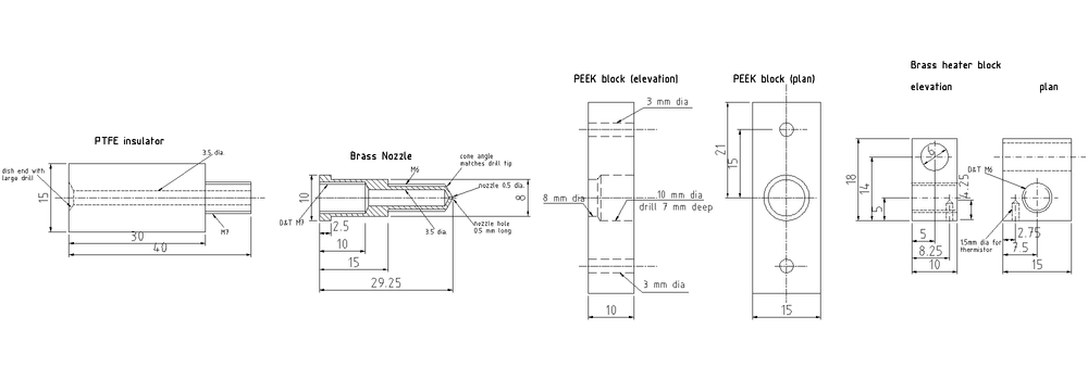
Here is the drawing for the three machined parts:
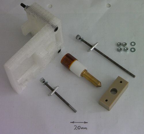
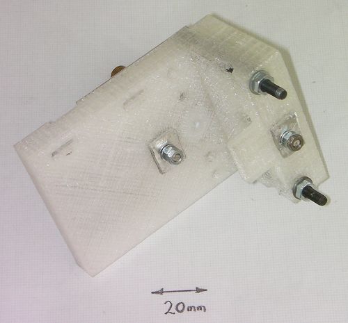
And here are the parts themselves together with the two reprapped extruder components to which they attach:
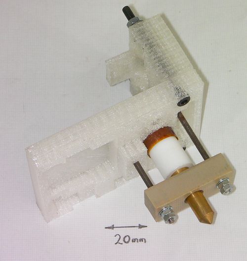
The brass nozzle has been screwed onto the PTFE, and lock nuts have been assembled onto the ends of the threaded rods (see below).
Bill of materials
| no. off | part |
| 1 | brass nozzle |
| 1 | PTFE insulator |
| 1 | PEEK support |
| 92 mm | M3 threaded rod |
| 58 mm | M3 threaded rod |
| 8 | M3 nuts |
| 4 | M3 washers |
| 2 | 10mm square scrap al. sheet |
| ~200 mm | Kapton tape |
| ~100 mm | PTFE tape |
The PEEK support block (being small) is not at all expensive. But suppliers won't sell small quantities of blank 10mm plate. This is a very good reason to crowd-source: buy a 10mm plate (try here or here); cut off what you need; cut the rest into blanks and sell them for a reasonable price on Ebay to other reprappers...
Construction
The base and the driven-gear holder of the extruder have to be assembled together before this nozzle can be attached. Put them together with two M4 bolts, two washers and two nuts.
Machine the PTFE, the brass and the PEEK.
Making the brass nozzle is simplest if you drill the 0.5mm nozzle hole 4 or 5 mm deep in the end before you turn down the cone, then drill the 3.5 mm hole from the other end.
Cut the M3 rods to length.
Cut two pieces of aluminium sheet about 10 mm square and drill two 3 mm holes in the middle of them. These will spread the load from the tension in the threaded rods over the plastic parts of the reprapped extruder.
Wrap Kapton tape round the head of the PTFE insulator until it is fat enough to fit snugly in the hole in the extruder body. This hole is deliberately over-sized to allow alternative designs to be epoxied in here.
Wrap several winds of PTFE tape round the M7 threads on the PTFE, then screw the brass nozzle tightly onto those threads and that tape.
Important step: Screwing the brass and PTFE together will slightly compress the 3.5 mm hole down the middle of the PTFE. Keeping the pointed end of the nozzle pointing upwards, twist a 3.5 mm drill bit by hand up the hole to enlarge it back to the correct size. Pull out any PTFE swarf created and, if you have access to an air line, blow through from the nozzle end. You are keeping the nozzle pointing upwards so that gravity is tending to clear out the swarf. It is important not to leave any lose pieces of PTFE in there as these will block the nozzle.
Put two nuts on the ends of the M3 rods and lock them together. This effectively makes two very long M3 screws.
Put a washer and a 10mm aluminium plate on each one and put it through the two holes in the extruder body.
Push the Kapton-expanded end of the PTFE into the hole in the extruder.
Put the PEEK block on the nozzle and the two M3 rods. The smaller 8mm end of the central hole should be uppermost and should bear against the flange on the brass nozzle. The larger 10 mm hole in the PEEK is to reduce thermal conductivity between the brass and the PEEK, to keep everything cool.
Put M3 washers on the M3 rods and tighten two M3 nuts onto the PEEK to hold the whole device together. Don't over tighten these - things need to be firm; that's all. Finally, put two more M3 nuts on and lock them hard against the nuts you just tightened (without tightening them any further). You need lock nuts to hold the whole thing together and to stop it vibrating lose. Nylock nuts won't do - the bottom end gets too hot for the nylon.
See also: Best Compromise Nozzle
