Geared extruder nozzle
Release status: working
| Description | Geared-extruder PTFE and brass nozzle
|
| License | GPL
|
| Author | |
| Contributors | |
| Based-on | |
| Categories | |
| CAD Models | |
| External Link |
Contents
Introduction
This is a very reliable design. I have used it to reprap all the parts for five complete Mendels and counting, and it has required no attention. It has four main parts: a PTFE insulator that separates the hot end from the RepRap machine, a brass nozzle, a brass heater block, and a PEEK support that holds the nozzle in place.
All the forces in the design are taken by the PEEK and two threaded rods. This means that the PTFE is not under tension. The PTFE is also inside the brass nozzle, which means that internal extrude pressure tends to seal the join between the two, rather than opening it up.
All the files for this design are in mendel/mechanics/solid-models/extruders/geared-pinch-wheel.
The reinforcement and the mounting holes needed for this design are in the standard reprapped parts for the extruder.
Machined parts
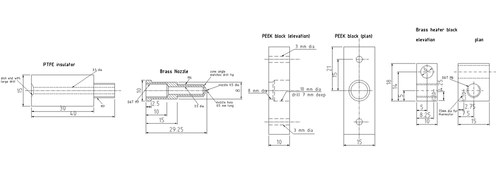
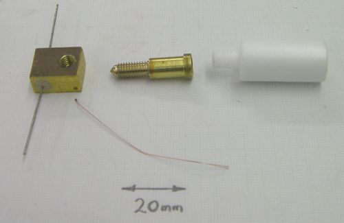
Here is the drawing for the four machined parts:
Though it says brass, you can make the nozzle from brass or aluminium. Both should work well.
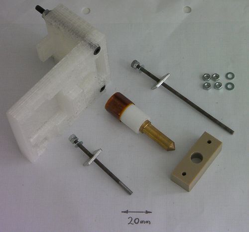
And here are the parts themselves together with the two reprapped extruder components to which they attach:
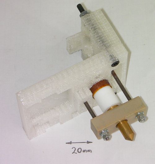
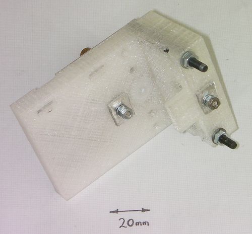
The brass nozzle has been screwed onto the PTFE, and lock nuts have been assembled onto the ends of the threaded rods (see below).
Bill of materials
| no. off | part |
| 1 | brass nozzle |
| 1 | PTFE insulator |
| 1 | PEEK support |
| 92 mm | M3 threaded rod |
| 58 mm | M3 threaded rod |
| 8 | M3 nuts |
| 4 | M3 washers |
| 2 | 10mm square scrap al. sheet |
| ~200 mm | Kapton tape |
| ~100 mm | PTFE tape |
The PEEK support block (being small) is not at all expensive. But suppliers won't sell small quantities of blank 10mm plate. This is a very good reason to crowd-source: buy a 10mm plate (try here or here); cut off what you need; cut the rest into blanks and sell them for a reasonable price on Ebay to other reprappers... Another solution is to use round PEEK Rod as described here
Construction
The base and the driven-gear holder of the extruder have to be assembled together before this nozzle can be attached. Put them together with two M4 bolts, two washers and two nuts.
Machine the PTFE, the brass and the PEEK.
Making the brass nozzle is simplest if you drill the 0.5mm nozzle hole 4 or 5 mm deep in the end before you turn down the cone, then drill the 3.5 mm hole from the other end.
Cut the M3 rods to length.
Cut two pieces of aluminium sheet about 10 mm square and drill two 3 mm holes in the middle of them. These will spread the load from the tension in the threaded rods over the plastic parts of the reprapped extruder.
Wrap Kapton tape round the head of the PTFE insulator until it is fat enough to fit snugly in the hole in the extruder body. This hole is deliberately over-sized to allow alternative designs to be epoxied in here.
Wrap several winds of PTFE tape round the M7 threads on the PTFE, then screw the brass nozzle tightly onto those threads and that tape.
Important step: Screwing the brass and PTFE together will slightly compress the 3.5 mm hole down the middle of the PTFE. Keeping the pointed end of the nozzle pointing upwards, twist a 3.5 mm drill bit by hand up the hole to enlarge it back to the correct size. Pull out any PTFE swarf created and, if you have access to an air line, blow through from the nozzle end. You are keeping the nozzle pointing upwards so that gravity is tending to clear out the swarf. It is important not to leave any lose pieces of PTFE in there as these will block the nozzle.
Put two nuts on the ends of the M3 rods and lock them together. This effectively makes two very long M3 screws.
Put a washer and a 10mm aluminium plate on each one and put it through the two holes in the extruder body.
Push the Kapton-expanded end of the PTFE into the hole in the extruder.
Put the PEEK block on the nozzle and the two M3 rods. The smaller 8mm end of the central hole should be uppermost and should bear against the flange on the brass nozzle. The larger 10 mm hole in the PEEK is to reduce thermal conductivity between the brass and the PEEK, to keep everything cool.
Put M3 washers on the M3 rods and tighten two M3 nuts onto the PEEK to hold the whole device together. Don't over tighten these - things need to be firm; that's all. Finally, put two more M3 nuts on and lock them hard against the nuts you just tightened (without tightening them any further). You need lock nuts to hold the whole thing together and to stop it vibrating lose. Nylock nuts won't do - the bottom end gets too hot for the nylon.
Variations on this design
This is the place to add variations and improvements to this design.
Block Heater
Thanks to Nophead...
If you can make one of these, it is much simpler and more reliable than using nichrome wire as a heater. If you are going to use this design, make its block before you make the nozzle above. That will allow you to get the measurements right.
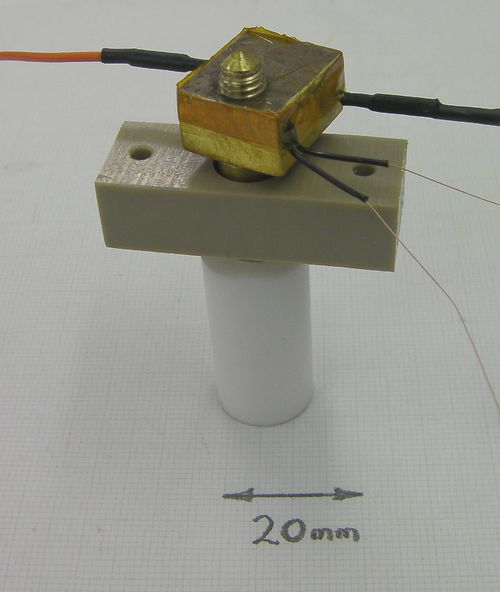
This device uses a resistor embedded in a metal block to heat the extruder nozzle. The resistor is the at the bottom of the picture. The block has a thermistor embedded in it to measure its temperature - those are the fine wires extending from it.
The precise dimensions of this device will depend on the heating resistor you use, so get that first and measure it. You need a 6.8 ohm wire-wound resistor. Ideally get a vitreous one like this, though I have used silicone-coated ones like this quite satisfactorily.
Both of those have a power rating of about 3 watts. You are going to run them at about 20 watts, but don't worry - the power rating given is for when they run in air and you are going to run them in a metal block which will take the heat away. They also have a top temperature of 200oC and you are going to run them a few tens of degrees hotter. Again, don't worry - the temperature limit is that beyond which you can no longer rely on the accuracy of the resistance; if you run them a bit hotter it won't damage them.
Start with the heating block. This needs to be about 12mm x 20mm x length-of-resistor, and can be made from brass or aluminium. A constraint on length is that the device has to fit between the bottom of the PEEK support bracket (the brown block with three holes at the top of the picture) and the end of the nozzle. Most importantly, one of the resistor's leads will poke out of the bottom of the device adding a few millimeters, especially when it has an insulating sleeve on it. The sum of all these lengths must be such that the lowest point on the device is higher than the tip of the nozzle, otherwise it will scrape on the object that RepRap is building.
If you are having trouble getting enough room, consider turning the resistor through a right-angle, so its axis is horizontal when the nozzle is vertical.
At one end of the block, drill and tap and M6 through hole. At the other, drill a hole slightly larger than the diameter of the resistor. Finally drill a small hole to put the thermistor in. I used this thermistor, which needed a 1.5 mm diameter hole. Put the thermistor at the extruder end of the block away from the resistor, and at the bottom nozzle end. Make the hole for it about five mm deep.
As you can see, the brass nozzle has been turned down for part of its length and threaded with an M6 thread. The block screws onto this. When you make the nozzle, turn its end down to 6 mm and run a die down it to cut the thread after you have drilled the fine nozzle hole in the end and made the cone, but before you part the nozzle off from the brass rod from which you are making it.
Fit the resistor into the block. I used fire cement diluted with a little water to hold it in place. You could also use a high-temperature glue, such as JB Weld. If you use the fire cement, place the block on a cooker plate on its lowest setting for about 15 minutes to set. Glue will probably take longer.
Crimp leads onto the ends of the resistor using bootlace ferrules or similar. Don't solder them - they will get too hot for solder. Insulate the join with heat-shrink sleeving.
I insulated the thermistor leads with sleeving taken from some PTFE-insulated instrumentation wire. Alternatively, insulate the thermistor leads with PTFE plumber's tape - fiddly, but doable.
Place the thermistor in its hole and secure it with Kapton tape.
Screw the block onto the nozzle tight, then screw the nozzle onto its PTFE insulator. Don't forget to clean out the central hole down which the filament will run in both as described in the main section above.
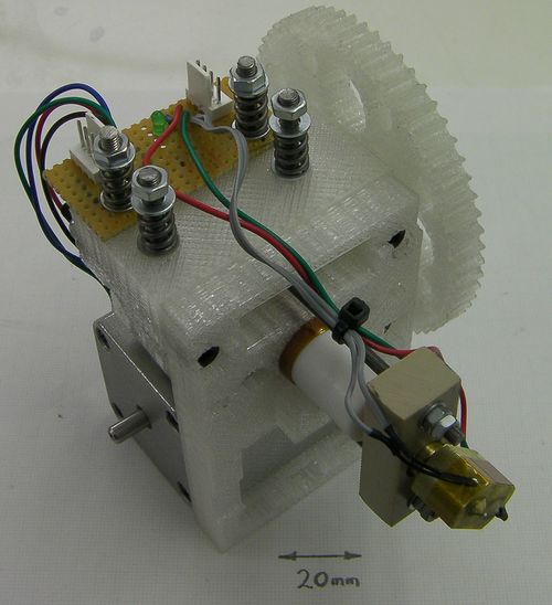
This shows the device in place on the extruder. Turn it so that it doesn't prevent you doing up the M3 nuts that hold the extruder together, but also so it doesn't stick out at right angles. That will make it easier to attach the extruder to RepRap's X carriage.
If you are used to running a nozzle with the thermistor attached to its surface, you will have to set temperatures higher for this design. For example, with a surface-thermistor nozzle I extrude PLA at 205oC, but with this device I use 240oC. That is beacuse the buried thermistor measures the core temperature, which is hotter than the surface temperature. The block and nozzle combined have a bigger thermal inertia than the nozzle on its own, so this design will take a little longer to heat up. It also means that it can be heated using simple bang-bang thermostat control; there's no need for PID control.
See also: Extruder Nozzle Variations
