Gears:Simultaneous Meshing with Rack
Release status: Working
| Description | A method for calculating gear center distances
|
| License | unknown
|
| Author | |
| Contributors | |
| Based-on | |
| Categories | |
| CAD Models | |
| External Link |
Introduction
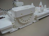
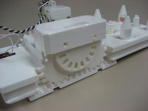
Recently, Peter posted this great prototype of a linear motion mechanism using lasercut gears.
He stated: "there's probably an ideal solution when solving simultaneously for (a) a rack, with (b) two gears of radius R1, being driven by (c) another larger gear of radius R2; all for a given tooth size."
I had solved this problem earlier while working on a linear motion mechanism of my own, which uses a similar arrangement of gears. This page has a brief description of how I solved the problem, as well as MATLAB code you can download to generate your own gearing arrangements if you are using this particular mechanism. If you don't have access to MATLAB, the code should probably work with GNU Octave with minor modification.
Problem Description
The main problem is that there is a discrete set of solutions, rather than a continuum of possible positions. There are two constraints on the system, which can be found by starting with two gears in an initial configuration and then making a series of "virtual rolling motions". This is shown in the figure below. We are given <math>r_1</math> and <math>r_2</math> and then we search for values of <math>\theta_1</math> that satisfy the constraints.
The first constraint gives <math>\theta_2</math> as a function of <math>r_1</math>, <math>r_2</math> and <math>\theta_1</math>
<math>r_1 \theta_2 - r_1 \theta_1 = 2 \left(r_1 + r_2\right) \sin(\theta_1)</math>
The second constraint comes from the angular requirement on the top gear due to meshing
<math>\theta_1 - \alpha = k \frac{2 \pi}{n_2}</math>
where <math>k = 0, 1, 2, 3, ...</math> and
<math>\alpha = \theta_2 - \frac{r_1}{r_2} \left( \theta_1 + \theta_2 \right) - (\theta_1 + \theta_2) = -\theta_1 - \frac{r_1}{r_2} \left( \theta_1 + \theta_2 \right) </math>
and <math>n_2</math> is the number of teeth on gear 2, related to the radius <math>r_2</math> and diametral pitch <math>DP</math> by
<math>n_2 = 2 \left(DP\right) r_2</math>
Code Overview
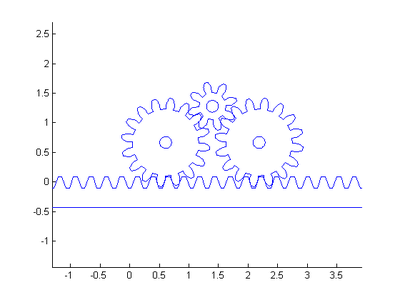
The code simply checks for values of <math>k</math> and <math>\theta_1</math> that satisfy the constraints and then draws the gears and rack for a particular arrangement. There is not always a unique solution, and sometimes no solution for a given set of values. An example of the graphical output is shown below.


