Gen7T
Release status: partially tested
[[image:|center|190px]]
| Description | Generation 7 Electronics with toshiba drivers
|
| License | |
| Author | |
| Contributors | |
| Based-on | [[]]
|
| Categories | |
| CAD Models | |
| External Link | (none)
|
Contents
How to get it
PCBs
Don't get it yet, it's still being tested.
Components
Mouser project nearly completed
Parts Lists
Electronic Components
Miscellaneous
Generation 7 Toshiba Electronics uses a TTL header for serial communications to the host. As many modern PCs lack a serial port, these need an appropriate USB to TTL cable:
| USB to TTL Cable | DigiKey | Mouser | Adafruit Industries | MAKE Store | MakerBot Industries | Watterott |
|---|
An alternative to the USB to TTL cable is the same electronics in form of a small breakout board:
| USB to TTL Breakout Board | Watterott | Sparkfun |
|---|---|---|
| Cable for the above | Watterott |
Another alternative is the E'go USB-TTL adapter, see instructions and limitations below.
Assembly Instructions
coming soon
Setup
Possible Power Sources
Generation 7 Toshiba Electronics should probably only be run from an ATX supply as the power-on sequence needs to be carefully enforced to prevent smoke emission. The 5V power supply can come from any of the standard Gen7 options as below.
Option 1
This is the recommended one. Take your PC power supply and plug in the ATX24, as well as both Disk Power connectors. This will supply the electronics with everything needed.
PC PSUs have two strings with several Disk Power connectors on each string. Each of the strings can supply about 10 Ampéres only, so make sure you plug in only one connector of each string into Gen7's headers.
In this scenario, the ATmega can run and talk to the host with the PSU turned "off" (in Standby mode). So, don't be surprised if you start working with your Mendel and the PSU is still quiet. Each G-code command requiring more juice will turn the PSU on, and some time after the last command off again.
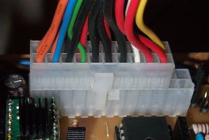
Note: the ATX24 header is backwards compatible to the older ATX20 connector, so if you have a PSU with an ATX20 connector, plug in that. There's only one position where it fits (without pushing very hard) and there is no drawback in using an older supply:
Option 2
This is for people with a non-PC power supply. Make connectors feeding 5 V to the upper Disk Power header, as well as 12 V into both of them. The ATX24 is left empty.
No standby feature here, ATmega, Pololus, motors and heaters are supplied all the time.
Option 3
This allows talking to the ATmega only and may be useful for firmware programming. Leave the ATX24 as well as both Disk Power headers empty. The ATmega will be fed through the serial header. This assumes your serial header actually supplies 5 V actually, some USB-TTL converters need soldering to enable this feature.
As said, this option won't allow to move the motors or to heat the extruder.
Power Source Selection
After choosing an option for the power supply, you have to tell the board where to get 5 V from.
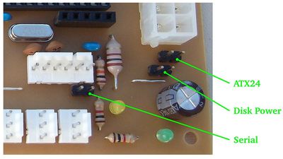
In the lower right corner of the board you see three jumper headers.
- ATX24: recommended for option 1.
- Disk Power: recommended for option 2.
- Serial: required for option 3.
You may jumper one, and only one of them.
NOTE: Actually combinations "ATX24+Serial" and "Disk Power+Serial" are also possible and usefull if you need to drain power from Generation 7 board via serial connector (for example to power max232 based converter board).

