Gen7 Board-AVR 1.5
|
English • العربية • български • català • čeština • Deutsch • Ελληνικά • español • فارسی • français • hrvatski • magyar • italiano • română • 日本語 • 한국어 • lietuvių • Nederlands • norsk • polski • português • русский • Türkçe • українська • 中文(中国大陆) • 中文(台灣) • עברית • azərbaycanca • |
Gen7 Board 1.2 | Gen7 Board 1.1 | Gen7 Board 1.0
Release status: working
| Description | Generation 7 Electronics
|
| License | |
| Author | |
| Contributors | |
| Based-on | [[]]
|
| Categories | |
| CAD Models | |
| External Link | (none)
|
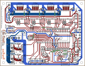
This is the central part of Generation 7 Electronics. A single board with all the features required to run a printer and also including a header to plug in extension boards for future expansion.
Contents
How to get it
All these shops support Gen7 development:
- RepRap DIY ( Traumflug's outlet )
- Paoparts
- eMotion Tech
They have PCBs, components and connector kits available. And thank you to these for supporting Generation 7 Electronics development.
PCBs
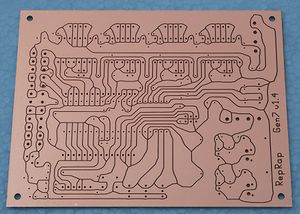
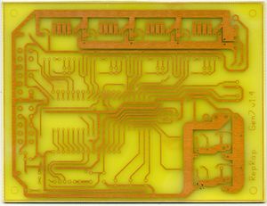
As Gen7 is designed to be manufactured on a RepRap, you can make PCBs yourself, of course. How to do this on a RepRap or a general milling machine is described on the Gen7 main page. Gerbers, PDFs and such are in Gen7's Github repository.
Yet another way is to purchase from one of the many houses specialized in manufacturing prototype PCBs. Gen7 is single sided, so this won't cost a fortune. If you want to sell excess copies, ask Traumflug for a commercial license.
Components
If you want to assemble the collection yourself, see the Parts Lists section.
Parts Lists
To assemble or verify these lists, open the layout with gEDA/PCB and export a "BOM". This will give you a list of all required components.
Special considerations:
- The Pololu Stepper Drivers come with their male headers, so there's no need to purchase them separately.
- Resistors with 0.25 W are on the safe side, even if the footprint name reads "0.125".
- The Pololus can be operated with up to 35 V, so you may want like-rated electrolytic capacitors.
- Pololus require heatsinks, so make sure you get them with the Pololus or get separate ones.
Electronic Components
This list is ordered to match the order of assembly.
| Name | Count | Designations | Vendors | Remarks | |||||
|---|---|---|---|---|---|---|---|---|---|
| MCP2200 I/SO | 1 | U2 | Reichelt | Farnell | RS | Digi-Key | Mouser | This is the USB-TTL adapter | |
| 0.6 mm Wire | 50 cm | Völkner | Digi-Key | Mouser | for the wire bridges on single sided PCBs | ||||
| Resistor 10 Ohms | 2 | R11, R12 | Reichelt | RS | |||||
| Resistor 560 Ohms | 2 | R14, R22 | Reichelt | Völkner | Farnell | RS | Digi-Key | Mouser | |
| Resistor 1 kOhms | 8 | R1, R2, R4, R6, R8, R10, R16, R18 | Reichelt | Völkner | Farnell | RS | Digi-Key | Mouser | |
| Resistor 4.7 kOhms | 2 | RT1, RT2 | Reichelt | Völkner | Farnell | RS | Digi-Key | Mouser | |
| Resistor 10 kOhms | 2 | R3, R30 | Reichelt | Völkner | Farnell | RS | Digi-Key | Mouser | |
| Diode 1N4004 | 2 | D1, D2 | Reichelt | Völkner | Farnell | Digi-Key | Mouser | ||
| Coil 10 uH | 1 | L1 | Reichelt | Farnell | Digi-Key | Mouser | |||
| Crystal 12 MHz | 1 | U7 | Same housing as the one below, the number on the part reads the frequency. | ||||||
| Crystal 16 MHz or 20 MHz | 1 | U6 | Reichelt | Völkner | Farnell | Digi-Key | Mouser | ||
| Reset Switch | 1 | RESET | Reichelt | Völkner | Farnell | RS | Digi-Key | Mouser | |
| Ceramic Capacitor 0.1 uF | 13 | C8, C9, C10, C11, C12, C13, C14, C16, C17, C18, C19, C20, C21 | Reichelt | Völkner | Farnell | RS | Digi-Key | Mouser | |
| LED 3 mm Green | 5 | RxLED, TxLED, LED2, LED5, +5V | Reichelt | Völkner | Farnell | Digi-Key | Mouser | ||
| LED 3 mm Yellow | 1 | Standby | Reichelt | Völkner | Farnell | Digi-key | Mouser | ||
| Ceramic Capacitor 22 pF | 4 | C3, C4, C5, C15 | Reichelt | Völkner | Farnell | RS | Digi-Key | Mouser | |
| Electrolytic Capacitor 10 uF | 2 | CT1, CT2 | Reichelt | Völkner | Farnell | Digi-key | Mouser | ||
| Electrolytic Capacitor 100 uF | 4 | C1, C2, C6, C7 | Reichelt | Völkner | Farnell | Digi-Key | Mouser | ||
| Jumper Header 2 Pin Pairs | 4 pair | J2/J3, J5/J6, J8/J9, J11/J12 | Reichelt | RS | Digi-Key | Mouser | cut them into appropriate pieces | ||
| Jumper Header 2 Pin | 2 | J13, J14 | Reichelt | Völkner | RS | Digi-Key | Mouser | cut them into appropriate pieces | |
| Jumper for the two above | 9 | Reichelt | RS | Digi-Key | Mouser | ||||
| ICSP Header | 1 | CONN6 | Reichelt | RS | Digi-Key | Mouser | alternatively, assemble this out of the remainings of the Jumper 2 Pin Headers | ||
| Pololu Header | 8 or 4 | U2, U3, U4, U5 | Reichelt | Völkner | Digi-Key | Mouser | cut them to appropriate length if needed, you want 8x 8 pins | ||
| Socket for the ATmega | 1 | U1 | Reichelt | Völkner | Farnell | Digi-Key | Mouser | ||
| ATmega 1284P-PU | 1 | Reichelt | RS | Mouser | |||||
| Alternative: ATmega 644-20PU (or 644P-20PU) | 1 | Reichelt | Farnell | Digi-Key | Mouser | ||||
| MOSFET IRLB 8743 | 2 | Q1, Q2 | RS | Mouser | |||||
Connectors
| Name | Count | Designations | Vendors | Remarks | |||||
|---|---|---|---|---|---|---|---|---|---|
| Molex KK100 2 Pin Header | 2 | TEMP_EXT, TEMP_BED | Reichelt | RS | DigiKey | Mouser | |||
| Cable Connector for the above | 2 | Reichelt | RS | DigiKey | Mouser | ||||
| Crimp Contact for the above | 4 | Reichelt | RS | DigiKey | Mouser | ||||
| Molex KK100 3 Pin Header | 3 | X_MIN, Y_MIN, Z_MIN | Reichelt | RS | DigiKey | Mouser | Reichelt are tested to be fully compatible with Molex | ||
| Cable Connector for the above | 3 | Reichelt | RS | DigiKey | Mouser | ||||
| Crimp Contact for the above | 9 | Reichelt | RS | DigiKey | Mouser | same as for TEMP_EXT, TEMP_BED above | |||
| Molex KK100 4 Pin Header | 4 | X_MOT, Y_MOT, Z_MOT, E_MOT | Reichelt | RS | Mouser | ||||
| Cable Connector for the above | 4 | Reichelt | RS | Mouser | |||||
| Crimp Contact for the above | 16 | Reichelt | RS | DigiKey | Mouser | ||||
| USB-B Connector | 1 | CONN1 | Reichelt | ||||||
| Heater Header Molex 26-48-1045 (2 Pin) | 2 | HEATER_EXT, HEATER_BED | RS | DigiKey | Mouser | ||||
| Cable Connector for the above | 2 | RS | DigiKey | Mouser | |||||
| Crimp Contact for the above | 4 | RS | DigiKey | Mouser | |||||
| Alternative to Heater Header: 2 Pin Screw Terminal | 2 | HEATER_EXT, HEATER_BED | Reichelt | DigiKey | Mouser | ||||
| Disk Power Header | 2 | CONN2, CONN3 | Reichelt | RS | DigiKey | Mouser | also see DIY 4 pin molex connector | ||
| ATX24 Power Connector | 1 | CONN1 | RS | DigiKey | Mouser | Molex Mini-Fit 44206-0007. Also known as VAL-U-LOK (20 or 24 Pins). | |||
Miscellaneous
As of v1.5, Generation 7 Electronics has an USB-TTL adapter on board. To connect your Gen7 with a PC, you need just a generic USB device cable.
Last not least, you need four stepper drivers, of course:
| Famous "Pololus" | Pololu stepper driver boards |
|---|---|
| Open Source Alternative | StepStick |
Assembly Instructions
- To find out which components to put where, have the layout on your PC screen available.
- PCBs fabricated with Voronoi paths need more heat, so raise your soldering iron's temperature by about 20 deg Celsius.
- Start with the flattest parts, usually wire bridges or resistors. This way, components won't fall out when you lay the PCB on it's front for soldering. Then continue with parts of raising height, connectors are usually among the last ones.
- The parts lists are sorted with that in mind, simply start at the top and assemble towards the bottom.
- To ease soldering jumper headers and similar components, put a small drop of cyanacrylate glue onto the component side before inserting them. As the PCB is single-sided, this won't hurt the solder point.
- The coil 10 uH looks just like a resistor. It's a bit thicker and comes with rings brown-black-black.
- While soldering a pair of the Pololu headers, insert a Pololu to ensure good alignment.
Caution: Don't solder MOSFETs or insert the ATmega until after the Power Supply Checks.
Assembly in Pictures
Page creation in progress. For now, see Gen7_ExtensionBoard_USB_B_1.0 for the new USB adapter and Gen7 Board 1.4.1 for the remaining.


