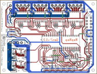
Generation 7 Electronics
Release status: Experimental
| Description | Generation 7 Electronics
|
| License | GPL v2
|
| Author | |
| Contributors | |
| Based-on | [[]]
|
| Categories | |
| CAD Models | |
| External Link |
This is a complete set of electronics loosely based on the (a bit unfortunately named) Gen2OnABoard. It has many features in common with the various Pololu_Electronics variants. So you can as much call it based on RAMPS, as it's a step forward to simplicity and lower price by replacing the Arduino Mega, which is rather a heavyweight for the task at hand, by a simple, cheap, easily solderable (DIP housing) ATmega controller chip.
- Follow development and download files at the Generation_7_Electronics GitHub repository.
- The Forum thread (german) where everything started.
Contents
Design Goals
- PCB easily to manufacture on a RepRap.
- All parts on one board. Except for the Opto Endstops, of course.
- Enough components to run a Mendel or Huxley with extruder and heated bed.
- Easy to set up. For example, this would include an USB port.
- Well available and cheap parts.
- Based on the ATmega644.
Features
- Single board solution.
- Single sided PCB.
- Pololu stepper drivers, exchangeable.
- 4x stepper motor drivers with 1/16 microstepping.
- TODO: on-board USB-RS232 converter.
- Integrated hardware for driving one extruder (stepper, heater and thermistor).
- Integrated hardware for a heated bed (heater, thermistor).
- Integrated hardware for driving a fan.
- Ready to be hooked up on a generic PC power supply unit (PSU).
- Use of standard connectors.
- Debug LEDs for power, Fan and both heater outputs.
- Can turn PSU on and off in software.
- Reset button.
Specifications
- Dimensions about 100 x 120 mm.
- Input voltage through a 20-pin PC PSU.
- Processor: ATmega644 (Atmel Corp.)
More to be defined.
Development
Layout, PCB Editing
Gen7 uses gEDA, a true open source set of Electronics Development Tools (EDA). While gEDA has a bit of a learning curve and has some room for improvement regarding the graphical user interface, it's reliable, fast and well suited for the task. gEDA is available for Linux and Mac OS X and has ready-to-use packages on Debian/Ubuntu and SuSe. To install it on Ubuntu, simply type
sudo apt-get install geda geda-utils
and you'll find schematics and PCB layout editor applications in your applications menu.
Typical Work Loop
RepRap is all about evolution of machines and lowering entry barriers into their (self-)replication, so here you have an easy how-to type description of a typical work loop for changing these electronics with the gEDA/PCB tool chain.
Download the files with Git or GitHubs download button. In the later case choose to download source and unpack that when done.
- Edit changes in the wiring in the schematics (.sch suffix) file. You can open it with the gEDA schematics editor or by double-clicking it.
- When done, save the schematics.
- Open a terminal and change to the directory containing all the files.
- Type:
gsch2pcb <edited schematics>.sch - This created a .net file and updated the PCB layout file.
- Open the file with the .pcb suffix. If you had it open already, keep it open.
- In pcb's menu, select File -> load netlist file.
- Select the file with the .net suffix just created / just renewed.
- In pcb's menu, select connetecs -> optimize rats nest.
- Edit the PCB to match the changes.
- For the next change, go to 2.
Oh yes, putting steps 2 to 9 into a button, like KiCad and Eagle do would be great. gEDA isn't there yet and has other benefits.
PCB Manufacturing
gEDA can export PCBs to the Gerber and other file formats, of course. On how to proceed further with that, see the PCB Milling page.
